1
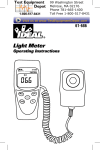
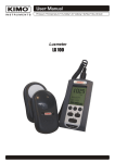
4 light type
LIGHT METER
Model : LX-1108
Your purchase of this LIGHT METER marks a step forward for
you into the field of precision measurement. Although this LIGHT
METER is a complex and delicate instrument, its durable structure
developed. Please read the following instructions carefully and
always keep this manual within easy reach.
OPERATION MANUAL
TABLE OF CONTENTS
1. FEATURES................................................................ 1
2. SPECIFICATIONS......................................................1
2-1 General Specifications......................................... 1
2-2 Electrical Specifications....................................... 4
2-3 Spectrum for Light Sensor......................................... 5
3. FRONT PANEL DESCRIPTION.................................... 6
3-1 Display..............................................................6
3-2 Power Button.................................................... 6
3-3 Hold Button.......................................................6
3-4 REC ( Max/Min ) Button..................................... 6
3-5 Lux/Fc ( Ft-cd ) Button.......................................6
3-6 Range Button.................................................... 6
3-7 Zero Button.......................................................6
3-8 Light Source Button........................................... 6
3-9 Light Sensor Input Socket.................................. 6
3-10 Stand.................................................................... 6
3-11 Battery Compartment/Cover................................... 6
3-12 RS-232 Output..................................................6
3-13 Light Sensor..................................................... 6
3-14 Sensor Cover.................................................... 6
3-15 Light Sensor Plug..............................................6
3-16 LCD display contrast adjust VR.......................... 6
4. MEASURING PROCEDURE......................................... 7
5. AUTO POWER OFF DISABLE......................................10
6. RS232 PC SERIAL INTERFACE................................... 10
7. BATTERY REPLACEMENT.......................................... 11
1. FEATURES
* 5 ranges : 40.00/400.0/4,000/40,000/400,000 Lux, wide
measuring range.
* High resolution : 0.01 Lux to 100 Lux, 0.001 Ft-cd to
10 Ft-cd.
* Selection of lighting type ( Tungsten, Fluorescent,
Sodium or Mercury ).
* Sensor used the exclusive photo diode & color correction
filter, spectrum meet C.I.E. photopic.
* Sensor cosine correction factor meet standard.
* Separate Light Sensor allows user to measure the light at
an optimum position.
* Lux & Foot-candle unit selection.
* Large LCD display with bar graph and indicator.
* Water resistance front panel
* Use the rubber key for the function select.
* Microprocessor circuit ensure high accuracy, and also
and also provides special functions and features.
* LSI circuit provides high reliability and durability.
* Zero adjusting button.
* Data hold, to freeze the desired reading value.
* Peak hold measurement.
* Memory function to display the max. & min. display value
with Recall.
* Auto power auto off or manual power off.
* Compact size and excellent operation.
* Built-in low battery indicator.
* RS-232 computer serial data output.
1
2. SPECIFICATIONS
2-1 General Specifications
Display
Large LCD display.
LCD size 52 x 38 mm, 4 digits.
with bar graph indicator.
Measurement
5 ranges : 40.00 Lux, 400.0 Lux,
& ranges
4,000 Lux, 40,000 Lux, 400,000 Lux.
Unit
Lux, Foot-candle ( Ft-cd ).
Lighting Type
Tungsten lamp, Fluorescent lamp,
Selection
Sodium lamp, Mercury lamp.
Sensor
The exclusive photo diode & color
correction filter, spectrum meet C.I.E.
Cosine correction factor meet standard.
Zero Adjustment External adjustment by pushing button,
( 40.00 Lux range only )
Peak Hold
Data Hold
Memory
Power Off
Over and
Under Range
Indication
Data Output
Operating
Temperature
Operating
Humidity
To hold the peak display.
To freeze the display value.
Save the max. & min. value with Recall.
Auto or manual power off.
Over range indicator : " - - - - "
Under range indicator : " _ _ _ _ "
RS-232 serial data output.
0 蚓 to 50 蚓 ( 32 蚌 to 122 蚌 ).
Less than 80% RH.
2
Power Supply
Power
Consumption
Weight
Dimension
DC 9V battery. 006P, MN1604 ( PP3 )
or equivalent.
Approx. DC 8 mA.
220 g/0.48 LB.
Main instrument :
200 x 68 x 30 mm
( 7.9 x 2.7 x 1.2 inch ).
Light Sensor probe :
Accessories
82 x 55 x 7 mm
( 3.2 x 2.2 x 0.3 inch ).
Instruction Manual...................1 PC.
Light Sensor with protection cover
..............................................1 PC.
3
2-2 Electrical Specifications (23 5 蚓)
Unit
Range
In-range Display
40.00 Lux
Lux
400.0 Lux
4,000 Lux
40,000 Lux
400,000 Lux
4.000 Fc
Foot40.00 Fc
candle
400.0 Fc
( Ft-cd ) 4,000 Fc
40,000 Fc
0 to 40.00 Lux
36.0 to 400.0 Lux
360 to 4,000 Lux
3,600 to 40,000 Lux
10,000 to 400,000 Lux
0 to 3.720 Fc
3.35 to 37.20 Fc
33.5 to 372.0 Fc
335 to 3,720 Fc
930 to 37,200 Fc
Unit
Accuracy
Foot-candle = Ft-cd = Fc
Lux
Footcandle
( Fc )
Range
Resolution
0.01 Lux
0.1 Lux
1 Lux
10 Lux
100 Lux
0.001 Fc
0.01 Fc
0.1 Fc
1 Fc
10 Fc
40.00 Lux
400.0 Lux
( 3% rdg + 0.5 % F.S. )
4,000 Lux
40,000 Lux
400,000 Lux < 100,000 Lux :
( 3% rdg + 0.5 % F.S. )
100,000 Lux :
4.000 Fc
40.00 Fc
400.0 Fc
4,000 Fc
40,000 Fc
@ for reference only
( 3% rdg + 0.5 % F.S. )
< 9,300 Fc :
( 3% rdg + 0.5 % F.S. )
9,300 Fc :
@ for reference only
Note : Accuracy tested by a standard parallel light
tungsten lamp of 2856 袁 temperature.
4
2-3 Spectrum for Light Sensor
5
3. FRONT PANEL DESCRIPTION
3-1
3-2
3-3
3-4
3-5
3-6
3-7
3-8
Display
Power Button
Hold Button
REC ( Max/Min ) Button
Lux/Fc ( Ft-cd ) Button
Range Button
Zero Button
Light Source Button
3-9 Light Sensor Input Socket
3-10 Stand
3-11 Battery Compartment/Cover
3-12 RS-232 Output
3-13 Light Sensor
3-14 Sensor Cover
3-15 Light Sensor Plug
3-16 LCD display contrast adjust VR.
6
4. MEASURING PROCEDURE
1) Push the " Power Button " ( 3-2, Fig. 1 ) to switch the
instrument on.
2) Select the desired measuring unit by pressing the " Lux/Fc
Button " ( 3-5, Fig. 1 ). The display will indicate the
selected unit of " Lux " or " Ft-cd ".
3) Determine the lighting type ( Tungsten, Fluorescent,
Sodium or Mercury lamp) by pressing the " Light
Source Select Button " ( 3-8, Fig. 1 )
Note :
a. For the different lighting type, the LCD will indicate
the following symbols :
Tungsten :
Fluorescent :
Mercury :
Sodium :
b. For the unknown light type, then please select the
" Tungsten Light " type.
4) Select the max. range by using the " Range Button " ( 3-6,
Fig. 1 ).
a. If the main display shows " - - - - ", it indicates
overload condition, select the next higher range.
b. If the main display shows "_ _ _ _ ", it indicates
out-of-range, select the next lower range.
c. As intend to get more accuracy reading, try to select
the range that it have the high resolution
5) Position the " Light Sensor " ( 3-13, Fig. 1 ) directly
under the light source.
7
6) Zero adjustment
a. Cover the " Light Sensor " ( 3-13, Fig, 1 ) using the
" Sensor Cover " ( 3-14, Fig. 1 ).
b. Set to 40.00 Lux range.
c. Pushing the " Zero Button " ( 3-7, Fig. 1 ), LCD will reach
to zero values.
d. Upon completion, remove the sensor cover.
Note :
For precision measurement, only the 40.00 Lux
range need to make Zero Adjustment.
7) Data Hold
a. During the measurement, pushing the " Hold Button "
( 3-3, Fig. 1 ) will hold the measured value & the LCD
will indicate " HOLD " symbol.
b. Push the " Hold Button " again to release the data hold
function.
8) Peak Hold
a. During the measurement, pushing the " Hold Button "
( 3-3, Fig. 1 ) at least 2 to 3 seconds continuously, the
meter will execute the Peak Hold function and at the
same time LCD display will show the " Peak HOLD "
indicator.
b. During execute the Peak Hold function, pushing the
" Hold Button " ( 3-3 , Fig. 1 ) once a while will clear
the Peak Value from the display and enter the new
Peak Value again.
c. When execute the Peak Hold function, pushing the
" Hold Button " ( 3-3 , Fig. 1 ) at least 2 seconds
continuously will cancel the Peak Hold function, the
the " Peak HOLD " indicator will be disappeared.
8
9) Data Record ( Max., Min. reading )
a. The data record function records the maximum and
minimum readings. Press the " REC. Button " ( 3-4,
Fig. 1 ) to start the Data Record function and there
will be a " REC " symbol on the display.
b. With the " REC " symbol on the display :
* Press the " REC Button " ( 3-4, Fig. 1 ) once, the
" REC Max " symbol along with the maximum value
will appear on the display.
Note :
If intend to delete the maximum value, just press
the " Hold Button " ( 3-3, Fig. 1 ) for a while, and
then the display will show the " REC " symbol
only & execute the memory function
continuously.
* Press the " REC. Button " ( 3-4, Fig. 1 ) again, the
" REC Min " symbol along with the minimum value
will appear on the display.
Note :
If intend to delete the minimum value, just press
the " Hold Button " ( 3-3, Fig. 1 ) for a while, and
then the display will show the " REC " symbol
only & execute the memory function
continuously.
c. To exit the memory record function, just press the
" REC " button for 2 seconds at least. The display will
revert to the current reading.
9
5. AUTO POWER OFF DISABLE
The instrument has " Auto Power Off " function in order to
prolong battery life. The meter will shut off automatically if
none of the buttons are pressed in approx. 10 min.
To disable this function, Select the memory record function
during the measurement by pressing the " REC. Button "
3-4, Fig. 1 ).
6. RS232 PC SERIAL INTERFACE
The instrument has RS232 PC serial interface via a 3.5 mm
terminal ( 3-12, Fig. 1 ).
The data output is a 16 digit stream which can be utilized
for user's specific application.
A RS232 lead with the following connection will be required
to link the instrument with the PC serial port.
Meter
PC
(9W 'D" Connector)
(3.5 mm jack plug)
Center Pin.............................Pin 4 Pin 2
Ground/shield..............................Pin 2 Pin 5
2.2 K
resistor
The 16 digits data stream will be displayed in the
following format :
D15 D14 D13 D12 D11 D10 D9 D8 D7 D6 D5 D4 D3 D2 D1 D0
10
Each digit indicates the following status :
D0
D1 & D8
End Word
Display reading, D1 = LSD, D8 = MSD
For example :
If the display reading is 1234, then D8 to D1 is :
00001234
D9
D10
D11 & D12
D13
D14
D15
Decimal Point(DP), position from right to the left
0 = No DP, 1= 1 DP, 2 = 2 DP, 3 = 3 DP
Polarity
0 = Positive
1 = Negative
Annunciator for Display
Lux = 15
Ft-cd = 16
When send the upper display data = 1
When send the lower display data = 2
4
Start Word
RS232 FORMAT : 9600, N, 8, 1
7. BATTERY REPLACEMENT
1) When the left corner of LCD display show "
",
is necessary to replace the battery. However, in-spec.
measurement may still be made for several hours after
low battery indicator appears.
2) Slide the " Battery Cover " ( 3-11, Fig. 1 ) away from the
instrument and remove the battery.
3) Replace with 9V battery ( Alkaline or Heavy duty type )
and reinstate the cover.
4) Make sure the battery cover is secured after changing the
battery.
11
0211-LX-1108