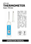
1
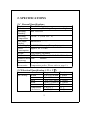
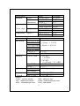
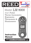
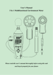
Anemometer, Hygrometer
Light Meter, Thermometer
TABLE OF CONTENTS
1. FEATURES.........................................................................
1
2. SPECIFICATIONS.............................................................. 2
3. FRONT PANEL DESCRIPTION....................................... 4
3-1 Power Button................................................................. 4
3-2 Hold Button................................................................... 4
3-3 Max. / Min. Button........................................................... 4
3-4 Unit / Zero Button.......................................................... 4
3-5 ℃/℉, Lux/Ft-cd button.................................................. 4
3-6 Function Button............................................................. 4
3-7 Air Flow Sensor............................................................. 4
3-8 Thermocouple Input Socket........................................... 4
3-9 R.H. Sensor.................................................................... 4
3-10 Light Sensor................................................................. 4
3-11 LCD display................................................................. 4
3-12 Battery Compartment / Cover...................................... 4
3-13 Wristlet......................................................................... 4
4. MEASURING PROCEDURES...........................................
4-1 AIR VELOCITY EASUREMENT................................
4-2 TEMPERATURE MEASUREMENT
(Thermocouple)...............................................................
4-3 RELATIVE HUMIDITY MEASUREMENT...............
4-4 LIGHT MEASUREMENT............................................
5
5
5
6
6
5. OTHER FUNCTIONS.......................................................... 7
6. BATTERY REPLACEMENT.............................................. 8
7. OPTIONAL THERMOCOUPLE PROBE AND
OTHER ACCESSORIES.................................................... 9
1. FEATURES
* 4 in 1 professional measuring instrument: Anemometer,
Hygrometer, Thermometer, and Light meter.
* Tiny bone shape with lightweight and small size case design
are suitable for handling with one hand.
* Wristlet design provides extra protection to the instrument
especially for user one hand operation.
* Low-friction ball bearing mounted wheel design provides
high accuracy at high and low air velocity.
* Exclusive photo diode and color correction filter light sensor,
spectrum meets C.I.E. photopic.
* High precision thin-film capacitance humidity sensor with
fast response to the humidity changes.
* Standard type K (NiCr-NiAl) thermocouple input jack
suitable for all kinds of type K probe.
* Built- in microprocessor circuit assures excellent
performance and accuracy.
* Concise and compact buttons arrangement, easy operation.
* Memorize the maximum and minimum value with recall.
* ℃/℉ selectable by pressing button on the front panel.
* Lux/Feet-candle selectable by pressing button on the front
panel.
* Air velocity measuring units selectable by pressing button on
the front panel for five kinds of units.
* Multi channel display for relative humidity and temperature
measured values or air velocity and temperature measured
values at the same time.
* Zero button design makes light meter calibration.
* Hold function to freeze the current reading value.
1
2. SPECIFICATIONS
2-1 General Specifications
Display
8 mm LCD display
Measurement Anemometer, Humidity, Temperature. Light
Operating
Max. 80% RH.
Humidity
Operating
0 to 50° C (32 to 122° F)
Temperature
Over Input
Indication of "- - - - "
Display
Power Supply 006P DC 9V battery (Heavy duty type)
Power
Approx. DC 6.2 mA
Consumption
Weight
160g (battery included)
Dimension
HWD 156x60x33 mm (6.14x2.36x1.29 inch).
Standard Instruction
Manual
Accessory
Optional
Carrying case.
Accessories Temperature probe ( Please refer to page 9 ).
2-2 Electrical Specification ( 23 ± 5℃ )
Measurement
Air velocity
ft/min
m/s
km/h
MPH
knots
Temperature
( thermister)
Range
80 to 5910 ft/min
0.4 to 30.0 m/s
1.4 to 108.0 km/h
0.9 to 67.0 mile/h
0.8 to 58.3 knots
32 to 122 ℉
0 to 50 ℃
2
Resolution
1 ft/min
0.1 m/s
0.1 km/h
0.1 MPH
0.1 knots
0.1 ℉
0.1 ℃
Measurement
Humidity
% RH
Temperature
( thermister)
Light
Lux
* auto range Ft-cd
Temperature ( Type K )
Range
10 to 95 %RH
32 to 122 ℉
0 to 50 ℃
0 to 2,200 Lux
Resolution
0.1 %RH
0.1 ℉
0.1 ℃
1 Lux
1,800 to 20,000 Lux 10 Lux
0 to 204.0 Fc
0.1 Ft-cd
170 to 2,000 Fc 1 Ft-cd
-148 to 2372 ℉ 0.1 ℉
-100 to 1300 ℃ 0.1 ℃
Measurement Range
Accureacy
Air velocity 80 to 5910 ft/min
0.4 to 30.0 m/s
≦ 20 m/s : ± 3% F.S.
1.4 to 108.0 km/h > 20 m/s : ± 4% F.S.
0.9 to 67.0 mile/h
0.8 to 58.3 knots
32 to 122 ℉
± 2.5 ℉
0 to 50 ℃
± 1.2 ℃
Humidity
10 to 95 %RH < 70% RH :
± 4 %RH
≧70% RH :
: ± ( 4%rdg + 1.2 %RH )
32 to 122 ℉
± 2.5 ℉
0 to 50 ℃
± 1.2 ℃
Light
0 to 20,000 Lux ± 5% rdg ± 8 dgt
0 to 2,000 Fc
Temperature -148 to 2372 ℉ ± (1% rdg + 2℉)
( Type K ) -100 to 1300 ℃ ± (1% rdg + 1℃)
Remark :
ft/min : feet per minute
m/s : meters per second
km/h : kilometers per hour
MPH : miles per hour
knots : nautical miles per hour
Ft-cd : feet candle
3
3. FRONT PANEL DESCRIPTION
Fig. 1
3-1 Power Button
3-2 Hold Button
3-3 Max. / Min. Button
3-4 Unit / Zero Button
3-5 /℃ ℉ Button
Lux/Ft-cd Button
3-6 Function Button
3-7 Air Flow Sensor
3-8 Thermocouple Input Socket
3-9 R.H. Sensor
3-10 Light Sensor
3-11 LCD display
3-12 Battery Compartment / Cover
3-13 Wristlet
4
4. MEASURING PROCEDURE
4-1 Air Velocity Measurement
1) Power on the instrument by pressing the " Power Button "
( 3-1, Fig. 1 ).
2) Select the Anemometer function by pressing " Function
Button " ( 3-6, Fig. 1 ).
3) Press the " Unit/Zero Button " ( 3-4, Fig. 1 ) to select
unit that you want and then face the " Air Flow Sensor "
( 3-7, Fig. 1 ) to the source of wind.
4) Allow time for the reading to become stable and note the
value indicated. From a practical point of view the velocity
may fluctuate.
4-2 Temperature Measurement ( Thermocouple )
1) Power on the instrument by pressing the " Power Button "
( 3-1, Fig. 1 )..
2) Plug a type K thermocouple probe in the " Thermocouple
Input Socket " ( 3-8, Fig. 1 ).
3) Select the Temperature function by pressing " Function
Button " ( 3-6, Fig. 1 )
4) Contact the Thermocouple Sensor Head with measuring
object and the reading value will be displayed on the LCD
display.
Measuring Consideration of Temperature
Measurement ( Thermocouple )
* Please make sure the polarity is correct when you plug a
thermocouple probe in the Temp. input socket.
5
* The temperature difference between thermocouple
probe and thermometer will cause an inaccurate
measuring result. Therefore, for the best measuring
and accuracy performance, whenever change a probe or
plug a new probe, thermal equivalent between probe
plug and meter's input socket is a necessary condition.
Thermal equivalent procedure may take few minutes
and apply only when the probe has been exposed to an
ambient temperature different from the meter.
4-3 Humidity & Ambient Temperature Measurement
1) Power on the instrument by pressing the " Power
Button " (3-1, Fig. 1).
2) Select the Relative Humidity function by pressing
"Function Button " ( 3-6, Fig. 1 ).
3) At the mean time the reading value of relative humidity
and temperature will be displayed on the LCD display.
4) When the meter is applied in a new environment, a few
minutes are required to reach a stable condition.
4-4 Light Measurement
1) Power on the instrument by pressing the " Power Button "
( 3-1, Fig. 1 ).
2) Select the Light Measurement function by pressing the
" Function Button " ( 3-6, Fig. 1 ) until the light value is
displayed. The light display digits are oriented 180° from
the other function displays for easy exposure and output
reading of the light sensor.
3) Press the " Lux/Ft-cd Button " ( 3-5, Fig. 1 ) to
select measuring unit " Lux " or " Ft-cd ".
6
Zero Offset Adjustment of Light Function :
* For best results zero the light sensor prior to use in a
dark environment. Placing the light sensor end of the
meter under a desktop or flat surface so as to block
any light can accomplish this. Then press the
"Unit/Zero Button" ( 3-4, fig. 1 ) to set the meter
indication to zero.
* Zero point can drift due to environment temperature
and battery power change as well as for other reasons.
It is recommended that the zero be checked
frequently using the above procedure.
5. OTHER FUNCTIONS
5-1 Hold Function
Whenever press the "Hold Button (3-2, Fig. 1)" will freeze
the current reading value with a "HOLD" symbol on the
display.
5-2 Data Record Function
1) The Data Record function records & displays the maximum
and minimum reading values. Start the Data Record function
by pressing the " Max./Min. Button " ( 3-3, Fig. 1 ) once.
There will be a " REC " symbol on the display.
7
2) With the REC symbol on the display :
(a) Press the " Max./Min. Button " ( 3-3, Fig. 1 ) once and the
" Max " symbol along with the maximum value will appear on
the display.
(b) Press the " Max./Min. Button " again, the " Min " symbol
along with the minimum value will appear on the display.
(c) To exit the memory record function, press the " Max./Min.
Button " continuously for at least 2 seconds. The display will
revert to the current reading.
(d) Clear the Max./Min. value recorded by pressing the
" Hold Button " ( 3-2, Fig. 1 ) once. Previous recorded
Max./Min. value will be given up and then revert to the
REC. function keep on recording.
5-3 Auto Power Off Disable
In order to prolong the battery life, the instrument has "Auto
Power Off " function. The meter will switch off automatically if
no buttons are pressed for around 10 minutes.
6. BATTERY REPLACEMENT
1) When the LCD display shows "
" symbol, it is necessary
to replace the battery. However measurement may still be
made for several hours after the low battery indicator appears.
2) Open the " Battery Compartment / Cover " ( 3-12, Fig. 1) and
remove the battery.
3) Install a 9V battery (Alkaline or Heavy duty type) and then
reinstate the cover.
8
7. OPTIONAL TEMPERATURE PROBE
AND OTHER ACCESSORIES
Thermocouple Probe
(Type K) TP-01
* Measuring Range : -40 to 250 ℃
( -40 to 482 ℉ )
* Max. short-term operating temperature:
* It's an ultra fast response naked-bead
thermocouple suitable for many general
Thermocouple Probe
(Type K) TP-02A
purpose application.
* Measuring Range : -50 to 900 ℃
( -50 to 1650 ℉ )
Thermocouple Probe * Dimension: 10cm tube, 3.2 mm Dia.
(Type K) TP-03
* Measuring Range : -50 to 1200 ℃
( -50 to 2200 ℉ )
Thermocouple Probe * Dimension: 10cm tube, 8 mm Dia.
(Type K) TP-04
* Measuring Range : -50 to 400 ℃
* surface Temp.
( -50 to 752 ℉ )
probe.
* Size :
Temp. sensing head - 15 mm Dia.
Carrying case
CA-52A
Probe length - 12 mm.
* High quality carrying case with sash.
9
0306-DLAF8000