1
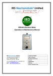
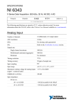
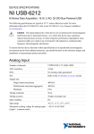
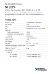
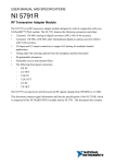
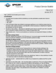
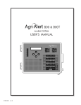
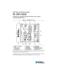
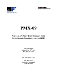
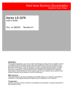
USER MANUAL
NI PXImc Devices
NI PXIe-8830mc PXImc Processor Module
This document provides reference information for PXI Express and the NI PXIe-8830mc
PXImc processor module.
Contents
Electromagnetic Compatibility Guidelines............................................................................... 1
Related Documentation.............................................................................................................2
PXI Express Features................................................................................................................ 2
Benefits of PXI Express.................................................................................................... 2
NI PXIe-8830mc Overview...................................................................................................... 3
Functional Overview.........................................................................................................3
Functional Description...................................................................................................... 4
National Instruments Software..........................................................................................5
Configuration............................................................................................................................ 7
System CMOS...................................................................................................................7
Upgrading System Memory.............................................................................................. 8
Specifications............................................................................................................................ 9
Physical........................................................................................................................... 10
Power Requirements....................................................................................................... 11
Environment.................................................................................................................... 11
Cleaning.......................................................................................................................... 12
Safety.............................................................................................................................. 12
Appendix A: Front Panel Connector Pinouts..........................................................................13
Ethernet........................................................................................................................... 13
Universal Serial Bus........................................................................................................15
Worldwide Support and Services............................................................................................ 16
Electromagnetic Compatibility Guidelines
This product was tested and complies with the regulatory requirements and limits for
electromagnetic compatibility (EMC) stated in the product specifications. These requirements
and limits provide reasonable protection against harmful interference when the product is
operated in the intended operational electromagnetic environment.
This product is intended for use in industrial locations. However, harmful interference may
occur in some installations, when the product is connected to a peripheral device or test object,
or if the product is used in residential or commercial areas. To minimize interference with
radio and television reception and prevent unacceptable performance degradation, install and
use this product in strict accordance with the instructions in the product documentation.
Furthermore, any modifications to the product not expressly approved by National Instruments
could void your authority to operate it under your local regulatory rules.
Caution To ensure the specified EMC performance, operate this product only with
shielded cables and accessories.
Caution To ensure the specified EMC performance, USB cables must be no longer
than 30 m (100 ft). Ethernet cable can be longer than 30 m (100 ft).
Related Documentation
The following documents contain information that you might find helpful as you read this
manual:
•
Your chassis documentation
•
NI-PXImcTM Help file included with NI-PXImc driver
•
PXI Express Hardware Specification, Revision 2.0
•
PXI-6 PXI Express Software Specification
•
PICMG CompactPCI Express EXP.0 R1.0 Specification
•
PCI Express Base Specification, Revision 2.1, PCI Special Interest Group
•
PXI MultiComputing Hardware Specification, Revision 1.0
•
PXI MultiComputing Software Specification, Revision 1.0
PXI Express Features
Benefits of PXI Express
The PXI (PCI eXtensions for Instrumentation) industry standard, an open specification
governed by the PXI Systems Alliance (PXISA), has quickly gained adoption and grown in
prevalence in test, measurement, and control systems since its release in 1998. One of the key
elements driving the rapid adoption of PXI is its use of PCI in the communication backplane.
As the commercial PC industry has improved the available bus bandwidth by evolving PCI to
PCI Express, PXI is now able to meet even more application needs by integrating PCI Express
into the PXI standard. By taking advantage of PCI Express technology in the backplane, PXI
Express increases the available PXI bandwidth from up to 132 MB/s to up to 8 GB/s for a
more than 60x improvement in bandwidth.
PXI Express maximizes both hardware and software compatibility with PXI modules. PXI
Express hybrid slots deliver both PCI and PCI Express signaling to accept devices that use
PXI communication and triggering or the newer PXI Express standard. Software compatibility
is maintained because PCI Express uses the same OS and driver model as PCI, resulting in
complete software compatibility among PCI-based systems, for example PXI, and PCI
Express-based systems such as PXI Express.
2 | ni.com
|
NI PXImc Devices User Manual
PXI Express, like PXI, leverages from the CompactPCI specification to define a rugged,
modular form factor that offers superior mechanical integrity and easy installation and removal
of hardware components. PXI Express products offer higher and more carefully defined levels
of environmental performance required by the shock, vibration, temperature, and humidity
extremes of industrial environments. Mandatory environmental testing and active cooling is
added to the CompactPCI mechanical specification to ease system integration and ensure
multivendor interoperability.
The demanding timing and synchronization requirements of instrumentation systems are met
by the integrated features of PXI Express. Not only are the trigger bus, 10 MHz system
reference clock, and star trigger bus available in PXI retained by PXI Express, but new timing
and synchronization features that include a 100 MHz differential system reference clock for
the synchronization of multiple modules and three differential star trigger buses for the
distribution of precise clock and trigger signals have been added. Differential timing and
synchronization signals provide PXI Express systems with increased noise immunity and the
ability to transmit clock signals at higher frequencies.
NI PXIe-8830mc Overview
Functional Overview
The NI PXIe-8830mc is a PXImc device1 module that allows the attachment of subsystems
such as standalone instruments, PCs, or other PXI Express systems to an existing PXI Express
system via a high-bandwidth, low-latency PXI Express backplane Gen2 x8 link. The NI
PXIe-8830mc contains a PXImc logic block that makes it possible to join systems together
nontransparently.
The following figure illustrates where the PXImc logic block is applied to join the root
complexes of two systems.
1
Refer to the PXI-7 PXI MultiComputing Hardware Specification Revision 1.0, available on the
pxisa.org website, for relevant terminology and concepts used in this guide.
NI PXImc Devices User Manual |
© National Instruments
|
3
Figure 1. PXImc System Diagram
PXImcDevice
PrimarySystemHost
CPU
MC
Memory
Memory
CPU
Root Complex
Root Complex
Endpoint
Endpoint
Endpoint
Endpoint
Bridge
NTB
Endpoint
Endpoint
PXImc Logic Block
Physical
Expansion
Slot/Port
Endpoint
Endpoint
In this example, the system on the right is designated as a PXImc device because it contains
the PXImc logic block (that is, the NI PXIe-8830mc). The system on the left is designated the
primary system host, which serves as the central connection hub for all other PXImc devices.
Refer to the NI-PXImc Help and readme.html files included with the NI-PXImc driver for
feature updates.
Functional Description
The NI PXIe-8830mc is a modular PC in a PXI Express 3U-size form factor. The following
figure is a functional block diagram of the NI PXIe-8830mc. Following the diagram is a
description of each logic block shown.
4 |
ni.com |
NI PXImc Devices User Manual
Figure 2. NI PXIe-8830mc Block Diagram
1x8
PCI Express
Switch
x8
Processor
Intel Core
i7
Memory Bus Ch. A
SO-DIMM
DDR3L SDRAM
PC3 12800
x4 DMI2
PXI
Express
USB 2.0 x2
RJ45
Port
Intel I217-LM
Gigabit
PHY
Intel
8 Series
PCH
SATA
USB 2.0 x2
SATA Solid
State Drive
SPI
LPC
FLASH
Watchdog
Trigger
PXI
Triggers
The NI PXIe-8830mc consists of the following logic blocks on one circuit card assembly
(CCA):
•
The processor is an Intel® Core™ i7 4700EQ processor (6 MB Cache, 2.3 GHz). The
processor connects to the SO-DIMM block through the DDR3L interface supporting up
to 1600 MHz SO-DIMMs, the PCH through a x4 DMI2 (Direct Media Interface)
interface supporting up to 5 GT/s per lane.
•
The SO-DIMM block consists of one 64-bit DDR3L SDRAM socket that can hold up to
8 GB of memory.
•
The Platform Controller Hub (PCH) provides the USB, PCI Express x1, and LPC
interfaces that connect to the peripherals on the NI PXIe-8830mc.
•
The USB block consists of two Hi-Speed USB 2.0 connectors.
•
The Ethernet Port block consists of an Intel® I217-LM Gigabit Ethernet Connection.
•
The Watchdog block consists of a watchdog timer that can reset the processor module or
generate triggers.
•
The PXI Express Connectors connect the NI PXIe-8830mc to the PXI Express/
CompactPCI Express backplane.
National Instruments Software
National Instruments has developed several software tools you can use with the
NI PXIe-8830mc.
National Instruments’ hardware and software work together to help you make the most of your
PXI Express system. The LabVIEW, Measurement Studio, and LabWindows™/CVI™
NI PXImc Devices User Manual |
© National Instruments
|
5
application development environments combine with leading hardware drivers such as NIDAQmx to provide exceptional control of NI hardware. Instrument drivers are available at
ni.com/idnet to simplify communication with instruments over a variety of buses.
LabVIEW is a powerful and easy-to-use graphical programming environment you can use to
acquire data from thousands of different instruments including USB, IEEE 488.2, VXI, serial,
PLCs, and plug-in boards. LabVIEW helps you convert acquired data into meaningful results
using powerful data analysis routines. Add-on tools provide additional specialized
functionality. For more information, visit ni.com/labview and ni.com/toolkits.
If you prefer to use Microsoft’s Visual Basic, Visual C++, and Visual Studio .NET for the core
of your application, Measurement Studio adds tools for measurement and automation to each
language. For more information, visit ni.com/mstudio.
LabWindows/CVI is an interactive ANSI C programming environment designed for building
virtual instrument applications. LabWindows/CVI delivers a drag-and-drop editor for building
user interfaces, a complete ANSI C environment for building your test program logic, and a
collection of automated code generation tools, as well as utilities for building automated test
systems, monitoring applications, or laboratory experiments. For more information, visit
ni.com/lwcvi.
NI-DAQmx provides an extensive library of functions you can call from your application
development environment or interactive environment such as NI Signal Express. These
functions provide an intuitive API for National Instruments multifunction DAQ products.
Features available include analog input (A/D conversion), buffered data acquisition (highspeed A/D conversion), analog output (D/A conversion), waveform generation, digital I/O,
counter/timer operations, SCXI signal conditioning, RTSI or PXI Express synchronization,
self-calibration, messaging, and acquiring data to extended memory. For more information,
visit ni.com/daq.
National Instruments modular instruments use specialized drivers suited to each product’s
specialization. Express VIs provide customized, interactive programming of instruments in a
single interface and soft front panels provide an interface for testing the functionality of each
instrument with no programming required. NI Switches, DMMs, High-Speed DIO, HighSpeed Digitizers, and Sources each have customized drivers for high-end modular
instrumentation systems. RF applications leverage two drivers, NI-RFSG and NI-RFSA and
Dynamic Signal Acquisition is available through NI-DAQmx. For more information, visit
ni.com/modularinstruments.
You can expand the timing and triggering functionality of your PXI Express system with PXI
Express Timing and Synchronization products. These products provide precision clock
sources, custom routing of triggers for multichassis synchronization, clock sharing, and more
and are programmed with NI-Sync. For more information, visit ni.com/pxi.
NI-VISA is the National Instruments implementation of the VISA specification. VISA is a
uniform API for communicating and controlling USB, Serial, GPIB, PXI, PXI Express, VXI,
6 |
ni.com |
NI PXImc Devices User Manual
and various other types of instruments. This API aids in the creation of portable applications
and instrument drivers. For information about writing your own PXI Express instrument driver
with NI-VISA, refer to the NI-VISA Getting Started Manual and the readme.txt file in the
NI-VISA directory. For more information, visit ni.com/visa.
With LabVIEW for Linux and support for more than two hundred devices on Linux with the
NI-DAQmx driver, you now can create Virtual Instruments based on the Linux OS. The NIVISA driver for Linux has improved instrument control in Linux, and NI Modular Instruments
are partially supported. For more information, visit ni.com/linux.
Configuration
System CMOS
The NI PXIe-8830mc contains memory backed up by a battery to store BIOS configuration
information.
Complete the following steps to clear the CMOS contents:
1. Power off the chassis.
2. Remove the processor module from the chassis.
3. Press the push-button switch, as shown in the following figure.
4. Wait 10 seconds.
5. Reinstall the processor module in the chassis.
NI PXImc Devices User Manual |
© National Instruments
|
7
Figure 3. Clearing the CMOS Contents
1
1. Push-Button Switch SW1
Upgrading System Memory
You can change the amount of installed RAM on the NI PXIe-8830mc by upgrading the
DDR3 SO-DIMMs. Complete the following steps to upgrade the RAM.
1. Remove the NI PXIe-8830mc from the PXI Express chassis.
2.
Locate the DDR3 SO-DIMM module on the side of the processor module, as shown in
the figure.
3.
Remove the installed DDR3 SO-DIMM module, if necessary.
4.
Install the new DDR3 SO-DIMM module into the slot.
NI PXIe-8830mc System Memory Information
National Instruments offers the following types of SO-DIMMs for use with the
NI PXIe-8830mc processor module.
Note National Instruments has tested and verified that the DDR3 SO-DIMMs we
sell work with the NI PXIe-8830mc processor module. We recommend you purchase
8 |
ni.com |
NI PXImc Devices User Manual
•
•
your DDR3 SO-DIMM modules from National Instruments. Other off-the-shelf
DDR3 SO-DIMM modules are not guaranteed to work properly.
PC3-12800 (DDR3 1600) 4 GB, 256 MB × 64, CL 9, 1.18 in. max (NI part number
782341-4096)
PC3-12800 (DDR3 1600) 8 GB, 512 MB × 64, CL 9, 1.18 in. max (NI part number
782341-8192)
Figure 4. Installing a DDR3 SO-DIMM in an NI PXIe-8830mc Processor Module
1
2
1. DDR3 SO-DIMM Module
2. DDR3 SO-DIMM Socket
Specifications
This section lists the system specifications for the following product only:
•
NI PXIe-8830mc (156252x-011L)
Note The NI assembly number in parentheses follows the model number. Ensure
that the specifications of interest match the NI assembly number on either the front
or back side of the board.
Note x denotes all assembly letter revisions.
Note These specifications are typical at 25 °C, unless otherwise stated, and are
subject to change without notice.
NI PXImc Devices User Manual
|
© National Instruments
|
9
Physical
............................................................................
Board dimensions
2-Slot 3U PXI Express
Slot requirements
............................................................................
Two peripheral slot (PXI Express)
Weight
............................................................................
0.82 kg (1.80 lb) typical
5.067 in. [128.70 mm]
NATIONAL
INSTRUMENTS
NI PXIe-8830mc
PXImc Processor Module
3.750 in. [95.24 mm]
1.572 in. [39.93 mm]
1.064 in. [27.02 mm]
0.000 in. [0.00 mm]
10 |
ni.com
|
NI PXImc Devices User Manual
0.585 in. [14.86 mm]
0.661 in. [16.79 mm]
0.000 in. [0.00 mm]
1.588 in. [40.34 mm]
0.372 in. [9.45 mm]
0.707 in. [17.96 mm]
Figure 5. NI PXIe-8830mc Front Panel Dimensions
Power Requirements
Power Rail
Typical Current
Maximum Current
+3.3 V
1450 mA
2180 mA
+12 V
3750 mA
3940 mA
+5 VAux
70 mA
110 mA
Note: Does not include any attached USB devices.
Environment
Maximum
............................................................................
altitude
2,000 m (800 mbar)
Pollution Degree
............................................................................
2
Indoor use only.
Operating Environment
............................................................................
Ambient temperature range
0 to 40 °C
(maximum performance)
Ambient temperature range
............................................................................
0 to 55 °C (Tested in accordance with
IEC-60068-2-1 and IEC-60068-2-2. Meets
MIL-PRF-28800F Class 3 low temperature
limit and MIL-PRF-28800F Class 2 high
temperature limit.)
Relative
............................................................................
humidity range
10 to 90%, noncondensing (Tested in
accordance with IEC-60068-2-56.)
Storage Environment
Ambient
............................................................................
temperature range
-40 to 71 °C (Tested in accordance with
IEC-60068-2-1 and IEC-60068-2-2. Meets
MIL-PRF-28800F Class 3 limits.)
Relative
............................................................................
humidity range
5 to 95%, noncondensing (Tested in
accordance with IEC-60068-2-56.)
Shock and Vibration
Operational
............................................................................
shock
30 g peak, half-sine, 11 ms pulse (Tested in
accordance with IEC-60068-2-27. Meets MILPRF-28800F Class 2 limits.)
NI PXImc Devices User Manual |
© National Instruments
|
11
Random Vibration
Operating
............................................................................5 to 500 Hz, 0.3 grms
Nonoperating
............................................................................
5 to 500 Hz, 2.4 grms (Tested in accordance
with IEC-60068-2-64. Nonoperating test
profile exceeds the requirements of MILPRF-28800F, Class 3.)
Cleaning
Use a dry, low-velocity stream of air to clean the NI PXIe-8830mc processor module. If
needed, use a soft, nonmetallic brush for cleaning around components.
Make sure that the device is completely dry and free from contaminants before returning it to
service.
Safety
This product is designed to meet the requirements of the following electrical equipment safety
standards for measurement, control, and laboratory use:
•
IEC 61010-1, EN 61010-1
•
UL 61010-1, CSA 61010-1
Note For UL and other safety certifications, refer to the product label or the Online
Product Certification section.
Electromagnetic Compatibility
This product meets the requirements of the following EMC standards for electrical equipment
for measurement, control, and laboratory use:
•
EN 61326-1 (IEC 61326-1): Class A emissions; Basic immunity
•
EN 55011 (CISPR 11): Group 1, Class A emissions
•
AS/NZS CISPR 11: Group 1, Class A emissions
•
FCC 47 CFR Part 15B: Class A emissions
•
ICES-001: Class A emissions
Note In the United States (per FCC 47 CFR), Class A equipment is intended for
use in commercial, light-industrial, and heavy-industrial locations. In Europe,
Canada, Australia and New Zealand (per CISPR 11) Class A equipment is intended
for use only in heavy-industrial locations.
Note Group 1 equipment (per CISPR 11) is any industrial, scientific, or medical
equipment that does not intentionally generates radio frequency energy for the
treatment of material or inspection/analysis purposes.
Note For EMC declarations and certifications, and additional information, refer to
the Online Product Certification section.
12 |
ni.com
|
NI PXImc Devices User Manual
CE Compliance
This product meets the essential requirements of applicable European Directives, as follows:
•
2006/95/EC; Low-Voltage Directive (safety)
•
2004/108/EC; Electromagnetic Compatibility Directive (EMC)
Online Product Certification
To obtain product certifications and the DoC for this product, visit ni.com/certification, search
by model number or product line, and click the appropriate link in the Certification column.
Environmental Management
NI is committed to designing and manufacturing products in an environmentally responsible
manner. NI recognizes that eliminating certain hazardous substances from our products is
beneficial to the environment and to NI customers.
For additional environmental information, refer to the Minimize Our Environmental Impact
web page at ni.com/environment. This page contains the environmental regulations and
directives with which NI complies, as well as other environmental information not included in
this document.
Waste Electrical and Electronic Equipment (WEEE)
EU Customers At the end of the product life cycle, all NI products must be
disposed of according to local laws and regulations. For more information about
how to recycle NI products in your region, visit ni.com/environment/weee.
电子信息产品污染控制管理办法(中国 RoHS)
中国客户 National Instruments 符合中国电子信息产品中限制使用某些有害物
质指令(RoHS)。关于 National Instruments 中国 RoHS 合规性信息,请登录
ni.com/environment/rohs_china。(For information about China RoHS
compliance, go to ni.com/environment/rohs_china.)
Appendix A: Front Panel Connector Pinouts
Ethernet
The following figure shows the location and pinouts for the Ethernet connector on the
NI PXIe-8830mc. The following table lists and describes the Ethernet connector signals.
AMP manufactures a mating connector, part number 554739-1.
NI PXImc Devices User Manual |
© National Instruments
|
13
Figure 6. Ethernet Connector Location and Pinout
NATIONAL
INSTRUMENTS
NI PXIe-8830mc
PXImc Processor Module
1
Ethernet
8
Table 1. Ethernet Connector Signals
Pin
Fast Ethernet
Gigabit Ethernet
1
TX+
TX_A+
2
TX-
TX_A-
3
RX+
RX_B+
4
NC
TX_C+
5
NC
TX_C-
6
RX-
RX_B-
7
NC
RX_D+
8
NC
RX_D-
Note The Ethernet processor module can perform an automatic crossover, thus
eliminating the need for crossover cables.
Table 2. 10/100/1000 LAN Connector LED States
LED
Color
ACT/LINK
Green
Off
LAN link is not established.
ACT/LINK
Green
On (steady state)
LAN link is established.
14 |
ni.com
|
LED State
NI PXImc Devices User Manual
Condition
Table 2. 10/100/1000 LAN Connector LED States (Continued)
LED
Color
LED State
ACT/LINK
Green
On (brighter and
pulsing)
Condition
The processor module is communicating with
another computer on the LAN.
10/100/1000 (None) Off
10 Mbit/sec data rate is selected.
10/100/1000 Green
100 Mbit/sec data rate is selected.
On
10/100/1000 Amber On
1000 Mbit/sec data rate is selected.
Universal Serial Bus
The following figure shows the location and pinouts for the Universal Serial Bus (USB)
connector on the NI PXIe-8830mc. Each processor module has two USB ports on the front
panel. The following table lists and describes the USB connector signals.
Figure 7. USB Connector Location and Pinout
NATIONAL
INSTRUMENTS
NI PXIe-8830mc
PXImc Processor Module
4
1
USB 2.0
Table 3. USB 2.0 Connector Signals
Pin
Signal Name
Signal Description
1
VCC
Cable Power (+5 V)
2
-Data
USB Data -
NI PXImc Devices User Manual |
© National Instruments
|
15
Table 3. USB 2.0 Connector Signals (Continued)
Pin
Signal Name
Signal Description
3
+Data
USB Data +
4
GND
Ground
Worldwide Support and Services
The National Instruments website is your complete resource for technical support. At ni.com/
support, you have access to everything from troubleshooting and application development
self-help resources to email and phone assistance from NI Application Engineers.
Visit ni.com/services for NI Factory Installation Services, repairs, extended warranty, and
other services.
Visit ni.com/register to register your National Instruments product. Product registration
facilitates technical support and ensures that you receive important information updates from
NI.
A Declaration of Conformity (DoC) is our claim of compliance with the Council of the
European Communities using the manufacturer’s declaration of conformity. This system
affords the user protection for electromagnetic compatibility (EMC) and product safety. You
can obtain the DoC for your product by visiting ni.com/certification. If your product supports
calibration, you can obtain the calibration certificate for your product at ni.com/calibration.
National Instruments corporate headquarters is located at 11500 North Mopac Expressway,
Austin, Texas, 78759-3504. National Instruments also has offices located around the world.
For telephone support in the United States, create your service request at ni.com/support or
dial 1 866 ASK MYNI (275 6964). For telephone support outside the United States, visit the
Worldwide Offices section of ni.com/niglobal to access the branch office websites, which
provide up-to-date contact information, support phone numbers, email addresses, and current
events.
Refer to the NI Trademarks and Logo Guidelines at ni.com/trademarks for information on National Instruments trademarks.
Other product and company names mentioned herein are trademarks or trade names of their respective companies. For patents
covering National Instruments products/technology, refer to the appropriate location: Help»Patents in your software, the
patents.txt file on your media, or the National Instruments Patent Notice at ni.com/patents. You can find information about
end-user license agreements (EULAs) and third-party legal notices in the readme file for your NI product. Refer to the Export
Compliance Information at ni.com/legal/export-compliance for the National Instruments global trade compliance policy and
how to obtain relevant HTS codes, ECCNs, and other import/export data. NI MAKES NO EXPRESS OR IMPLIED WARRANTIES
AS TO THE ACCURACY OF THE INFORMATION CONTAINED HEREIN AND SHALL NOT BE LIABLE FOR ANY ERRORS.
U.S. Government Customers: The data contained in this manual was developed at private expense and is subject to the
applicable limited rights and restricted data rights as set forth in FAR 52.227-14, DFAR 252.227-7014, and DFAR 252.227-7015.
© National Instruments. All rights reserved.
374587A-01
Aug14