1
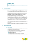
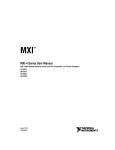
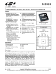
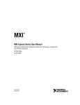
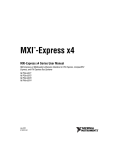
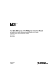
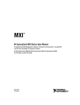
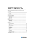
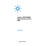
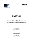
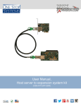
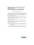
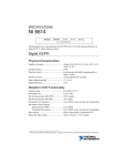
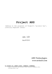
GETTING STARTED GUIDE NI PXImc Devices NI PXIe-8383mc PXImc Adapter Module Contents About This Guide ..................................................................................................................... 1 Products Covered.............................................................................................................. 1 Related Documentation .................................................................................................... 2 Conventions ...................................................................................................................... 2 Electromagnetic Compatibility Guidelines .............................................................................. 2 Functional Overview ................................................................................................................ 3 Product Features ....................................................................................................................... 5 LED Indicators ................................................................................................................. 7 Installation and Configuration .................................................................................................. 8 Unpacking......................................................................................................................... 8 Hardware Installation ....................................................................................................... 8 Cabling.............................................................................................................................. 9 Powering On the PXImc System ...................................................................................... 10 Powering Off the PXImc System ..................................................................................... 12 Software Installation and Configuration........................................................................... 12 Specifications............................................................................................................................ 13 Worldwide Support and Services ............................................................................................. 16 About This Guide This document describes the features, functions, and operation of the NI PXIe-8383mc PXImc adapter module. Products Covered • NI PXIe-8383mc (153100x-02L) The model number listed below is followed by the specific NI assembly number in parentheses. Ensure the specifications of interest match the NI assembly number that is printed on either the front or back side of the board. Note Note x denotes all letter revisions of the assembly. Related Documentation The following documents contain information that you might find helpful as you read this manual: • Your computer or chassis documentation • MXI-Express Gen II x8 User Manual available on the ni.com website • NI-PXImc™ Help file included with NI-PXImc driver • PXI Express Hardware Specification, Revision 2.0 • PXI-6 PXI Express Software Specification • PICMG CompactPCI Express EXP.0 R1.0 Specification • PCI Express Specification, Revision 2.0 • PCI Express External Cabling 2.0 Specification • PXI MultiComputing Hardware Specification, Revision 1.0 • PXI MultiComputing Software Specification, Revision 1.0 Conventions The following conventions appear in this manual: CompactPCI Express/ CPCIe The terms CompactPCI Express and CPCIe are interchangeable in this guide. MXI-Express Gen II x8 A NI PCIe-8381, NI PXIe-8381, NI PXIe-8384, or NI PXIe-8383mc product board. PCI Express/PCIe The terms PCI Express and PCIe are interchangeable in this guide. PXI Express chassis In this manual, whenever a PXI Express chassis is referenced, a CompactPCI Express chassis could be used instead. PXI Express/PXIe The terms PXI Express and PXIe are interchangeable in this guide. Electromagnetic Compatibility Guidelines This product was tested and complies with the regulatory requirements and limits for electromagnetic compatibility (EMC) stated in the product specifications. These requirements and limits provide reasonable protection against harmful interference when the product is operated in the intended operational electromagnetic environment. This product is intended for use in industrial locations. However, harmful interference may occur in some installations, when the product is connected to a peripheral device or test object, or if the product is used in residential or commercial areas. To minimize interference with radio and television reception and prevent unacceptable performance degradation, install and use this product in strict accordance with the instructions in the product documentation. 2 | ni.com | NI PXIe-8383mc Getting Started Guide Furthermore, any modifications to the product not expressly approved by National Instruments could void your authority to operate it under your local regulatory rules. To ensure the specified EMC performance, operate this product only with shielded cables and accessories. Caution Functional Overview The NI PXIe-8383mc is a PXImc adapter1 module that allows the attachment of sub-systems such as stand-alone instruments, PCs, or other PXI-Express systems to an existing PXI-Express system via a high-bandwidth, low-latency cabled MXI-Express x8 link2. The NI PXIe-8383mc contains a PXImc Logic Block that makes it possible to join systems together non-transparently. Figure 1 illustrates where the PXImc Logic Block is applied to join the Root Complexes of two systems. Figure 1. PXImc System Diagram PXImc Device Primary System Host MC CPU Memory Memory CPU Root Complex Root Complex Endpoint Endpoint Endpoint Endpoint Bridge NTB Endpoint PXImc Logic Block Physical Expansion Slot/Port Endpoint Endpoint Endpoint In the example shown, the system on the right is designated as a PXImc Device since it contains the PXImc Logic block (i.e. the NI PXIe-8383mc). The system on the left is designated the Primary System Host, which serves as the central connection hub for all other PXImc Devices. 1 2 Refer to Chapters 1 and 2 of the PXI-7 PXI MultiComputing Hardware Specification Revision 1.0 available on the pxisa.org website for relevant terminology and concepts used in this guide. The MXI-Express link is compatible with the PCI Express External Cabling 2.0 Specification developed by the PCISIG. NI PXIe-8383mc Getting Started Guide | © National Instruments | 3 This effectively creates a tree (or Star) connection topology as shown in the example connectionscenario in Figure 2. Figure 2. Example PXImc System Primary System Host 1 2 3 3 3 MC 2 1 3 Logical PXImc Device 6 4 MC PXImc Sub-system MC PXImc Device 5 MC PXImc Device 1 Embedded Controller 4 2 NI PXIe-8383mc in peripheral slot 5 PXI Express System Acting as a PXImc Device NI PXIe-8381 in controller slot 3 NI PXIe-8384 in peripheral slot 6 NI PCIe-8381in PCI Express Slot Figure 2 shows how various types of sub-systems can be connected to a Primary System Host to create a tree topology of PXImc Devices. The cable ports of all PXImc Logic Blocks in the example are indicated by an “mc” glyph to show their locations. In cases where a sub-system does not contain a PXImc Logic Block, a NI PXIe-8383mc can be installed in the Primary System Host to create a Logical PXImc Device out of the sub-system. Consolidating all NI PXIe-8383mc adapter modules into a single PXI-Express chassis, ideally the Primary System Host, will simplify the power sequence of the overall PXImc system. Tip 4 | ni.com | NI PXIe-8383mc Getting Started Guide The NI PXIe-8383mc can directly connect to any of the following NI MXI-Express Gen 2 x8 products. • NI PCIe-8381—Used to connect PCs with Gen 2 x8 or wider PCI-Express slots • NI PXIe-8384—Used to connect PXI-Express systems Refer to the MXI-Express Gen II x8 User Manual available on the ni.com website for installation instructions for the NI PCIe-8381, NI PXIe-8381, and NI PXIe-8384. Refer to the NI-PXImc Help file and readme.html files included with the NI-PXImc driver for feature updates. Product Features Figure 3 illustrates the core function and onboard features of the NI PXIe-8383mc. Figure 3. NI PXIe-8383mc (153100x-02L) Block Diagram 1 Link Good FP BP Link Activity FP BP Endpoint PCIe Gen II x8 PCIe NTB Endpoint PXImc Logic Block 7 PCIe Gen II x8 2 6 5 3 4 1 Onboard Status LEDs 5 Front Panel Link 2 Backplane Link 6 “mc” Cable Port 3 SW 4—FACT/USER Mode Switch 7 SW 5—CFC/SSC Mode Switch 4 SW 3—MC/DC Mode Switch The PXImc logic block consists of a non-transparent bridge and all the associated circuitry necessary to work with clock references from both the Primary System Host and the PXImc Device’s own sub-system. The non-transparent bridge (NTB) isolates the processor and resources in the Primary System Host from those in the sub-system. The NTB is recognized as a PCI Express system endpoint to each of the systems. As a result, devices and other PCI resources on either side of the NTB are not visible to each other. Communication between the NI PXIe-8383mc Getting Started Guide | © National Instruments | 5 two systems occurs through processor domain partitioning and address translation between the memory-mapped spaces of the two processors. Each side of the PXImc logic block is connected to the front panel “mc” cable port and backplane connectors. For optimum link widths and performance, use the NI PXIe-8383mc in chassis that support a Gen 2 x8 backplane link. The chassis should also be controlled by a Slot 1 controller with Gen 2 x8 links to the backplane. National Instruments offers Gen 2 PXI Express chassis and controllers that can establish x8 links. Tip Onboard Switches The NI PXIe-8383mc contains the following onboard switches. SW3—MC / DC Mode Switch The NI PXIe-8383mc is a multi-personality product capable of operating in either multi-computing (MC) mode or daisy-chain (DC) mode. This makes it possible for an NI PXIe-8383mc in MC mode to connect to another NI PXIe-8383mc in DC mode, just as if it were a NI PXIe-8384 daisy-chain module. National Instruments recommends operating the NI PXIe-8383mc in MC mode, and using a NI PXIe-8384 for daisy-chain purposes. . MC / DC Mode Switch SW3 MC (Default) PXImc Logic Block mode DC Daisy-chaining mode* * NI recommends using the NI PXIe-8384 instead of an NI PXIe-8383mc set to DC mode since this feature may be removed in the future. SW4—FACT / USER (Factory / User) Mode Switch The FACT/USER switch shown in Figure 3 selects between two different memory resource request sizes. With the switch in the FACT position the NI PXIe-8383mc requests a minimal amount of system resources and should be compatible with most computer systems that try to connect to it. With the switch in the USER position the NI PXIe-8383mc requests a greater amount of system resources which may affect system compatibility. Depending on your application, USER mode may provide better system performance. Refer to the NI-PXImc Help file included with the NI-PXImc driver for more information on this topic. Some BIOSes may have trouble allocating the resources requested by the NI PXIe-8383mc set to USER mode. The BIOSes of high performance NI embedded controllers such as the NI PXIe-8133 and NI PXIe-8135 have been designed with this in mind and offer maximum system compatibility. Note 6 | ni.com | NI PXIe-8383mc Getting Started Guide This switch has no affect when SW3 is in DC mode. FACT / USER Switch (Factory / User) BAR No. Size (bytes) Address Space Prefetchable? BAR 5 32M 32-bit Yes BAR 1 128M 32-bit Yes BAR 2 64M 64-bit Yes BAR4 16M 32-bit No BAR5 32M 32-bit Yes FACT SW4 USER SW5—CFC/SSC Clocking Mode Switch When the board operates in daisy chain (DC) mode this switch determines the clocking mode for the front panel cable port. NI recommends keeping this switch in the default SSC mode unless otherwise specified. Regardless of the clock mode selected, the reference clock is PCI Express Gen 2 specification compliant. This switch has no affect when SW3 is in MC mode. CFC / SSC Switch SW5 CFC 100 MHz Constant Frequency Clock SSC (Default) 100 MHz Spread Spectrum Clock with 0.5% downspread LED Indicators The LEDs on the NI PXIe-8383mc give status information about power supplies, link state, and mode of operation. Table 1 describes the function of the front panel LEDs. Table 1. Front Panel LED Status Descriptions of the NI PXIe-8383mc LED Color PWR/LINK Off MC Meaning Power is off Blinking Red Power is out of spec Solid Amber Power is on and within spec; an electrical link has not been established with the front panel and/or the chassis backplane Solid Green Power is on and within spec; electrical links have been established with both the front panel and backplane ports off Daisy Chain mode Solid Green PXImc mode NI PXIe-8383mc Getting Started Guide | © National Instruments | 7 There are also onboard LEDs that report more specific link status which can be useful for debugging cases when the front panel PWR/LINK LED reports a solid amber status. Link Good LEDs—LEDs that indicate a successful front panel cable link (LED FP) and backplane link (LED BP) to the onboard PCIe NTB switch. Link Activity LEDs—LED that indicates link activity on the backplane link (LED BP). Refer to Figure 3 for the location of these LEDs. Installation and Configuration This section explains how to unpack and install the NI PXIe-8383mc hardware and software. Unpacking The NI PXIe-8383mc is shipped in antistatic packages to prevent electrostatic discharge (ESD) to the devices. ESD can damage several components on the device. Caution Never touch the exposed pins of connectors. Doing so may damage the device. To avoid such damage in handling the device, take the following precautions: • Ground yourself using a grounding strap or by holding a grounded object. • Touch the antistatic package to a metal part of the computer chassis before removing the device from the package. Remove the device from the package and inspect the device for loose components or any sign of damage. Notify NI if the device appears damaged in any way. Do not install a damaged device into the computer or into a PXI Express or CompactPCI Express chassis. Store the device in the antistatic envelope when not in use. Hardware Installation The following are general instructions for installing the NI PXIe-8383mc. Consult your computer user manual or technical reference manual for further instructions and warnings. The protection provided by the MXI-Express Gen II x8 products can be impaired if it is used in a manner not described in this document. Caution Complete the following steps to install the NI PXIe-8383mc in your PXI Express or CompactPCI Express chassis. 1. 8 Power off your PXI Express or CompactPCI Express chassis, but leave it plugged in while installing the NI PXIe-8383mc. The power cord grounds the chassis and protects it from electrical damage while you install the module. | ni.com | NI PXIe-8383mc Getting Started Guide Caution To protect both yourself and the chassis from electrical hazards, leave the chassis off until you finish installing the NI PXIe-8383mc. 2. Remove or open any doors or covers blocking access to the slot in which you intend to install the NI PXIe-8383mc. 3. Touch a metal part of the chassis to discharge any static electricity that might be on your clothes or body. 4. Make sure the injector/ejector handle is in its downward position. Be sure to remove all connector packaging and protective caps from retaining screws on the module. 5. Identify which slot the NI PXIe-8383mc will be installed in the chassis. Refer to Table 2 to determine which slot types the NI PXIe-8383mc is compatible with. Table 2. NI PXIe-8383mc Slot Type Compatibility PXI Express Chassis NI PXI Express Product NI PXIe-8383mc 6. Controller Hybrid Peripheral H — ✓ ✓ Align the NI PXIe-8383mc with the card guides on the top and bottom of the system controller slot. Hold the handle as you slowly slide the module into the chassis until the handle catches on the injector/ejector rail. Caution Do not raise the injector/ejector handle as you insert the NI PXIe-8383mc. It will not insert properly unless the handle is in its downward position so that it does not interfere with the injector/ejector rail on the chassis. 7. Raise the injector/ejector handle until the module firmly seats into the backplane receptacle connectors. The front panel of the NI PXIe-8383mc should be even with the front panel of the chassis. 8. Tighten the bracket-retaining screws on the top and bottom of the front panel to secure the NI PXIe-8383mc to the chassis. 9. Replace or close any doors or covers to the chassis. Cabling National Instruments offers a variety of shielded MXI-Express x8 copper cables that can be used to connect the NI PXIe-8383mc to MXI-Express Gen 2 x8 products. The NI MXI-Express x8 copper cables use Molex x8 PCIe connectors, and have no polarity, so either end can be connected to either product. For more information about these connectors visit Molex at www.molex.com and search for x8 PCIe iPass. NI PXIe-8383mc Getting Started Guide | © National Instruments | 9 Table 3 shows the various MXI-Express x8 copper cables available from National Instruments. Table 3. National Instruments MXI-Express x8 Copper Cables Cable Length (Meters) Description Part Number 3m MXI-Express x8 copper cable 782317-03 5m MXI-Express x8 copper cable 782317-05 Do not insert or remove the cable after either system is powered on. Doing so can hang or cause errors in applications communicating with devices. If a cable becomes unplugged, plug it back into the system. You will need to restart both systems. Caution Powering On the PXImc System The order that systems are powered on relative to each other is important to ensure proper operation. BIOSes and operating systems make the assumption that all PCI devices in the entire hierarchy will be available as soon as the boot sequence begins. In addition, the non-transparent bridge in the PXImc Logic Block needs time to self-configure before the sub-system on the other side of the cable link can connect to it. Consolidating all NI PXIe-8383mc adapter modules into a single PXI-Express chassis, ideally the Primary System Host, will simplify the power sequence of the overall PXImc system. Simply power on the Primary System Host that contains all of the NI PXIe-8383mc adapter modules, and then power on all of the sub-systems that are cabled to it. For more complex PXImc System topologies, a simple approach to powering on all systems is to perform the following steps. 1. Power on all systems and chassis and allow the operating systems to fully load. 2. Reboot all systems. 10 | ni.com | NI PXIe-8383mc Getting Started Guide To avoid having to reboot system controllers and PCs, use the A to D power-on sequence illustrated in Figure 4. Figure 4. Power Sequence for an Example PXImc System Primary System Host 1 2 3 3 3 C MC 2 1 3 Logical PXImc Device B 6 D 4 MC PXImc Sub-system A MC B 5 MC PXImc Device B PXImc Device 1 Embedded Controller 4 2 NI PXIe-8383mc in peripheral slot 5 PXI Express System Acting as a PXImc Device NI PXIe-8381 in controller slot 3 NI PXIe-8384 in peripheral slot 6 NI PCIe-8381in PCI Express Slot 1. Power on all daisy-chained PXI or PXI-Express chassis that are not controlled by an embedded controller, and do not have cable links with “mc” ports involved. The item that follows power sequence A in Figure 4 meets these criteria. 2. Power on any applicable PXI-Express chassis and/or PCs that contain ‘mc’ cable ports (for example, the NI PXIe-8383mc) but are not cabled to other sub-systems that contain “mc” port(s) and are still powered off. Allow time for the operating system to begin loading before proceeding to the next step. The three items that follow power sequence B in Figure 4 meet these criteria. Do not power on any chassis or PCs if it they are cabled to “mc” port(s) in other systems that are powered off. Doing so will prevent the PXImc Logic Block(s) from recognizing the system that is cabled to it, and the system that contains the PXImc Logic Block(s) will need to be rebooted to resolve this issue. Caution NI PXIe-8383mc Getting Started Guide | © National Instruments | 11 3. Power on the sub-system(s) that are on the other side of the cable link(s) of the system(s) that were powered on in Step 2. These sub-systems may also contain additional “mc” ports for cable links to other sub-systems. The item that follows power sequence C in Figure 4 meets this criterion. 4. Repeat Step 3 if applicable until all systems are powered on. The item that follows power sequence D in Figure 4 meet this criterion. 5. Observe the front panel Link LED status on all NI PXIe-8383mc modules and all other products that connect the chassis and systems together via a cable link. A properly linked system should report a solid green status across all products that accept a cabled MXI-Express connection. All NI PXIe-8383mc adapter modules should report a solid green MC LED status wherever they are set to MC mode of operation. The front panel LED status of the NI PXIe-8383mc may not report cases when systems are not properly recognized due to an improper power on sequence. A reboot of the system that controls the NI PXIe-8383mc may be necessary to resolve this. Caution In applications where the power sequence must be automated, consider using products with Wake-on-LAN features or NI chassis that have Inhibit Mode capability. Be sure to allow time in the sequence for the NI PXIe-8383mc to configure prior to powering on the sub-system that is cabled to it. Tip Powering Off the PXImc System The correct power off sequence is the reverse of the power on sequence illustrated as D to A in Figure 4. Make sure that all data transfer applications through all PXImc Logic Blocks are stopped before proceeding. Be sure to power off sub-systems that are cabled to “mc” ports of other systems first. Following an improper power off sequence may cause the operating system(s) of involved systems to hang or fail. Caution To power off the chassis while the host computer or host chassis is on, you may need to hold the power button for at least four seconds. Note Software Installation and Configuration The NI PXImc-8383mc requires the NI-PXImc driver software to enable its features. Refer to the readme.html on the NI-PXImc driver DVD for software installation instructions. 12 | ni.com | NI PXIe-8383mc Getting Started Guide Specifications This section lists the system specifications for the following products only: • NI PXIe-8383mc (153100x-02L) The model numbers listed are followed by their specific NI assembly numbers in parentheses. Ensure the specifications of interest match the NI assembly number that is printed on either the front or back side of the board. Note Note x denotes all letter revisions of the assembly. Refer to the MXI-Express Gen II x8 Series User Manual for specifications on the NI PCIe-8381, NI PXIe-8381, and NI PXIe-8384 products. NI PXIe-8383mc (153100x-02L) Note These specifications are typical at 25 °C, unless otherwise stated, and are subject to change without notice. Physical Dimensions ....................................................... 10.0 × 16.0 cm (3.9 × 6.3 in.) Maximum cable length ..................................... 5 m copper Slot requirements.............................................. One peripheral slot (PXI Express or CompactPCI Express) Compatibility .................................................... Fully compatible with the PXI Express Hardware Specification, Revision 2.0, PICMG CompactPCI Express EXP.0 R2.0 Specification, PCIe External Cable Specification, and the PXI MultiComputing Hardware 1.0 Specification. Weight............................................................... 0.17 kg (0.37 lb) typical Power Requirements * Power Rail Typical Current Maximum Current +3.3 V 570 mA* 900 mA* +12 V 620 mA 1000 mA +5 VAux 5 mA 20 mA Not including the power consumed by an active cable. NI copper cables (782317-0x) are passive. NI PXIe-8383mc Getting Started Guide | © National Instruments | 13 Environment Maximum altitude.............................................2,000 m Pollution Degree ...............................................2 Indoor use only. Operating Environment Ambient temperature range ..............................0 to 55 °C (Tested in accordance with IEC-60068-2-1 and IEC-60068-2-2. Meets MIL-PRF-28800F Class 3 low temperature limit and MIL-PRF-28800F Class 2 high temperature limit.) Relative humidity range....................................10 to 90%, noncondensing (Tested in accordance with IEC-60068-2-56.) Storage Environment Ambient temperature range ..............................-40 to 71 °C (Tested in accordance with IEC-60068-2-1 and IEC-60068-2-2. Meets MIL-PRF-28800F Class 3 limits.) Relative humidity range....................................5 to 95%, noncondensing (Tested in accordance with IEC-60068-2-56.) Shock and Vibration Operational shock .............................................30 g peak, half-sine, 11 ms pulse (Tested in accordance with IEC-60068-2-27. Meets MIL-PRF-28800F Class 2 limits.) Random Vibration Operating ..........................................................5 to 500 Hz, 0.3 grms Nonoperating ....................................................5 to 500 Hz, 2.4 grms (Tested in accordance with IEC-60068-2-64. Nonoperating test profile exceeds the requirements of MIL-PRF-28800F, Class 3.) Clean the NI PXIe-8383mc with a soft nonmetallic brush. Make sure that the device is completely dry and free from contaminants before returning it to service. Caution 14 | ni.com | NI PXIe-8383mc Getting Started Guide Safety This product meets the requirements of the following standards of safety for electrical equipment for measurement, control, and laboratory use: • IEC 61010-1, EN 61010-1 • UL 61010-1, CSA 61010-1 For UL and other safety certifications, refer to the product label or the Online Product Certification section. Note Electromagnetic Compatibility This product meets the requirements of the following EMC standards for electrical equipment for measurement, control, and laboratory use: • EN 61326-1 (IEC 61326-1): Class A emissions; Basic immunity • EN 55011 (CISPR 11): Group 1, Class A emissions • AS/NZS CISPR 11: Group 1, Class A emissions • FCC 47 CFR Part 15B: Class A emissions • ICES-001: Class A emissions Note In the United States (per FCC 47 CFR), Class A equipment is intended for use in commercial, light-industrial, and heavy-industrial locations. In Europe, Canada, Australia and New Zealand (per CISPR 11) Class A equipment is intended for use only in heavy-industrial locations. Group 1 equipment (per CISPR 11) is any industrial, scientific, or medical equipment that does not intentionally generates radio frequency energy for the treatment of material or inspection/analysis purposes. Note Note For EMC declarations and certifications, and additional information, refer to the Online Product Certification section. CE Compliance This product meets the essential requirements of applicable European Directives as follows: • 2006/95/EC; Low-Voltage Directive (safety) • 2004/108/EC; Electromagnetic Compatibility Directive (EMC) Online Product Certification To obtain product certifications and the Declaration of Conformity (DoC) for this product, visit ni.com/certification, search by model number or product line, and click the appropriate link in the Certification column. NI PXIe-8383mc Getting Started Guide | © National Instruments | 15 Environmental Management NI is committed to designing and manufacturing products in an environmentally responsible manner. NI recognizes that eliminating certain hazardous substances from our products is beneficial to the environment and to NI customers. For additional environmental information, refer to the Minimize Our Environmental Impact web page at ni.com/environment. This page contains the environmental regulations and directives with which NI complies, as well as other environmental information not included in this document. Waste Electrical and Electronic Equipment (WEEE) At the end of the product life cycle, all products must be sent to a WEEE recycling center. For more information about WEEE recycling centers, National Instruments WEEE initiatives, and compliance with WEEE Directive 2002/96/EC on Waste Electrical and Electronic Equipment, visit ni.com/ environment/weee. EU Customers ⬉ᄤֵᙃѻક∵ᶧࠊㅵ⧚ࡲ⊩ ˄Ё RoHS˅ Ёᅶ᠋ National Instruments ヺড়Ё⬉ᄤֵᙃѻકЁ䰤ࠊՓ⫼ᶤѯ᳝ᆇ⠽䋼ᣛҸ (RoHS)DŽ݇Ѣ National Instruments Ё RoHS ড়㾘ᗻֵᙃˈ䇋ⱏᔩ ni.com/ environment/rohs_chinaDŽ (For information about China RoHS compliance, go to ni.com/environment/rohs_china.) Worldwide Support and Services National Instruments corporate headquarters is located at 11500 North Mopac Expressway, Austin, Texas, 78759-3504. National Instruments also has offices located around the world. For telephone support in the United States, create your service request at ni.com/support or dial 512 795 8248. For telephone support outside the United States, visit the Worldwide Offices section of ni.com/niglobal to access the branch office websites, which provide up-to-date contact information, support phone numbers, email addresses, and current events. Refer to the NI Trademarks and Logo Guidelines at ni.com/trademarks for more information on National Instruments trademarks. Other product and company names mentioned herein are trademarks or trade names of their respective companies. For patents covering National Instruments products/technology, refer to the appropriate location: Help»Patents in your software, the patents.txt file on your media, or the National Instruments Patents Notice at ni.com/patents. You can find information about end-user license agreements (EULAs) and third-party legal notices in the readme file for your NI product. Refer to the Export Compliance Information at ni.com/legal/export-compliance for the National Instruments global trade compliance policy and how to obtain relevant HTS codes, ECCNs, and other import/export data. © 2013 National Instruments. All rights reserved. 374141A-01 Aug13