1
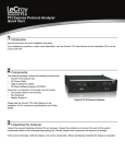
Eclipse X34
MIPI M-PHY® Protocol Analyzer
Quick Start
1 Introduction
Use this document for quick installation and setup.
If you experience problems or need more information, see the User Manual on the Installation CD or at the Teledyne
LeCroy web site.
2 Components
The analyzer package includes the following components:
• Eclipse X34 analyzer system
• DC Power Adapter (12 volts) and AC power cable
• USB cable
• Teledyne LeCroy Equipment Carrying Pouch
• Software program CD-ROM
Please see the Eclipse X34 User Manual on the installation
CD for component specifications and further details. There
is a version of this manual on the CD that corresponds to
the M-PHY technology you chose (M-PCIe, SSIC, etc.).
Each purchased M-PHY technology (M-PCIe, SSIC, etc.)
ships with a CD-ROM that corresponds to that technology.
3
Eclipse X34 Protocol Analyzer
Unpacking the Analyzer
Inspect the received shipping container for any damage. Unpack the container and account for each of the system
components listed on the accompanying packing list. Visually inspect each component for absence of damage.
In the event of damage, notify the shipper and Teledyne LeCroy. Retain all shipping materials for shipper’s inspection.
4
Front Panel Description
1 2 3 4
5
6
7
8
9 10
11
The Analyzer has the following features on the front:
[1] Power LED: Lights when power is On.
[2] Status LED: Displays the connection status of the link.
Red -
Error condition. Try using the application to
clear the error. Please contact the factory if
this does not work.
Lanes are currently showing activity.
[9] Gear LEDs: Indicates current gear the analyzer is using for
the Downstream direction.
[10] Ref Clk In (Reference Clock In): Provides an optional
alternative connection from an external reference clock
source to the Eclipse X34 analyzer Downstream direction.
Note: In standard configuration, the Eclipse X34 analyzer uses
the reference clock from a probe cable from the interposer.
[11] Trigger In and Out: Provide external trigger capabilities.
You can configure Eclipse X34 to trigger external equipment
using Trigger Out. You can use Trigger In to trigger the
Analyzer from another device.
Rear Panel Description
Green - Configuring system.
Blue -
Unit ready/connected.
[3] Trigger LED: Lights when Eclipse X34 triggers on an event.
[4] Ref Clk In (Reference Clock In): Provides an optional
alternative connection from an external reference clock
source to the Eclipse X34 analyzer Upstream direction.
Note: In standard configuration, the Eclipse X34 analyzer
uses the reference clock from a probe cable from the
interposer.
[5] GEAR LEDs: Indicates current gear the analyzer is using for
the Upstream direction.
Green - Detected Speed.
[6] Upstream [3:0] LEDs: Indicates which Upstream Lanes are
currently showing activity.
Green - Activity detected with no error.
Orange - Activity detected with error.
Blank - No activity detected.
[7]
Upstream [3:0] and Downstream [3:0] connector:
Connection to the probe for the capture of both upstream and
downstream directions of the link.
[8] Downstream [3:0] LEDs: Indicates which Downstream
5 Interposers and Probes
1
2
3
4
5
6
The rear panel of the Analyzer has:
[1] x8 Expansion: Used to connect two X34 systems using a
special cable to record X8 traffic.
[2] Sync /Data: Use a special cable to allow multiple Teledyne
LeCroy analyzers to send synchronization and
control messages to one another. This
connection is also required for x8 Expansion.
[3] Ethernet Port: 1 GIGE Connectivity allows connection to the
analyzer through an Ethernet network.
[4] USB Type B Host Machine Connector: To connect the
Analyzer to the host machine using a USB connection.
[5] DC IN: 12V, 8A
[6] Power Switch (black): 1 = On and 0 = Off
Warning:
Do not open the enclosure. No operator serviceable
parts are inside.
The Eclipse X34 supports a full range of Teledyne LeCroy MPHY
Interposers and Probes, including:
SMA Interposer: Supports lane widths from x1 to x4 at data rates
for GEAR1/2/3.
Multi-lead Probe: Supports lane widths from x1 to x4 at data
rates for GEAR1/2/3 on the X34 system.
Warning:
Interposer has static-sensitive components.
Handle only at static-safe work stations.
6 Installing the Software
The software operates all of Teledyne LeCroy’s PCI Express Protocol Analyzer and Exerciser products and should be installed on a
Microsoft® Windows®-based host machine. You need to install the software on the host machine before attaching the X34 Analyzer to the
system. The software suite corresponds to the M-PHY technology you chose at purchase time. If you selected M-PCIe, you will use the
PCIe Protocol Suite. For SSIC, this would be USB Protocol Suite, and so on.
The minimum requirements for the host machine are:
•
Microsoft Windows 8, Windows Server 2012, Windows 7, Windows Server 2008R2, Windows XP operating systems.
•
2 GB of RAM.
•
Storage with at least 200MB of free space for the installation of the software and additional space for recorded data.
•
Display with resolution of at least 1024x768 with at least 16-bit color depth.
•
USB2.0 port and/or 100/1000Mbps Ethernet network interface.
For optimal performance, please refer to our recommended configuration in the product documentation
In general, the higher the performance of the host machine, the better user experience you get. Please refer to the Readme notes and
User Manual for recommended configurations and additional information. User manuals for your Teledyne LeCroy MPHY products can
be found in:
Start > All Programs > LeCroy > XXX Protocol Suite > XXX Protocol Suite
Note: XXX Protocol Suite is dependent on the software package suite the customer orders with the Eclipse X34.
To install the software, follow the steps below:
1. Insert the CD into the CD-ROM drive of the host machine that will control the Analyzer. The installation window opens and displays
links to the software installation, user manuals, application notes, and data sheets.
2. Select Install XXX Protocol Suite and follow the on-screen instructions. The software installs automatically on the host machine’s
hard disk. During installation, all necessary USB drivers will be installed.
3. To start the application, launch the software program from the Start menu:
Start > All Programs > LeCroy > XXX Protocol Suite > XXX Protocol Suite
Software installation can also be downloaded from the Teledyne LeCroy website.
7 Setting Up and Connecting the Eclipse X34 Analyzer
You can connect the Analyzer to the host machine using USB or Ethernet.
Using an Ethernet Connection
To set up the Analyzer using an Ethernet connection:
1. Install software on the host machine.
2. Connect the Analyzer to a 100-volt to 240-volt, 50 Hz to
60 Hz, 120 W power outlet using the provided power cord.
3. Connect the Ethernet cable between the Ethernet port on the
Analyzer and a Ethernet port in the local network.
4. Turn on the power switch on the front of the analyzer.
Note 1: No driver installation is needed for Eclipse X34 to operate
over a network.
Note 2: Eclipse X34 is configured at the factory to use dynamic IP
setting and will get all required network parameters from the
DHCP server on your network. If the DHCP server is not
available, or to connect Eclipse X34 directly to the host
machine, you can reconfigure the network settings of Eclipse
X34 using the menus in the LCD display on the front of the
analyzer (see the “LCD Menus” part of section 4 of this
document).
Connecting to Eclipse X34 in the software
Start the software and perform the following procedure to connect
to a Eclipse X34 analyzer over the network.
1. Select the Setup > All connected devices… menu in the
application to display the Analyzer Devices dialog.
2.
The Eclipse devices in the list are marked:
•
Locked: Some other client on the network is already
connected to that device
•
Ready to connect: Available for connection
Select your Eclipse X34 device in the list and press the
Connect button to execute the connection procedure. After
the connection is established, the application displays the
Connection Properties dialog.
3.
Select an option:
•
Automatically connect to the device: When the
application is started or when the named device appears
on the network while the application is running on this
computer, the application will try to connect to the named
device.
•
Ask if I want to connect to the device: When the
application is started or when the named device appears
on the network while the application is running on this
computer, the application will display a message box
allowing you to connect to the named device.
•
Take no action: When you start the application or when
the named device appears on the network while the
application is running on this computer, you must
connect manually to use the named device.
Note: When you close the application on this computer (or
you perform manual disconnect), the application
disconnects from the device.
4. Press OK in the Connection Properties dialog. After you
finish the connect procedure, the Eclipse X34 to which you
have connected is marked as Ready and you can use it for
recording.
Note:
Note:
To disconnect from a device, display this dialog,
select the device, and click the Disconnect button.
Eclipse X34 will not appear in the Analyzer Device dialog
if it is connected on a different Subnet on your local
network. You can connect to it on the Subnet by
specifying its IP address in the Add Device dialog.
Using a USB Connection
5.
To set up the Analyzer using a USB connection:
1. Install software on the host machine.
2. Connect the Analyzer to the 12-volt DC Adaptor provided in
the box.
3. Connect the USB port to a USB port on the host machine
using a USB cable.
4. Turn on the power switch on the back of the Analyzer.
Note: At power-on, the Analyzer initializes and performs a
self-diagnostic. If failure occurs, call Teledyne LeCroy
Customer Support for assistance.
6.
Eclipse X34 will be recognized by the host machine as a USB
device.
Follow the Microsoft® Windows® on-screen Plug-and-Play
instructions for the automatic installation of the Analyzer as a
USB device on your analyzing host machine. (The required
USB drivers are included on the Installation CD and were
installed on your system when you installed the software.)
Click Finish when you see the message that says “Windows
has finished installing the software that your new hardware
requires” and the file has been installed in your host machine.
Start the software, so you can start working with Eclipse X34.
8 Making Your First Recording
Connect Eclipse X34 to the system under test using an interposer or probe, and then configure the Recording Options.
You can then test the Analyzer by creating a short snapshot recording.
Connect Eclipse X34 to System under Test using an Interposer or Probe
For an SMA Probe/Interposer, do the following:
1. Connect the SMA Cables between the two Devices under test so that the data paths
travel through the appropriate connections on the SMA Probe.
2. Connect power to the interposer using the provided 12-V power adapter.
For a multi-lead probe or other types of probes and interposers, please see the User Manual.
Configure Recording Options
1. From the Setup menu, select Recording Options.
2. Select the General tab and then choose Eclipse X34 as the Analyzer type.
3. In the Link section, specify the lane width of the MPHY link to be analyzed. The rest of the settings in this section can
be left at the factory defaults for most MPHY systems.
4. For multi-lane links, the Analyzer needs to observe link training to record link traffic correctly.
5. Click OK at the bottom of the Recording Options dialog box to apply the Analyzer recording settings specified.
Start Recording
1. Start a recording session by clicking the Record
button in the toolbar. Recording is tracked and reported on an
activity meter in the status bar.
2. After the recording buffer fills, uploading starts automatically. The MPHY traffic is saved to the hard drive as the file
specified in the recording options, and this file is opened in the application for you to view the traffic.
Note: You can interrupt a session by pressing the Stop button. If Recording is finished and Upload has started but has not
finished, a message box appears. You can:
• Continue uploading.
• Abort the upload and flush the data.
• Abort the upload and preserve all the previously saved data.
Teledyne LeCroy Customer Support
Online Download
Periodically check the Teledyne LeCroy Protocol Solutions Group
web site for software updates and other support related to this
product. Software updates are available to users with a current
Maintenance Agreement.
Trademarks and Servicemarks
Teledyne LeCroy and Eclipse X34 are trademarks of Teledyne
LeCroy.Microsoft and Windows are registered trademarks of
Microsoft Inc.All other trademarks are property of their respective
companies.
Mail:
Web:
E-mail:
Tel:
Tel:
Fax:
3385 Scott Blvd., Santa Clara, CA 95054-3115
teledynelecroy.com/Support/SoftwareDownload/
[email protected]
(800) 909-7112 (USA and Canada)
(408) 653-1260 (worldwide)
(408) 727-6622 (worldwide)
Changes
Product specifications are subject to change without notice.
Teledyne LeCroy reserves the right to revise the information in this
document without notice or penalty.
© 2014 Teledyne LeCroy, Inc. All rights reserved.
Part Number: 925030-00 Rev B
This document may be printed and reproduced without additional permission, but all copies should contain this copyright notice.