1
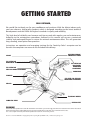
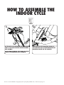
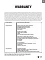
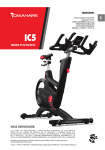
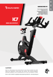
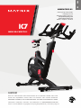
ENG
Indoorcycling Group GmbH
Happurger Str. 86
90482 Nuremberg | Germany
[email protected]
www.indoorcycling.com
Phone: +49(0)911 / 54 44 50
IC7
MODEL NO:IC-MXIC7B-01
CAUTION!
READ ALL PRECAUTIONS AND INSTRUCTIONS IN THIS MANUAL BEFORE YOU START
USING THIS EQUIPMENT. PLEASE KEEP THIS MANUAL FOR FUTURE REFERENCE.
IMPROPER ASSEMBLY, USE OR MAINTENANCE CAN VOID THE WARRANTY TERMS.
ADDITIONAL LANGUAGES AVAILABLE FOR DOWNLOAD AT WWW.INDOORCYCLING.COM
Version 1.0 2014 IC-MXIC7B-01 Copyright by Indoorcycling Group GmbH 2014 | www.indoorcycling.com
ESP
MANUFACTURED BY:
TABLE OF CONTENTS
IMPORTANT PRECAUTIONS P.3
GETTING STARTED P.4
HOW TO ASSEMBLE THE INDOOR CYCLE P.5-9
INSTALLATION AND DISPOSING OF BATTERIES P.10-11
HOW TO ADJUST THE INDOOR CYCLE P.12-14
HOW TO OPERATE THE INDOOR CYCLE P.15
PREVENTIVE MAINTENANCE P.16-19
MAINTENANCE ACTIVITY AND REQUIRED SCHEDULE P.20-21
SPARE PARTS P.22-34
WARRANTY P.35
TECHNICAL SPECIFICATIONS:
The Matrix IC7 indoor cycle is, according to EN ISO 20957 (1 & 10), a Class S product for
use in a controlled environment such as sports or fitness facilities
under the supervision of a trainer.
WEIGHT OF BIKE:
54 KG
MAX USER WEIGHT: 150 KG
USER HEIGHT:
SUITABLE FOR USERS BETWEEN APPROX. 155 AND 215 CM
REQUIRED FOOT PRINT:
APPROX. 132 X 52 CM
MAX SADDLE & HANDLEBAR HEIGHT:
APPROX. 120 CM
WARNING!
The performance data shown on the display exceeds the requirements according to DIN EN
957-5 for Class A ergometers. The average achieved accuracy of < +/- 1% relates to a rotational
speed range of 40 - 120 RPM and a braking efficiency of between 50 - 900 watts.
Electronic components adhere to the EMV Directive 204/108/EC, EMV Directive 99/519/EC,
and DIN EN 60335-1 for electrical safety.
Version 1.0 2014 IC-MXIC7B-01 Copyright by Indoorcycling Group GmbH 2014 | www.indoorcycling.com
ENG
IMPORTANT
PRECAUTIONS
WARNING!
To reduce the risk of serious injury due to improper
use of the equipment, carefully read and adhere
to the following important precautions and
information before operating the indoor cycle!
1. It is the responsibility of the owner to ensure
that all users are informed of all warnings
and precautions for proper use, and are only
authorized to use the bike independently after
being successfully briefed by a qualified trainer or
instructor.
2. Do not operate the bike until it has been properly
assembled and inspected as described in this
manual.
3. Keep the indoor cycle indoors, away from moisture
and dust. Do not place the indoor cycle outdoors in
a garage or covered patio or near water or pools.
Operating temperature of the indoor cycle has to
be between 15°C~ 40°C Celsius (59°~104°F) at max.
humidity of 65%.
4. Always place the bike on a stable, level surface.
If the bike is to be placed on a hardwood floor or
carpet, it is recommended to place a floor mat
beneath the bike, to protect the floor
from becoming damaged.
5. The level of safety of the indoor cycle can only
be guaranteed if it is regularly checked for possible
damage as well as wear and tear (e.g. fixing
points, E-Brake, Pedals, toe straps, etc.). Consult an
authorized service provider or the manufacturer
direct to ensure the regular inspections are properly
carried out.
6. Carry out all maintenance, care and service
procedures as described in this manual on a regular
basis. Defective parts must be replaced immediately,
and the device must not be used until the repairs
have been carried out.
Only use original parts from the manufacturer.
Repairs must only be carried out by from
manufacturer authorized service technicians.
7. Unsupervised children should be kept away from
the training device at all times.
8. Children under the age of 14 shall only be allowed
to use the indoor cycle with parental approval and
supervision of a qualified Trainer or Instructor. Use of
the bike by persons over the age of 14 only after they
are briefed by a qualified trainer or instructor.
9. The indoor cycle must not be used by persons
exceeding weight of 330 lbs/150 kg.
10. Always wear appropriate tight-fitting cycling
or athletic attire and sturdy shoes, preferably
cycling shoes, while operating the bike. Unfastened
shoelaces may become caught in the drive system
and lead to injury.
11. The indoor cycle does not have an
independently-moving flywheel. The pedals will
continue to move with the flywheel until the flywheel
stops. The movement can only be stopped by using
the emergency brake or by reducing the pedaling
frequency in a controlled manner. Always ride with
resistance load to ensure that your pedaling motion
is controlled. Do not adjust handlebar or saddle
during workout.
Do not pedal backwards.
12. If you feel pain or dizziness while exercising, stop
immediately. It is recommended that you consult
a doctor if the pain does not subside for an
extended period of time.
13. All data shown on the display, especially
the Watt values generated by the integrated
power sensor serve merely as information
and to help guide training. Only exercise
within your physical limitations.
WARNING!
If you have pre-existing health problems or a disability,
it is recommended that you consult your physician, in
order to find the training method which is best suited
to you. Incorrect or extensive training can result
in serious health injuries.
The manufacturer expressly assumes no responsibility for health
risks, personal injury, property damage or consequential damages
sustained by or through the use of this device, unless it is a case of
consequential damage which can be traced back to faulty material
and/or manufacturing, and which come under the responsibility of
the manufacturer.
3
GETTING STARTED
DEAR CUSTOMER,
We would like to thank you for your confidence and purchase. With the Matrix indoor cycle,
you have chosen a high-quality product, which is designed according to the latest technical
developments and thus fulfils the highest standards in quality and reliability.
This high level of reliability can however only be ensured with regular care and maintenance.
Adhering to the maintenance procedures outlined in this manual will ensure a maximised
stability and prolonged lifespan in return for minimal maintenance effort. This will guarantee
long-standing, interruption-free operation.
Instructions on operation and managing training for the Coach-by-Color® computer can be
found in the computer user manual also included with delivery.
SADDLE
FLIP LEVER FOR
HORIZONTAL SADDLE ADJUSTMENT
FLIP LEVER FOR
VERTICAL SADDLE ADJUSTMENT
RESISTANCE KNOB/
EMERGENCY BRAKE
FLIP LEVER FOR
HORIZONTAL
HANDLEBAR
ADJUSTMENT
HANDLEBAR
FLYWHEEL
FLIP LEVER FOR VERTICAL
HANDLEBAR ADJUSTMENT
SHROUD
TRANSPORT WHEELS
COMBI SPD PEDAL
WARNING!
LEVELING FEET
You will find the production code for the Matrix IC7 indoor cycle on the tag plate which is located on the lower left side of
the frame tube of the Indoor Bike. Please enter this production code into care and maintenance lists.
It is a strict requirement to provide the production code in all warranty claims.
Version 1.0 2014 IC-MXIC7B-01 Copyright by Indoorcycling Group GmbH 2014 | www.indoorcycling.com
ENG
HOW TO ASSEMBLE THE
INDOOR CYCLE
TORQUE WRENCH
17MM
2
PEOPLE
WARNING!
Avoid high fluctuations in temperature whilst transporting the bike from the store to the installation site.
If there are nevertheless large fluctuations in temperature, please allow the bike to acclimatise to the surrounding
temperature before proceeding with assembly.
1.
2.
50 NM
50 NM
WARNING!
Please ensure that bolts are tightened with significant force to minimize loosening
during use. If bolts are loosened after initial assembly, we recommend using
medium-strength LOCTITE® 243 when reassembling.
5
HOW TO ASSEMBLE THE
INDOOR CYCLE
2
PEOPLE
1.
SET THE VERTICAL ADJUSTMENT OF THE HANDLEBAR
STEM TO THE HIGHEST POSITION BEFORE BEGINNING
WITH ASSEMBLY.
2.
MAKE SURE THAT THE CONNECTING BRIDGES OF
THE HANDLEBARS ARE LOCATED UNDERNEATH THE
MOUNTING BRACKET FOR THE COMPUTER.
DO NOT REMOVE WARNING TAPE FROM THE SLIDERS
PRIOR TO THE HANDLEBAR BEING ASSEMBLED.
Version 1.0 2014 IC-MXIC7B-01 Copyright by Indoorcycling Group GmbH 2014 | www.indoorcycling.com
ENG
HOW TO ASSEMBLE THE
INDOOR CYCLE
TORQUE WRENCH
3.
6MM
2
PEOPLE
4.
30 NM
IN ORDER TO AVOID DAMAGING THE INTERIOR
CABLING, THE HANDLEBARS MUST NOT BE ADJUSTED
HORIZONTALLY BEFORE THIS STEP.
AFTER ASSEMBLY, REMOVE THE WARNING TAPE.
DO NOT MOVE HORIZONTAL SLIDER BACKWARDS.
ENSURE THAT BOLTS ARE TIGHTENED WITH
SUFFICIENT FORCE (30 NM) WHEN MOUNTING
THE HANDLEBARS.
THE FASTENING COUNTER SUNK BOLTS ARE COATED
WITH TUFLOK® AT THE FACTORY TO PREVENT THEM
FROM BECOMING LOOSE DURING USE.
IF BOLTS ARE LOOSENED AFTER INITIAL ASSEMBLY,
WE RECOMMEND USING HIGH-STRENGTH LOCTITE®
2701 WHEN REASSEMBLING.
7
HOW TO ASSEMBLE THE
INDOOR CYCLE
3MM
HAND TIGHT
2
PEOPLE
5.
OPEN THE FLIP LEVER FOR THE HORIZONTAL
ADJUSTMENT AND SLIDE THE HANDLEBARS
TO ITS MOST FORWARD POSITION.
ASSEMBLE THE BOTTOM END CAP.
6.
7.
CHECK THE HORIZONTAL ADJUSTMENT OF THE HANDLEBARS, WITH THE FLIP LEVER OPENED, FOR EASE OF MOTION
WHEN ADJUSTING.
CHECK THE CLAMPING FORCE OF THE HORIZONTAL ADJUSTMENT WITH THE FLIP LEVER CLOSED. MAKE SURE THE
HORIZONTAL ADJUSTMENT PERFORMS SUFFICIENTLY.
Version 1.0 2014 IC-MXIC7B-01 Copyright by Indoorcycling Group GmbH 2014 | www.indoorcycling.com
ENG
HOW TO ASSEMBLE THE
INDOOR CYCLE
1X
15 MM
PEDAL WRENCH
3MM
8.
HAND TIGHT
2
PEOPLE
9.
INSERT THE BIKE COMPUTER
INTO THE COMPUTER BRACKET.
FASTEN THE BIKE COMPUTER INTO PLACE FROM
THE UNDERSIDE OF THE HANDLEBARS WITH
THE BOLT AND PLASTIC SLEEVE PROVIDED.
WARNING!
The user manual for the IC7 Coach By Color® computer is enclosed separately and contains all the necessary information
for setting up and operating the computer.
10.
L
Attach the pedal marked R on the right
crank and tighten by turning clockwise (standard righthand thread). Attach the pedal marked L on the left crank
and tighten by turning counter-clockwise (left-hand
thread). Please make sure that both pedals are fastened
with sufficient force (55 NM), to ensure that the bolt does
not become loose during use.
The threads are provided with TufLok® at the factory
to prevent them from becoming loose during use.
If bolts are loosened after initial assembly, we
recommend using medium-strength LOCTITE® 243
when reassembling.
55 NM
R
WARNING!
OBSERVE ASSEMBLY
INSTRUCTIONS!
9
INSTALLATION AND
DISPOSING OF BATTERIES
Instructions stated in this manual must be performed during initial installation of the Matrix
indoor cycle in order to ensure optimal performance and a long lifespan. Please read and
follow the following instructions carefully. If the indoor cycles are not installed and configured
as described, the components may be subjected to excessive wear and tear and the bike may
become damaged. If you have any questions regarding installation,
please contact [email protected].
Please note: Lubricants are required for some maintenance procedures. Please only use an
acid- and solvent-free spray lubricant (e.g. Brunox) and white lithium grease.
1. Make sure the bike is level. If bike rocks on the floor, turn the levelling feet underneath the
front and/or rear stabilizer until the rocking motion is eliminated. Make sure that the levelling
feet are not screwed out further than 10 mm.
2. Verify emergency brake function to make sure that it is working properly.
3. Check that both crank arm Allen bolts, with which the cranks (on the right and left side of the
bottom bracket) are fastened, are secure (tightening torque 60 NM). These bolts are provided
with TufLok® at the factory to prevent them from becoming loose during use.
If the bolts become lose, we recommend applying medium-strength LOCTITE® 243 and then
reattaching the crank fixing bolts with a tightening torque of 60 NM.
4. Wipe down bike frame with a rag moistened with solvent-free spray lubricant.
5. Some parts of the bike may become loose during shipment. Check crank arms and all exposed
screws, bolts and nuts, and make sure that they are all secure and properly tightened.
Version 1.0 2014 IC-MXIC7B-01 Copyright by Indoorcycling Group GmbH 2014 | www.indoorcycling.com
ENG
INSTALLATION AND
DISPOSING OF BATTERIES
CUSTOMER SERVICE
1. Provide the customer with basic maintenance instructions, and direct them to detailed
maintenance instructions.
2. Have the sign-off sheet for the manual, explanation of maintenance procedures and
verification of impeccable condition of the bikes confirmed by the customer when handing over
the goods. A copy of this confirmation counter-signed by yourself is withheld by the customer.
3. Repairs must only be carried out by manufacturer authorised service technicians.
BATTERIES MAY NOT:
• come into contact with fire
• come into contact with coins or other metallic objects
If the device remains unused for an extended period of time, remove the battery in order to
avoid damage due to leakage or corrosion. If the battery leaks, remove all residues immediately
and insert a new battery. If you make contact with any residues, carefully remove them.
Products or batteries labelled with this symbol may not be disposed of along with normal
household refuse. For proper disposal, please find out about the applicable laws or guidelines
on disposing of electrical devices and batteries in your local area and adhere to them.
11
HOW TO ADJUST THE
INDOOR CYCLE
The Matrix indoor cycle can be very easily adjusted, depending on the requirements of various
user groups. This enables maximum riding comfort to be ensured whilst achieving optimal
training results. The configurations described in the following paragraphs demonstrate just a
few of the most often used adjustment variations of which the indoor cycle is capable. It is up to
the user to adjust the indoor cycle to a riding position best suited to their requirements.
ADJUSTING THE SEAT HEIGHT:
Sit on the saddle and ensure that your hip is not tilted to one side when the pedal has assumed
the position as shown in the picture. Place your shoes in the toe clips (cages) on the pedals,
or in the SPD cleats if you are using cycling shoes, if your indoor cycle is not fitted with a
combi pedal system.
VERTICAL SADDLE
ADJUSTMENT
VERTICAL HANDLEBAR
ADJUSTMENT
OPEN
OPEN
CLOSED
CLOSED
WARNING!
Do not adjust seat and handlebar during exercise. Ensure that all flip levers (vertical and horizontal) are closed, before you
sit on the bike and always step off the bike when making adjustments to the handlebars and/or saddle.
Start pedalling slowly, until the pedal has reached the position as shown in the picture. The vertical saddle sliders should
be adjusted so that your knees are always slightly bent when this pedal position is reached, without dropping your hip
one side. Rule of thumb: When standing next to the bike, the upper edge of the saddle should be a hand‘s width/four
fingers below your iliac crest. Please avoid cycling with your knees fully extended or your hip tilted to one side.
Version 1.0 2014 IC-MXIC7B-01 Copyright by Indoorcycling Group GmbH 2014 | www.indoorcycling.com
ENG
HOW TO ADJUST THE
INDOOR CYCLE
ADJUSTING THE SADDLE HORIZONTALLY:
Properly positioning the saddle horizontally is very important in order to avoid injury to the
knees. Sit on the saddle and move the pedals until the crank arms are in the horizontal position.
The knee of your forward-facing leg should be positioned directly above the centre of the pedal.
If this does not correspond to your bike‘s setting, please align the horizontal saddle adjustment
to the front or rear in order to attain this seat position.
HORIZONTAL
SADDLE ADJUSTMENT
HORIZONTAL
HANDLEBAR ADJUSTMENT
OPEN
OPEN
CLOSED
CLOSED
WARNING!
Ensure that all flip levers (vertical and horizontal) are closed, before sitting on the bike and always step off the bike when
making adjustments to the handlebars and/or saddle.
13
HOW TO ADJUST THE
INDOOR CYCLE
HANDLEBAR POSITIONING:
Begin with the top of the handlebars at approximately the same height as the saddle (dotted
horizontal line A in the drawing below) for inexperienced users set to the “0“ marking (see
dotted vertical line B in the drawing below). If your knees touch the handlebars or if you
experience back discomfort when pedalling in the standing riding position for extended periods,
the handlebars should first be adjusted slightly higher.
B.
Horizontally
adjusting the handlebars
using the flip lever
A.
Vertically
adjusting the handlebars
using the flip lever
The next step is to adjust the horizontal position of the handlebars as precisely as possible to
your height. An ideal and protective seating position for inexperienced riders is achieved if your
back assumes an inclination at an angle of 45°.
The handlebars offer a wide variety of hand positions and adjustment possibilities, which provide
the experienced rider with every possibility to find his/her ideal seating and hand positioning.
It is recommended to change hand positions frequently during extended workouts in order to
minimise one-sided and monotonous exertions on your muscles, ligaments and joints.
Version 1.0 2014 IC-MXIC7B-01 Copyright by Indoorcycling Group GmbH 2014 | www.indoorcycling.com
ENG
HOW TO OPERATE THE
INDOOR CYCLE
RESISTANCE ADJUSTMENT:
The resistance adjustment can be set precisely and regulated in fine increments according to the requirements of
the cyclist using the resistance adjustment knob with a range of motion of 300°. The resistance in % (where 0% is no
resistance and 100% is maximum resistance) is also displayed on the indoor cycle computer display.
To increase the resistance, turn the resistance adjustment knob clockwise. To decrease the resistance, turn it counterclockwise. For a magnetic brake system, like the one fitted to this indoor cycle, the magnetic resistive effect also
increases with pedalling frequency.
Never pedal backwards under resistance, as this can loosen the screws between the pedals and the crank arm and the
two may even become detached. To stop the flywheel during use, the resistance knob/emergency brake knob must be
pressed down. During training, please make sure your shoes are placed in the toe clips (cages) provided or if you are
using cycling shoes, that they are connected with the SPD cleats.
The indoor cycle does not have a free-moving flywheel. The flywheel is firmly connected to the pedals and
does not stop independently if the user stops pedalling. Please always check your movements and reduce
speed in a controlled manner to stop or simply press the red resistance/emergency brake knob down to quickly
slow down the movement and in so doing bring the flywheel to a stop and suspend the training session.
Emergency brake = press down red resistance/emergency knob.
If the emergency brake has been activated, it can only be disengaged again when the flywheel has come
to a complete standstill and the pressure has been removed from the pedals.
RESISTANCE KNOB (TURN RESISTANCE ADJUSTMENT KNOB)
EMERGENCY BRAKE (PRESS RESISTANCE ADJUSTMENT KNOB)
For safety reasons, please always make sure you pedal in a controlled manner and
adjust your pedalling frequency to your own cycling capabilities.
MOVING THE INDOOR CYCLE:
It is recommended that 2 people move the indoor cycle. In order to prevent accidents and damage to the plug-in sockets
of the handlebars it is necessary to firmly fix the vertical handlebar adjustment before the wheel is tilted. Please take extra
care when moving the indoor cycle over uneven surfaces. A second person is advisable here, to prevent the cycle from
tilting to one side.
Allow a minimum safety distance away from the nearest equipment of at least 50 cm to the left and right
and 90 cm to the front and rear.
Check the stability of the indoor cycle where it is to
be operated and if necessary adjust the levelling feet
underneath the front or rear stabilizers to ensure the
desired stability.
IMPORTANT!
Please do not unscrew the levelling feet more than 1 cm!
LEVELLING FEET
15
PREVENTIVE
MAINTENANCE
WARNING!
Please carefully observe the following instructions. The maintenance and care procedures
must be performed in the regularity set out, to ensure maximum operating safety and lifespan.
Irregularly observed maintenance and care procedures will lead to increased wear to the
product and will void the warranty. If you have any further questions on this topic, please
contact our technical support.
Please only use the acid- and solvent-free maintenance and care agent (e.g. Brunox)
recommended by us to prevent damage to components of the indoor cycle.
DAILY MAINTENANCE:
1. Make sure that the indoor cycle is leveled and does not rock
(if necessary adjust as described on p.15).
2. Cleaning: The indoor cycle must be regularly cleaned after each use for reasons of hygiene.
Ensure that there are sufficient soft cloths or paper towels and maintenance and disinfection
agent available. First disinfect the saddle and handlebars with a suitable agent and then wipe all
bodily residues off the entire indoor cycle.
WEEKLY MAINTENANCE:
1. Cleaning: Depending on how often the indoor cycle is used, it must be extensively cleaned
once a week. To do this, spray a maintenance spray onto a soft cloth and clean all plastic parts,
the entire flywheel, exposed framework parts including stabilizers and the plastic casing.
Never spray the maintenance spray directly onto the flywheel, as this could cause the drive belt
to slip through (belt slip).
Version 1.0 2014 IC-MXIC7B-01 Copyright by Indoorcycling Group GmbH 2014 | www.indoorcycling.com
ENG
PREVENTIVE
MAINTENANCE
BI-WEEKLY MAINTENANCE:
1. Emergency brake: To ensure operating
safety, the emergency brake must be
regularly checked to make sure it is
functioning properly. To do this, press
down the red emergency brake handle
whilst pedalling. When functioning optimally,
it should produce an immediate braking
effect and bring the flywheel to
a complete standstill.
The flywheel is only released again by the
emergency braking function after coming
to a complete standstill and when the
pressure is removed from the pedals.
2. Saddle adjustments: To maintain the
easy adjustment, the vertical and horizontal
saddle posts must be regularly cleaned and
lubricated. To do this, position the vertical
saddle post (A) in the uppermost position,
spray with maintenance spray and rub down
the entire exterior surfaces including the
horizontal post with a soft cloth.
1.
2.
A
Clean sweat residues off the contact surfaces
(B) of the horizontal saddle post beforehand
and if necessary apply a small amount of
lithium/silicone grease.
Also apply some lithium/silicone grease as
required to the clamp mechanism of the
clamping lever of the horizontal post (C).
B
C
17
PREVENTIVE
MAINTENANCE
3. Handlebars: To maintain the easy
adjustment of the handlebar posts, the
vertical and horizontal handlebar posts
must be regularly cleaned and lubricated.
To do this, position the handlebars (A) in the
uppermost position, spray the handlebar
posts with maintenance spray and rub
down the entire exterior surfaces including
the horizontal post with a soft cloth.
Clean sweat residues off the contact
surfaces of the horizontal handlebar post (B)
beforehand and if necessary apply a small
amount of lithium/silicone grease.
3.
A
Also apply some lithium/silicone grease as
required to the clamp mechanism of the flip
lever of the horizontal post (C).
C
B
1.
MONTHLY MAINTENANCE:
1. Connecting elements: During the course
of regular maintenance and care procedures,
all bolts, nuts etc. on the indoor cycle must
be checked for firm seating and function,
and parts showing wear or damage (saddle,
pedal teeth, pedals, SPD system) replaced.
Version 1.0 2014 IC-MXIC7B-01 Copyright by Indoorcycling Group GmbH 2014 | www.indoorcycling.com
ENG
PREVENTIVE
MAINTENANCE
USER-DEFINED MAINTENANCE:
1. Vertically adjusting the
handlebars and saddle:
To ensure the easy adjustment of the
vertical handlebar and saddle posts, it is
recommended that you check the clamping
mechanism and if necessary apply a small
amount of lithium/silicone grease to
the vertical clamping mechanism of the
handlebar posts (1) and saddle posts (2/3).
1.
2.
3.
19
MAINTENANCE ACTIVITY
AND REQUIRED SCHEDULE
ACTIVITY
ROTATIONDETAILS
FEET LEVELLING, DISINFECTION
& CLEANING OF THE BIKE
DAILY
SERVICING BRAKE PADS, DETAILED
CLEANING OF THE ENTIRE BIKE
WEEKLY
P 16
CHECK EMERGENCY BRAKE FUNCTION
BI-WEEKLY
P 17
CLEAN AND LUBRICATE SADDLE
& HANDLEBAR SLIDERS / POSTS
BI-WEEKLY P 17-18
CHECK ALL CONNECTIONS AND FIXINGS
MONTHLY
P 18
VERTICALLY ADJUSTING
THE HANDLEBARS AND SADDLE
MONTHLY
P 19
P 16
EXAMPLES OF MAINTENANCE PLAN CHARTS FOR IN-HOUSE SERVICE TECHNICIANS:
WEEKLY MAINTENANCE CHECKLIST
BIKE NO.
PRODUCTION CODE
OBSERVATIONS
ACTION TAKEN
RESULT
Version 1.0 2014 IC-MXIC7B-01 Copyright by Indoorcycling Group GmbH 2014 | www.indoorcycling.com
NAME / DATE
ENG
MAINTENANCE ACTIVITY
AND REQUIRED SCHEDULE
BI-WEEKLY MAINTENANCE CHECKLIST
BIKE NO.
PRODUCTION CODE
OBSERVATIONS
ACTION TAKEN
RESULT
NAME / DATE
RESULT
NAME / DATE
MONTHLY MAINTENANCE CHECKLIST
BIKE NO.
PRODUCTION CODE
OBSERVATIONS
ACTION TAKEN
21
SPARE PARTS
FRAME
100-01-00004-01
INLAY SLEEVE SET FOR HANDLEBAR TUBE
100-01-00006-01
INLAY SLEEVE SET FOR SEATPOST TUBE
100-01-00009-01
LEFT FLYWHEEL SUPPORT ARM KIT
100-01-00007-01
VERTICAL HANDLEBAR
ADJUSTMENT ASSEMBLY
100-01-00008-01
VERTICAL SEATPOST
ADJUSTMENT ASSEMBLY
SEAT/SEAT POST
120-01-00005-01
LOWER
SEATPOST ASSEMBLY
Version 1.0 2014 IC-MXIC7B-01 Copyright by Indoorcycling Group GmbH 2014 | www.indoorcycling.com
ENG
SPARE PARTS
120-01-00006-01
UPPER SEATPOST
SLIDER ASSEMBLY
120-01-00010-01
COMFORT SPORT SADDLE
BLACK/RED INCL. SADDLE CLAMP
180-01-00018-01
SEATPOST GASDAMPER KIT
180-01-00021-01
FLIP LEVER ASSEMBLY FOR
HORIZONTAL SEATPOST ADJUSTMENT
190-01-00007-01
END CAP SET
SEATPOST
190-01-00011-01
BOWDEN CABLE SPARE PART KIT FOR
VERTICAL SEATPOST ADJUSTMENT
23
SPARE PARTS
HANDLEBAR/HANDLEBAR STEM
110-01-00009-01
HANDLEBAR WITH SOFT PVC
COATING & MOUNTING BOLTS
110-01-00012-01
UPPER HANDLEBAR
SLIDER ASSEMBLY
180-01-00005-01
FLIP LEVER ASSEMBLY FOR
HORIZONTAL HANDLEBAR ADJUSTMENT
170-01-00004-01
CONSOLE BRACKET ASSEMBLY
110-01-00011-01
CABLE COVER KIT FOR UPPER
HORIZONTAL HANDLEBAR SLIDER
110-01-00003-01
LOWER HANDLEBAR STEM ASSEMBLY
Version 1.0 2014 IC-MXIC7B-01 Copyright by Indoorcycling Group GmbH 2014 | www.indoorcycling.com
ENG
SPARE PARTS
180-01-00017-01
HANDLEBAR GASDAMPER KIT
190-01-00010-01
BOWDEN CABLE SPARE PART KIT FOR
VERTICAL HANDLEBAR ADJUSTMENT
190-01-00006-01
END CAP SET
FOR HANDLEBAR
BRAKE SYSTEM
130-01-00011-01
UPPER BRAKE ASSEMBLY
130-01-00014-01
BRAKE DIAL KIT
25
SPARE PARTS
190-01-00008-01
EMERGENCY BRAKE SPARE PART KIT
190-01-00009-01
LOWER EDDY CURRENT BRAKE
SPARE PART KIT
190-01-00012-01
BOWDEN CABLE SPARE PART KIT
FOR EMERGENCY BRAKE
190-01-00013-01
BOWDEN CABLE SPARE PART KIT
FOR LOWER EDDY CURRENT BRAKE
DRIVE GEAR
150-01-00022-01
CAM PULLEY
72 TEETH KIT
150-01-00023-01
CRANK PULLEY
MOUNTING BOLTS
Version 1.0 2014 IC-MXIC7B-01 Copyright by Indoorcycling Group GmbH 2014 | www.indoorcycling.com
ENG
SPARE PARTS
150-01-00024-01
FLYWHEEL
AXLE KIT
900-00-90008-20
CRANK MOUNTING BOLT,
M8X20X1,25P
190-01-00014-01
FLYWHEEL SPARE PART ASSEMBLY
150-03-00044-01
POLY V BELT,
4PK 895 FOR SECONDARY DRIVE
150-03-00045-01
POLY V BELT,
2PJ 330 FOR GENERATOR DRIVE
150-03-00059-01
TIMING BELT,
784 8MHL 12 FOR PRIMARY DRIVE
27
SPARE PARTS
150-01-00016-01
PRIMARY DRIVE IDLER PULLEY ASSEMBLY
150-01-00018-01
SECONDARY DRIVE IDLER PULLEY ASSEMBLY
150-03-00054-01
LEFT CRANK ARM, RED
150-03-00053-01
RIGHT CRANK ARM, RED
ELECTRONICS
170-01-00004-01
CONSOLE BRACKET ASSEMBLY
150-01-00017-01
GENERATOR ASSEMBLY
Version 1.0 2014 IC-MXIC7B-01 Copyright by Indoorcycling Group GmbH 2014 | www.indoorcycling.com
ENG
SPARE PARTS
170-01-00009-01
POWER MODULE
PCB ASSEMBLY
170-01-00005-01
GEAR MODULE
PCB ASSEMBLY
170-01-00006-01
PHOTO INTERRUPTER
PCB KIT
170-01-00007-01
GAMMA SENSOR
PCB ASSEMBLY
170-01-00016-01
MAIN CABLE HARNESS SET WITH
IDENTIFICATION STICKER
170-01-00015-01
USB CABLE SET
29
SPARE PARTS
170-03-00012-01
LIPO RECHARGEABLE BATTERY
5000MAH/3.7V
320-00-00009-01
CONSOLE KIT
SHROUD
160-01-00004-01
RIGHT SIDE
MAIN SHROUD KIT
160-01-00006-01
LEFT SIDE
MAIN SHROUD KIT
160-01-00007-01
TOP
MAIN COVER KIT
Version 1.0 2014 IC-MXIC7B-01 Copyright by Indoorcycling Group GmbH 2014 | www.indoorcycling.com
ENG
SPARE PARTS
160-01-00008-01
HANDLEBAR
TOP COVER KIT
160-01-00009-01
SEATPOST
TOP COVER KIT
160-01-00014-01
GAS DAMPER BRACKET
COVER KIT
160-09-00006-01
IC7 LEFT MAIN COVER
ALUMINUM BADGE
160-09-00007-01
IC7 RIGHT MAIN COVER
ALUMINUM BADGE
31
SPARE PARTS
160-01-00011-01
MATRIX LOGO PLATE
INSERT KIT, RIGHT
160-01-00010-01
MATRIX LOGO PLATE
INSERT KIT, LEFT
FRONT AND REAR STABILIZER
140-01-00004-01
FRONT STABILIZER
PROTECTION PLATE KIT, LEFT
140-01-00005-01
FRONT STABILIZER
PROTECTION PLATE KIT, RIGHT
140-01-00003-01
TRANSPORTATION WHEEL KIT
140-03-00001-01
STABILIZER END CAP
Version 1.0 2014 IC-MXIC7B-01 Copyright by Indoorcycling Group GmbH 2014 | www.indoorcycling.com
ENG
SPARE PARTS
900-10-00003-01
LEVELING FEET, RUBBER 75° SHORE
190-01-00004-01
STABILIZER MOUNTING KIT
140-02-00006-01
FRONT STABILIZER TUBE
140-01-00006-01
REAR STABILIZER
STRETCH PLATE KIT
140-02-00002-01
REAR STABILIZER TUBE
33
SPARE PARTS
PEDALS
150-01-00005-01
COMBI PEDAL SET,
SPD COMPATIBLE
150-03-00048-01
TOE STRAP SET
Version 1.0 2014 IC-MXIC7B-01 Copyright by Indoorcycling Group GmbH 2014 | www.indoorcycling.com
ENG
WARRANTY
ICG warrants that all new equipment will be free of manufacturing defects in workmanship and materials,
effective on the date of original assembly at its production facility. Parts repaired or replaced under the terms
of this warranty will be warranted for the remainder of the original warranty period only. ICG is obligated to
uphold its manufacturer warranty obligation so long as the product is used in the closed environment it was
designed for, temperature range between 15ºC~40°C Celsius (59ºF~104°F) and max. 65% humidity (not near
a swimming pool or outdoors). Defects caused by obvious deliberate mechanical impact, inappropriate use
or undo handling of the product may cause the manufacturer’s warranty to become void. In order for the
manufacturer to uphold the warranty coverage, the customer (fitness facility) is obligated to maintain and
service the product as per the manufacturer’s specifications stated in the owner manual of each product.
5 YEARS WARRANTY:
FRAME CONSTRUCTION AND WELDING
3 YEARS WARRANTY:
POWDER COATING (PAINT CRACKS, CORROSION)
HANDLEBAR AND SEAT POST ASSEMBLY
(ALUMINUM PARTS AND PVC COATING)
DUAL BELT DRIVE SYSTEM
POWER SENSOR
BOTTOM BRACKET ASSEMBLY
FLYWHEEL AND HUB ASSEMBLY
CRANKS
PEDALS (EXCLUDED BINDING SYSTEM AND STRAPS)
INSERT SLEEVES FOR HANDLE BAR AND SEAT POST
BOWDEN CABLES (BRAKE ADJUSTMENT, EBRAKE ACTIVATION,
GAS DAMPER ACTIVATION CABLE SP &HB VERTICAL ADJUSTMENT)
BRAKE SYSTEM
GAS DAMPERS
FLIP LEVER ASSEMBLY
FOR HORIZONTAL AND VERTICAL ADJUSTMENT ( HB & SP)
LEVELLING FEET
SHROUD AND TOP COVERS
1 YEAR WARRANTY:
ELECTRONIC COMPONENTS
(CONSOLE, CABLE HARNESS, PCBS AND SENSORS, GENERATOR)
LITHIUM POLYMER (LIPO) BATTERY
SADDLE CONSTRUCTION (EXCLUDED STITCHING AND SADDLE SURFACE)
THE FOLLOWING WEAR ITEMS ARE EXCLUDED FROM WARRANTY:
Pedal straps, pedal binding system, saddle surface.
35
CAUTION.
READ ALL PRECAUTIONS AND INSTRUCTIONS IN THIS MANUAL
BEFORE YOU BEGIN USING THIS EQUIPMENT. PLEASE KEEP
THIS MANUAL FOR FUTURE REFERENCE. IMPROPER ASSEMBLY,
SET UP, USE OR MAINTENANCE MAY VOID THE WARRANTY.
EMAIL: [email protected]
WEBSITE: WWW.INDOORCYCLING.COM
© 2014 Indoorcycling Group
Manufactured by: Indoorcycling Group® GmbH
Happurger Str. 86 90482 Nuremberg Germany
Version 1.0 2014 IC-MXIC7B-01 Copyright by Indoorcycling Group GmbH 2014 | www.indoorcycling.com