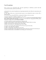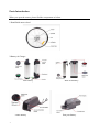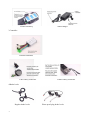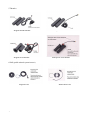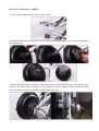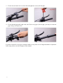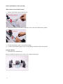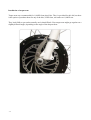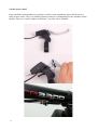
1
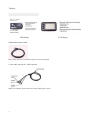
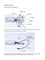
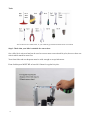
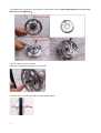
DIY Electric bike conversion kit
User Manual
1
Please read the user manual carefully before starting the conversion.
Please convert the bicycle on the basis of a full understanding of the manual.
Contents
Brief Introduction-----------------------------------------------------------3
User Precautions-------------------------------------------------------------4
Parts Introduction-----------------------------------------------------------5
Installation Steps-------------------------------------------------------------9
Final notes on installation MUST READ------------------------------24
Maintenance, warranty and spare parts-------------------------------26
2
Brief Introduction
To create an electric bicycle is a rewarding project, but caution is advised. Customers converting
their own bike are responsible for the safe operation and installation of the kit.
Please kindly read the user manual carefully before starting the conversion. We disclaim any
responsibility injury, damage or other consequences arising from the use of this product.
3
User Precautions
Even if you are an experienced rider, take the opportunity to familiarise yourself with this
conversion kits before you take your first trip.
● Read all of the enclosed installation and operating instructions and follow the instructions prior
to first use
● The e-bike kit has lots of sealed electronic parts, do not dismantle the parts, let them fall or
punctured them
● The electric parts should NEVER be submerged in liquid or left in a wet state
● Storage temperature of lithium ion battery is -20~+60 °C
● Batteries should be charged immediately after every use and never be stored for long periods of
time without maintenance charging, if you have to store them for a long period of time, please
remember to charge once at least every two months
● The bike should be checked carefully after a long time idle
● Spoke tension should be checked after the first 50km and adjusted where necessary
● Make sure the tyres have proper pressure before riding
● Make sure the brakes are operating properly before riding
● Always wear a helmet when riding an electric bicycle for your own safety
● Adhere to all valid traffic regulations
● Adhere to all national, state and local council laws
● Keep in mind that other traffic participants may underestimate the speed of an electric bicycle.
● Ride with both hands on the handlebars when riding your electric bicycle.
4
Parts Introduction
When you open the carton, please find the components as below.
1.Hand-Built motor wheel
2.Battery & Charger
Tube battery
Frame battery
5
Rear rack battery
Seat post battery
Lead acid battery
Smart charger
3.Controller
Normal controllers
Tube battery controller
Frame battery controller
4.Brake levels
Regular brake levels
6
Water-proof plug brake levels
5.Throttles
Regular thumb throttle
Waterproof thumb throttle
Regular twist throttle
Waterproof twist throttle
6.PAS (pedal assisted system/sensor)
Regular PAS
7
Removable PAS
7.Display
LED display
8.Removable motor cable
Some motor lines are not removable, please refer to packing list.
9. One cable system (4-1 cable system)
When you assemble, please notice the corresponding plug colours.
8
LCD display
Installation Guide
Controller cables introduction
-All controllers with normal cables; please refer this diagram, no matter the controller shape.
Please notice the cable colours must mirror same colours.
-All controllers with complete waterproof cables please refer this diagram, no matter what
controller shape is, please notice the cable colours must mirror same colours.
9
Tools
You are able to use similar tools, or you could buy specialized tool kits from our website
Step 1 Check that your bike is suitable for conversion:
Our e-bike kit is universal and can be used to convert most conversional bicycles, however there are
criteria which much be meet first.
Your front forks and rear dropouts must be wide enough to accept hub motor.
Front fork dropout MUST BE at least 98-102mm for regular bicycles:
10
Rear conversions require 133-137mm at least for regular bicycles:
Bromton bicycle’s front fork dropout is 80mm, please order special motors to convert Bromton
bicycles or 20” folding bicycles.
The opening on the fork or rear frame must be suitable to fit hub motor axles, too wide is not
acceptable.
★generally the diameter of motor axle is 10mm
You may have to remove a layer or 2 of paint for the axels to fit in the dropout. They’re designed to
be a very tight fit. You’re better off to remove a layer of paint to make the fit reasonable. You should
have to exert a lot of force to get the axels to go in. If you use too much force instead of filing back
a layer of paint, you risk damage to the fork and also that could result in a dropout failure due to
stress fractures.
Damage to forks is not covered by warranty.
11
Step 2:
Transfer your tyre & tube & install the motor wheel.
You will need to transfer your existing tyre and tube or a new tyre and tube to hand-built motor
wheel.
Rim tape is highly advisable. If you’re existing wheel has rim tape, simply transfer the tape across
to the new motor wheel. Otherwise, rim tape is inexpensive and available from any decent local
bike shop. That will minimize the risk of puncture.
Front motor wheel (disk OR caliper brakes):
1. Take out the original bicycle wheel and release the caliper;
12
2. dismantle the original disc and install it on the motor wheel (when tightening the screws for the
disk, fasten in diagonally);
3. Fit the spacers close to motor:
★ spacers quantities depend on your bicycle
4. Fit the spacers on the axle and insert the motor wheel;
13
5. Tighten all nuts:
6. Adjust caliper to suitable location and tighten the bolts:
14
Rear disc/V brake motor (1,000W)
1. Take out the original bicycle wheel from the bike;
2. Install the brake disc and freewheel on the motor (when tightening the screws on the disc, tighten
them diagonally):
3. Install the motor wheel and tight it. This image below on the right shows the tab washers on the
outside of the forks facing inwards. It’s also possible to turn the tabbed washers around the other
way so that they are facing OUT and located INSIDE the forks.
15
Step 3 Install display
1. Release the screws on the back of the display and fit it on the handle bar
2. Adjust the display location and tighten the screws
Step 4 Install the brake levers & throttle & handle bars
1. Take out the original brake levers and grips (left & right):
2.
16
Insert the brake lines to new electric brake levers:
3.
Fit the electric brake levers on the bike and tight the screws (left & right):
4.
Fit the throttle(generally right side) and fit the new grips (left & right; you may to warm the
grips if they are hard to fit)
If you have rapid fire, twist grip, hydraulic brakes or any other sort of integrated shifter or hydraulic
brake setup, please see the last page of this manual.
17
Step 5 Install PAS (pedal assist system/sensor)
Removable PAS, installed on the left side of the bicycle (crank arm removal not required).
1. Fit the disc on the crank axle:
2. Apply the adhesive sensor to the frame and position the pivot so that the sensor is within 1-3mm of the disk.
18
Step 6 Install battery and controller
Tube/canister/water-bottle battery
1.
Remove the bottle cage on the bicycle;
2.
Insert the bracket of tub battery, tight the screws (may look different to photo);
3.
4.
Fit the tube battery, lock it, turn off the battery
Connect all controller plugs to the corresponding terminals on the wiring loom.
Seat post battery
1. Dismantle the controller box
Please carefully keep these screws, they are a unique thread type.
19
2.
Apply the rubber o-ring around the opening hole of controller box, insert the saddle seat stem,
adjust the box location and tighten the screws;
3.
4.
Connect all cables with controller
Place the controller into the box, reassemble the box;
5.
Insert the seat post battery.
20
Step 7 Make final adjustments
Make sure the brakes are adjusted, the wheel is secure, screws are tightened and everything is
functioning as expected.
Charging
Charging plug—to connect local power
Charging port—to connect battery
1. Insert charging port on battery first, then insert charging plug to mains socket.
2. The charging signal is red during charging, it turns to green when fully charged.
The charge light will glow red whilst charging, and then green when charged.
Some charger have 2 lights. 2 lights red is charging, 1 red, 1 green means fully charged.
Load/Unload the batteries
1. Please turn the keys left/right to lock or unlock the batteries
2. The keys have two functions: to lock the battery and ignite the power (for some units, not others).
21
Installation of torque arm
Torque arms are recommended for 1,000W front wheel kits. They’re provided for this kit, but there
is the option of purchase them for any of the kits, 250W front, rear and even 1,000W rear.
They look fiddly to put on but actually aren’t that difficult. Your torque arm might go together on a
slightly different angle, depending on the angle of the dropout slots.
22
e-brake power cutoff
If the standard e-brake handles aren’t going to work for your installation, please check out our ebrake sensors online. They’re available separately and aren’t exchangeable for the standard e-brake
handles. Here are a couple of photo to illustrate 1 way they can be installed:
23
Additional points on the installation:
Motor orientation:
Different series of kits have the cable coming out on different sides. The foolproof way to orientate
the motor correctly is to make sure that the disk brake side of the motor is on the left. So when
you’re sitting on the bike, the disk brake holes should always be facing towards the left.
Spoke adjustment:
The spokes used on the e-bike hubs are very heavy duty. Because of the rigidity of the harder,
heavier gauge spokes, they may have a tendency to come loose more often than a regular bike
wheel spokes. That means that it’s a good idea to check the spoke tension after the first 50km and
then every 100km or so. If you break a spoke, we have spares available via our website.
48V bottle battery charging (specific to the 48V battery only):
Ensure that when you plug the black 4 pin battery cable plug into the base of the 48V bottle battery,
that the battery is turned off. The plug has a groove to prevent the it from going in incorrectly, but
because of the high voltage, it’s still possible for the plug to get close enough that it can ark out and
short against the wrong terminals on the base of the battery, melting the plug and doing damage to
the battery that is not covered under warranty.
Vibration:
The motor hubs can at times be under quite a lot of load which can result in mild vibrations when
accelerating or going up an incline. If there is a loose item anywhere on the bike, quite often that
can exacerbate the moderate motor vibration into an almighty drone of a vibration, giving the rider
the impression that the bike is about to come apart. If this happens to you, you have to look for
anything that could be loose. Sometimes it might be an unused disk brake bolt, or even something
loose on the rear rack of the bike. If there’s something wrong with a component on the kit (like a
motor) it won’t be that subtle.
Integrated controllers on parts lists:
When you open up the carton of a 250W bottle battery or frame battery kit, don’t despair, the
controller isn’t missing, it’s integrated into the battery.
24
Range extension
If you’re not getting the approximate quoted range out of your e-bike system, take the following
steps:
1. Pedal assist sensor
a. If you haven’t installed the pedal assist sensor, you might not get the required range
out of your kit. The pedal assist modes only work for pedal assist input, not throttle.
The throttle is awesome to use, but even moderate use of the throttle, with pedaling,
is still going to burn through the juice a lot faster than on a low-medium pedal assist
setting.
2. LED indicator lights – full charge
a. The LED and LCD battery level displays are a basic indication of battery charge, but
the only indication of a full charge, is having charged the battery and the battery
charger lights glowing green to indicate that the battery is fully charged.
3. LED indicator light – running low
a. Some customers find that the LED charge lights can lead them astray in terms of
how far the bike will go on low power. You don’t risk damaging the system by riding
all the way to the controller low voltage cutoff. Keep riding on pedal assist even after
the last LED light starts blinking
4. Hills/riding style/other factors
a. The ranges quoted are from real world testing, with some hills and some flat areas. If
your commute involves a lot of hills, that’s going to impact on the range of the kit.
1,000W kits are especially susceptible to being zapped a lot more on hills (than 250’s
anyway). If you need to purchase a second charger to charge the battery at half way,
or if you need an additional battery, they will be available for purchase online.
5. General tips
a. Make sure the wheels are running free
b. Keep the battery topped up between uses (if Li-ion)
c. Make sure the tyre pressures are at optimum
d. Pedal harder when taking off and select the right gear for assisting up hills
Trouble shooting
If you have any problems with the kit, the best way to find out what is causing the problem is to do
the following.
Disconnect all components, then connect the battery, battery cable, controller, throttle, display and
motor. In this basic installation mode you will more than likely have full function. Then go through
one by one plugging in the other components (such as the PAS or the e-brake handles) to see which
is the problem.
If there is a problem with the basic kit setup, check that the plugs are all correctly touching and that
there is a good solid connection at each junction. Check the fuses in the battery. Check the wires as
they go into the motor axel for any signs of wear or tear. If you cannot isolate the problem, you may
have to return the problem components to our factory.
25
Maintenance
We recommend to have the spoke tension of the motor wheel and the torque of all screws checked
after the first 50km.
In order to ensure extended use of the electric system, all plug-in contacts of the system should be
checked every two to three months and cleaned with a wire brush, if necessary.
Cleaning
Never use a high pressure washer or a garden hose to clean the e-bike system. The force of a
water jet could damage the electrical components of the propulsion system. Do not use water
to clean electric components. Use a wet rag or similar.
For practicality, the warranty period commences from the purchase date. All warranty details are
available online.
Visit our website for all kit information, order,
FAQ and enquiries.
Full range of accessories and replacement parts can be found on our website
26