1
Cat. No. Z263-E1-01
Smart Sensor
Wide Laser Beam CCD Measurement Sensor
ZX-GT Series
ZX-GT Series Smart Sensor
OMRON Corporation
Industrial Automation Company
Sensing Devices Division H.Q.
Application Sensors Division
Shiokoji Horikawa, Shimogyo-ku,
Kyoto, 600-8530 Japan
Tel: (81)75-344-7068/Fax: (81)75-344-7107
Regional Headquarters
OMRON EUROPE B.V.
Sensor Business Unit,
Carl-Benz-Str. 4, D-71154 Nufringen,
Germany
Tel: (49)7032-811-0/Fax: (49)7032-811-199
User's Manual
OMRON ELECTRONICS LLC
One Commerce Drive Schaumburg,
IL 60173-5302 U.S.A.
Tel: (1)847-843-7900/Fax: (1)847-843-7787
OMRON ASIA PACIFIC PTE. LTD.
No. 438A Alexandra Road # 05-05/08 (Lobby 2),
Alexandra Technopark, Singapore 119967
Tel: (65)6835-3011/Fax: (65)6835-2711
User's Manual
OMRON (CHINA) CO., LTD.
Room 2211, Bank of China Tower,
200 Yin Zhong Road,
Pu Dong New Area, Shanghai, 200120, China
Tel: (86)21-5037-2222/Fax: (86)21-5037-2200
Authorized Distributor:
Cat. No. Z263-E1-01
OMRON Corporation 2007
All Rights Reserved.
Note: Specifications subject to change without notice.
Printed in Japan.
xxxx-xxxx (xxxx) (x)
Cat. No. Z263-E1-01
Introduction
Thank you for purchasing the ZX-GT series.
This manual provides information regarding functions, performance and operating methods that
are required for using the ZX-GT.
When using the ZX-GT, be sure to observe the following:
• The ZX-GT must be operated by personnel knowledgeable in electrical engineering.
• To ensure correct use, please read this manual thoroughly to deepen your understanding of the
product.
• Please keep this manual in a safe place so that it can be referred to whenever necessary.
zx_gt.book Page 1 Wednesday, May 30, 2007 3:29 PM
APPRICATION CONSIDERATIONS
(Please read)
User's Manual
BEFORE USE
1
BASIC OPERATIONS
2
FUNCTION SETTINGS
3
COMMUNICATIONS WITH
EXTERNAL DEVICES
APPENDICES
Smart Sensor
Wide Laser Beam CCD Measurement Sensor
ZX-GT Series
4
5
zx_gt.book Page 2 Wednesday, May 30, 2007 3:29 PM
READ AND UNDERSTAND THIS DOCUMENT
Please read and understand this document before using the products. Please
consult your OMRON representative if you have any questions or comments.
WARRANTY
OMRON’s exclusive warranty is that the products are free from defects in materials
and workmanship for a period of one year (or other period if specified) from date of
sale by OMRON.
OMRON MAKES NO WARRANTY OR REPRESENTATION, EXPRESS OR
IMPLIED, REGARDING NON-INFRINGEMENT, MERCHANTABILITY, OR FITNESS
FOR PARTICULAR PURPOSE OF THE PRODUCTS. ANY BUYER OR USER
ACKNOWLEDGES THAT THE BUYER OR USER ALONE HAS DETERMINED
THAT THE PRODUCTS WILL SUITABLY MEET THE REQUIREMENTS OF THEIR
INTENDED USE. OMRON DISCLAIMS ALL OTHER WARRANTIES, EXPRESS OR
IMPLIED.
LIMITATIONS OF LIABILITY
OMRON SHALL NOT BE RESPONSIBLE FOR SPECIAL, INDIRECT, OR
CONSEQUENTIAL DAMAGES, LOSS OF PROFITS OR COMMERCIAL LOSS IN
ANY WAY CONNECTED WITH THE PRODUCTS, WHETHER SUCH CLAIM IS
BASED ON CONTRACT, WARRANTY, NEGLIGENCE, OR STRICT LIABILITY.
In no event shall responsibility of OMRON for any act exceed the individual price of
the product on which liability is asserted.
IN NO EVENT SHALL OMRON BE RESPONSIBLE FOR WARRANTY, REPAIR, OR
OTHER CLAIMS REGARDING THE PRODUCTS UNLESS OMRON’S ANALYSIS
CONFIRMS THAT THE PRODUCTS WERE PROPERLY HANDLED, STORED,
INSTALLED, AND MAINTAINED AND NOT SUBJECT TO CONTAMINATION,
ABUSE, MISUSE, OR INAPPROPRIATE MODIFICATION OR REPAIR.
2
ZX-GT User’s Manual
zx_gt.book Page 3 Wednesday, May 30, 2007 3:29 PM
SUITABILITY FOR USE
THE PRODUCTS CONTAINED IN THIS DOCUMENT ARE NOT SAFETY RATED.
THEY ARE NOT DESIGNED OR RATED FOR ENSURING SAFETY OF PERSONS,
AND SHOULD NOT BE RELIED UPON AS A SAFETY COMPONENT OR PROTECTIVE DEVICE FOR SUCH PURPOSES.
Please refer to separate catalogs for OMRON’s safety rated products.
OMRON shall not be responsible for conformity with any standards, codes, or
regulations that apply to the combination of products in the customer’s application or
use of the product.
At the customer’s request, OMRON will provide applicable third party certification
documents identifying ratings and limitations of use that apply to the products. This
information by itself is not sufficient for a complete determination of the suitability of
the products in combination with the end product, machine, system, or other
application or use.
The following are some examples of applications for which particular attention must
be given. This is not intended to be an exhaustive list of all possible uses of the
products, nor is it intended to imply that the uses listed may be suitable for the
products:
• Outdoor use, uses involving potential chemical contamination or electrical
interference, or conditions or uses not described in this document.
• Nuclear energy control systems, combustion systems, railroad systems, aviation
systems, medical equipment, amusement machines, vehicles, safety equipment,
and installations subject to separate industry or government regulations.
• Systems, machines, and equipment that could present a risk to life or property.
Please know and observe all prohibitions of use applicable to the products.
NEVER USE THE PRODUCTS FOR AN APPLICATION INVOLVING SERIOUS
RISK TO LIFE OR PROPERTY WITHOUT ENSURING THAT THE SYSTEM AS A
WHOLE HAS BEEN DESIGNED TO ADDRESS THE RISKS, AND THAT THE
OMRON PRODUCT IS PROPERLY RATED AND INSTALLED FOR THE
INTENDED USE WITHIN THE OVERALL EQUIPMENT OR SYSTEM.
ZX-GT User’s Manual
3
zx_gt.book Page 4 Wednesday, May 30, 2007 3:29 PM
PERFORMANCE DATA
Performance data given in this document is provided as a guide for the user in
determining suitability and does not constitute a warranty. It may represent the result
of OMRON’s test conditions, and the users must correlate it to actual application
requirements. Actual performance is subject to the OMRON Warranty and
Limitations of Liability.
CHANGE IN SPECIFICATIONS
Product specifications and accessories may be changed at any time based on
improvements and other reasons.
It is our practice to change model numbers when published ratings or features are
changed, or when significant construction changes are made. However, some
specifications of the product may be changed without any notice. When in doubt,
special model numbers may be assigned to fix or establish key specifications for
your application on your request. Please consult with your OMRON representative at
any time to confirm actual specifications of purchased products.
DIMENSIONS AND WEIGHTS
Dimensions and weights are nominal and are not to be used for manufacturing
purposes, even when tolerances are shown.
ERRORS AND OMISSIONS
The information in this document has been carefully checked and is believed to be
accurate; however, no responsibility is assumed for clerical, typographical, or
proofreading errors, or omissions.
PROGRAMMABLE PRODUCTS
OMRON shall not be responsible for the user’s programming of a programmable
product, or any consequence thereof.
COPYRIGHT AND COPY PERMISSION
This document shall not be copied for sales or promotions without permission.
This document is protected by copyright and is intended solely for use in conjunction
with the product. Please notify us before copying or reproducing this document in
any manner, for any other purpose. If copying or transmitting this document to
another, please copy or transmit it in its entirety.
4
ZX-GT User’s Manual
zx_gt.book Page 5 Wednesday, May 30, 2007 3:29 PM
Meanings of Signal Words
The following signal words are used in this manual.
Indicates a potentially hazardous situation which, if not avoided, will
result in minor or moderate injury, or may result in serious injury or
death. Additionally there may be significant property damage.
Indicates a potentially hazardous situation which, if not avoided,
may result in minor or moderate injury or in property damage.
Meanings of Alert Symbols
The following alert symbols are used in this manual.
Indicates general prohibitions for which there is no specific symbol.
Indicates the possibility of laser radiation.
Indicates prohibition when there is a risk of minor injury from electrical
shock or other source if the product is disassembled.
ZX-GT User’s Manual
5
zx_gt.book Page 6 Wednesday, May 30, 2007 3:29 PM
This product is not designed or rated for ensuring safety of persons.
Do not use it for such purposes.
Never look into the laser beam. Doing so continuously will result in
visual impairment.
Do not attempt to dismantle, pressurize, or incinerate the product. Doing
so may cause the laser beam to leak, resulting in the danger of visual
impairment.
6
ZX-GT User’s Manual
zx_gt.book Page 7 Wednesday, May 30, 2007 3:29 PM
Precautions for Safe Use
The following points are important to ensure safety, so make sure that they are strictly
observed.
1. Installation Environment
• Do not use the product in environments where it can be exposed to inflammable/
explosive gas.
• To secure the safety of operation and maintenance, do not install the product close to
high-voltage devices and power devices.
• Install the product in such a way that its ventilation holes are not blocked. (excluding
the connecting surface when the products are connected to each other)
• Tighten the mounting screws with a torque specified in this manual.
2. Power Supply and Wiring
• The voltage and AC power supply must be within the rated range (24 VDC +10%, -15%).
• Reverse connection of the power supply is not allowed. Connection to an AC power
supply is also not allowed.
• The output load should not be short-circuited.
• Use the power supply within the rated load.
• High-voltage lines and power lines must be wired separately from this product. Wiring
them together or placing them in the same duct may cause induction, resulting in
malfunction or damage.
• Use the product within the power supply voltage specified by this manual.
• Use a DC power supply with safety measures against high-voltage spikes (safety extra
low-voltage circuits on the secondary side).
• Use only combinations of the Sensor and Controller specified in this manual.
Controller Specifications p.133
• When connecting Controllers to each other, use only combinations of the Controllers
specified in this manual.
Connecting Controllers to each other p.37
• Connect the exclusive device (Sensor). The product might break down or malfunction
if you use a part not included in the exclusive products.
3. Other
• Do not disassemble, repair, modify, pressurize, or incinerate the product.
• Dispose of this product as industrial waste.
• Should you notice any abnormalities, immediately stop use, turn OFF the power
supply, and contact your OMRON representative.
ZX-GT User’s Manual
7
zx_gt.book Page 8 Wednesday, May 30, 2007 3:29 PM
Precautions for Correct Use
Observe the following precautions to prevent failure to operate, malfunctions, or
undesirable effects on product performance.
1. Installation Site
Do not install this product in locations subjected to the following conditions:
•
•
•
•
•
•
•
Ambient temperature outside the rating
Rapid temperature fluctuations (causing condensation)
Relative humidity outside the range of 35 to 85%
Direct vibration or shock
Reflection of intense light (such as other laser beams or electric arc-welding machines)
Direct sunlight or near heaters
Strong magnetic or electric field
Also, do not install this product in locations subjected to the following conditions due to
the degree of protection specified in the ratings:
• Presence of corrosive or flammable gases
• Presence of dust, salt, or iron particles
• Water, oil, or chemical fumes or spray
2. Power Supply and Wiring
• When using a commercially available switching regulator, make sure that the FG
terminal is grounded.
• If surge currents are present in the power lines, connect surge absorbers that suit the
operating environment.
• Before turning ON the power after the product is connected, make sure that the power
supply voltage is correct, there are no incorrect connections (e.g. load short-circuit), and
the load current is appropriate. Incorrect wiring may result in breakdown of the product.
• Before connecting/disconnecting devices, make sure that the Sensor/Controller is
turned OFF. The Sensor or Controller may break down if it is connected/disconnected
while the power is ON.
• Use the extension cable sold separately for extending the cable between the Sensor
(receiver) and the Controller.
p.20
3. Warming Up
After turning the power supply ON, allow the product to stand for at least 10 minutes
before use. The circuits are still unstable just after the power supply is turned ON, so
measurement values may fluctuate gradually.
4. Maintenance and Inspection
Do not use thinner, benzene, acetone or kerosene to clean the Sensor and Controller. If
large dust particles adhere to the filter on the front of the Sensor, use a blower brush
(used to clean camera lenses) to blow them off. Do not use breath from your mouth to
blow the dust off. To remove dust particles from the Sensor, wipe gently with a soft cloth
(for cleaning lenses) moistened with a small amount of alcohol. Do not use excessive
force to wipe off dust particles. Scratches to the filter might cause error.
8
ZX-GT User’s Manual
zx_gt.book Page 9 Wednesday, May 30, 2007 3:29 PM
Editor’s Note
■ Meaning of Symbols
Menu items that are displayed on the Controller’s LCD screen, and windows, dialog boxes
and other GUI elements displayed on the PC are indicated enclosed by brackets “[ ]”.
■ Visual Aids
Important
Note
Indicates points that are important to achieve the full product performance,
such as operational precautions.
Indicates application procedures.
Indicates pages where related information can be found.
ZX-GT User’s Manual
9
zx_gt.book Page 10 Wednesday, May 30, 2007 3:29 PM
MEMO
10
ZX-GT User’s Manual
zx_gt.book Page 11 Wednesday, May 30, 2007 3:29 PM
CONTENTS
Operation Step Guide . . . . . . . . . . . . . . . . . . . . . . . . . 16
1.BEFORE USE
ZX-GT Series . . . . . . . . . . . . . . . . . . . . . . . . . . . . . . . . 20
System Configuration . . . . . . . . . . . . . . . . . . . . . . . . . . . . . 20
Part Names and Functions . . . . . . . . . . . . . . . . . . . . . . . . . 21
Mounting and Connecting Devices . . . . . . . . . . . . . . 25
Mounting the Controller . . . . . . . . . . . . . . . . . . . . . . . . . . . 27
1
Mounting the Sensor . . . . . . . . . . . . . . . . . . . . . . . . . . . . . 25
CONTENTS
Connecting Devices . . . . . . . . . . . . . . . . . . . . . . . . . . . . . . 28
Connecting Controllers to Each Other . . . . . . . . . . . . . . . . 37
Connecting Interface Units . . . . . . . . . . . . . . . . . . . . . . . . . 38
Initializing Controller Settings . . . . . . . . . . . . . . . . . . 39
2.BASIC OPERATIONS
Setting Measurement Conditions - FUN Mode . . . . . 42
Adjusting the Optical Axis and Registering the Standard
Received Light Intensity . . . . . . . . . . . . . . . . . . . . . . . . . . . 42
Selecting the Measurement Mode . . . . . . . . . . . . . . . . . . . 44
Setting Thresholds - T Mode . . . . . . . . . . . . . . . . . . . 45
Functions and Operations during Operation
- RUN Mode . . . . . . . . . . . . . . . . . . . . . . . . . . . . . . . . . 46
Switching the Measured Value Display . . . . . . . . . . . . . . . 46
Executing and Canceling a Zero Reset . . . . . . . . . . . . . . . 47
ZX-GT User’s Manual
11
zx_gt.book Page 12 Wednesday, May 30, 2007 3:29 PM
3.FUNCTION SETTINGS
Settings Matched to Specific Measurement
Requirements . . . . . . . . . . . . . . . . . . . . . . . . . . . . . . . . 50
Specific Measurement Requirement and Measurement
Mode Used . . . . . . . . . . . . . . . . . . . . . . . . . . . . . . . . . . . . . 50
Explanation of Measurement Modes . . . . . . . . . . . . . . . . . 52
Adjusting Detection Conditions . . . . . . . . . . . . . . . . . 61
Measurement Cycle . . . . . . . . . . . . . . . . . . . . . . . . . . . . . . 61
Number of Samples to Average . . . . . . . . . . . . . . . . . . . . . 62
Binary Level . . . . . . . . . . . . . . . . . . . . . . . . . . . . . . . . . . . . 63
Edge Filter . . . . . . . . . . . . . . . . . . . . . . . . . . . . . . . . . . . . . 64
Setting Output Conditions . . . . . . . . . . . . . . . . . . . . . 65
Judgment output timing (timer) . . . . . . . . . . . . . . . . . . . . . . 65
Hysteresis . . . . . . . . . . . . . . . . . . . . . . . . . . . . . . . . . . . . . . 67
Analog Output Conditions . . . . . . . . . . . . . . . . . . . . . . . . . . 68
Setting Hold Functions . . . . . . . . . . . . . . . . . . . . . . . . 73
Hold . . . . . . . . . . . . . . . . . . . . . . . . . . . . . . . . . . . . . . . . . . 73
Delay Hold . . . . . . . . . . . . . . . . . . . . . . . . . . . . . . . . . . . . . 75
Changing Display Conditions . . . . . . . . . . . . . . . . . . . 77
Reversing the Display . . . . . . . . . . . . . . . . . . . . . . . . . . . . . 77
Changing the Number of Display Digits . . . . . . . . . . . . . . . 78
Adjusting the Display Brightness (ECO mode) . . . . . . . . . . 79
Setting Communication Conditions . . . . . . . . . . . . . . 80
RS-232C Communications Specifications . . . . . . . . . . . . . 80
Setting the Binary Output Cycle . . . . . . . . . . . . . . . . . . . . . 81
Special Functions . . . . . . . . . . . . . . . . . . . . . . . . . . . . 82
Zero Reset Memory . . . . . . . . . . . . . . . . . . . . . . . . . . . . . . 82
Display during a Zero Reset . . . . . . . . . . . . . . . . . . . . . . . . 83
Key Lock . . . . . . . . . . . . . . . . . . . . . . . . . . . . . . . . . . . . . . . 84
Switching Banks . . . . . . . . . . . . . . . . . . . . . . . . . . . . . . . . . 85
Displaying the System Version . . . . . . . . . . . . . . . . . . . . . . 87
12
ZX-GT User’s Manual
zx_gt.book Page 13 Wednesday, May 30, 2007 3:29 PM
4.COMMUNICATIONS WITH EXTERNAL
DEVICES
Output Data List . . . . . . . . . . . . . . . . . . . . . . . . . . . . . . 90
Communications Using the Controller I/O Cable . . . 91
Using the Controller I/O Cable . . . . . . . . . . . . . . . . . . . . . . 91
Binary Output . . . . . . . . . . . . . . . . . . . . . . . . . . . . . . . . 93
Assignments and Functions of Output Signal Wires . . . . . 93
Output Format . . . . . . . . . . . . . . . . . . . . . . . . . . . . . . . . . . 94
I/O Timing Charts . . . . . . . . . . . . . . . . . . . . . . . . . . . . . 95
RS-232C . . . . . . . . . . . . . . . . . . . . . . . . . . . . . . . . . . . 100
Communications on the RS-232C Interface . . . . . . . . . . . 100
Connecting External Devices . . . . . . . . . . . . . . . . . . . . . . 101
About Communications Commands . . . . . . . . . . . . . . . . . 102
Setting Acquisition/Change Commands . . . . . . . . . . . . . . 107
CONTENTS
Measurement Control/Measured Value Acquisition
Commands . . . . . . . . . . . . . . . . . . . . . . . . . . . . . . . . . . . . 123
Bank Control Command . . . . . . . . . . . . . . . . . . . . . . . . . . 127
Utility Command . . . . . . . . . . . . . . . . . . . . . . . . . . . . . . . . 128
5.APPENDICES
Specifications and External Dimensions . . . . . . . . 130
Sensor . . . . . . . . . . . . . . . . . . . . . . . . . . . . . . . . . . . . . . . 130
Controller . . . . . . . . . . . . . . . . . . . . . . . . . . . . . . . . . . . . . 133
Calculating Unit . . . . . . . . . . . . . . . . . . . . . . . . . . . . . . . . 135
Interface Unit . . . . . . . . . . . . . . . . . . . . . . . . . . . . . . . . . . 136
Extension Cable . . . . . . . . . . . . . . . . . . . . . . . . . . . . . . . . 138
Error Messages and Corrective Actions . . . . . . . . . 140
Setup Errors
. . . . . . . . . . . . . . . . . . . . . . . . . . . . . . . . . . 140
Measurement Errors . . . . . . . . . . . . . . . . . . . . . . . . . . . . 140
Standard Received Light Intensity Registration Errors . . . 141
Default Values . . . . . . . . . . . . . . . . . . . . . . . . . . . . . . 142
Basic Knowledge for Operation . . . . . . . . . . . . . . . . 143
ZX-GT User’s Manual
13
zx_gt.book Page 14 Wednesday, May 30, 2007 3:29 PM
Reading Displays . . . . . . . . . . . . . . . . . . . . . . . . . . . . . . . 143
List of Key Operations . . . . . . . . . . . . . . . . . . . . . . . . . . . 143
Laser Safety . . . . . . . . . . . . . . . . . . . . . . . . . . . . . . . . 144
Label Replacement . . . . . . . . . . . . . . . . . . . . . . . . . . . . . . 144
Requirements from Regulations and
Standards . . . . . . . . . . . . . . . . . . . . . . . . . . . . . . . . . . 146
Summary of Requirements to Manufactures . . . . . . . . . . 146
Summary of Requirements to User . . . . . . . . . . . . . . . . . 150
Definitions of Laser Classification . . . . . . . . . . . . . . . . . . . 153
Compliance with EC Directives . . . . . . . . . . . . . . . . 154
Quick Reference for Displays . . . . . . . . . . . . . . . . . . 156
INDEX . . . . . . . . . . . . . . . . . . . . . . . . . . . . . . . . . . . . . 161
Revision History . . . . . . . . . . . . . . . . . . . . . . . . . . . . 164
14
ZX-GT User’s Manual
zx_gt.book Page 15 Wednesday, May 30, 2007 3:29 PM
MEMO
CONTENTS
ZX-GT User’s Manual
15
zx_gt.book Page 16 Wednesday, May 30, 2007 3:29 PM
Operation Step Guide
Basic Operation Procedure
Mounting and Connections
Mounting the Sensor
p.25
Mounting the Controller
p.27
Connecting Devices
p.28
Preparations for Measurement (FUN)
Adjusting the Optical Axis and Registering the
Standard Received Light Intensity
Selecting the Measurement Mode
Setting Thresholds (T)
p.42
p.44
p.45
Start of Operation (RUN)
Zero Reset
p.47
Communications with External Devices
16
I/O Cable
p.91
Binary Output
p.93
RS-232C
p.100
Operation Step Guide
ZX-GT User’s Manual
zx_gt.book Page 17 Wednesday, May 30, 2007 3:29 PM
To Improve Controller Performance
Ignoring Rapid Changes in Measured Values
Adjusting the Number of Samples to Average
p.62
Adjusting the Detection Sensitivity
Adjusting the Binary Level
p.63
Adjusting the Edge Filter
p.64
Stabilizing Judgment Output
Changing/Adjusting the Timing of Judgment Outputs
p.65
Changing the Output Time
p.65
Adjusting Hysteresis
p.67
Setting the Delay Time
p.75
Returning Controller Settings to Their Defaults
p.39
Speeding the Measurement Cycle Up
p.61
Setting Hold Functions
p.73
Reversing the Controller Display
p.77
Changing the Number of Controller Display Digits
p.78
Operating in the ECO (power-saving) Mode
p.79
Holding the Zero Reset Value
p.82
Offsetting the Zero Reset Value
p.83
Key Lock Function
p.84
Switching Banks
p.85
(If required)
ZX-GT User’s Manual
Operation Step Guide
17
zx_gt.book Page 18 Wednesday, May 30, 2007 3:29 PM
MEMO
18
Operation Step Guide
ZX-GT User’s Manual
zx_gt.book Page 19 Wednesday, May 30, 2007 3:29 PM
BEFORE USE
1
BEFORE USE
ZX-GT Series
20
System Configuration
Part Names and Functions
20
21
Mounting and Connecting Devices
25
Mounting the Sensor
Mounting the Controller
Connecting Devices
Connecting Controllers to Each Other
Connecting Interface Units
25
27
28
37
38
Initializing Controller Settings
39
zx_gt.book Page 20 Wednesday, May 30, 2007 3:29 PM
ZX-GT Series
The ZX-GT Series Smart Sensors are a length measurement sensor using a CCD device.
Position, dimensions, and other information can be stably measured by a line beam
comprising a visible semiconductor laser and an optical scale on the CCD line sensor.
System Configuration
Sensor
ZX-GT28___
Controller
Analog outputs/judgment outputs
PLC
ZX-GTC__
Control input
Measured values and judgments can be
output. Also, the Controller can be controlled
(e.g. switching of measurement conditions
and input of triggers).
Interface
Unit
ZX-GIF__
Binary output
Commands can be used to input triggers
and acquire measurement results. Also, the
Controller can be controlled from a PC (e.g.
changing of setup data).
SmartMonitor GT
ZX-GSW11
Exclusive PC software
allows complex setups and
verification of measured
values to be performed
with ease.
PC
RS-232C
Options
• Receiver-Controller Extension Cable
p.29
Extension cable:
1 m, 2 m, 5 m, 8 m, 20 m
ZX-XGC__A (standard cable)
ZX-XGC__R (flexible cable)
• Calculating Unit
ZX-CAL2
• Connecting Controllers to Each Other p.37
• Calculation of measurement results p.59
20
ZX-GT Series
ZX-GT User’s Manual
zx_gt.book Page 21 Wednesday, May 30, 2007 3:29 PM
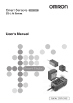
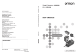
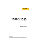
Part Names and Functions
Sensor
(5)
Emitter
Receiver
(3)
(1)
1
BEFORE USE
(2)
(4)
Name
Function
(1) Laser indicators
These are laser beam warning indicators. When the laser is being
emitted, the "laser ON indicator (ON, green)" turns ON, and when
the laser has deteriorated, the "laser deterioration alarm indicator
(ALARM, red)" turns ON.
Laser ON indicator
Laser deterioration alarm indicator
(2) Laser emitter
This emits the laser for measurement.
(3) Laser receiver
This receives the laser light emitted from the laser emitter.
(4) Connector
This is the connector for connecting to the Controller.
(5) Optical axis setting
indicator
This indicator turns ON when the laser's optical axis is aligned in
the optical axis adjustment mode.
Optical axis mode p.42
ZX-GT User’s Manual
ZX-GT Series
21
zx_gt.book Page 22 Wednesday, May 30, 2007 3:29 PM
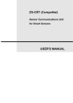
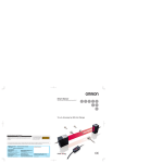
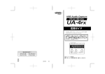
Controller
Connector
Display and Operation Panel
(1)
(2)
(3)
(4)
(9)
(1)
(4)
(3)
(2)
Ventilation holes
(5)
(6)
(7)
(8)
Connectors
Name
Function
(1) Input cable
This is for connecting the Sensor receiver.
(2) Voltage/Current
This switch is for selecting voltage output or current output as the
switch (on rear side) analog output.
(default value: voltage output)
Voltage/Current switch
Voltage output
Current output
Output scaling settings are also required when switching the output.
p.68
Important
Before operating this switch, make sure that the Controller is turned
OFF. Make sure that the load connected to "analog output wire (coaxial) - analog GND wire" satisfies the rating of the set state
(voltage or current output) before turning the Controller ON.
Otherwise, the Controller may be damaged.
Rating of Connected Loads (I/O Circuit Diagrams) p.33
(3) Controller connector This connector is for connecting Calculating and Interface Units.
(total 2 connectors, one on each side)
(4) Output cable
22
ZX-GT Series
The output cable connects the Controller to the power supply and
external devices, such as timing sensors or PLCs.
ZX-GT User’s Manual
zx_gt.book Page 23 Wednesday, May 30, 2007 3:29 PM
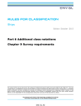
Display and operation panel
Function
(1) Bank 1 indicator
This indicator turns ON when bank 1 is selected.
(2) Bank 2 indicator
This indicator turns ON when bank 2 is selected.
(3) Zero reset
indicator
This indicator turns ON when the zero reset function is enabled.
(4) Judgment output
indicator
HIGH LED : This indicator lights when "the HIGH threshold <
1
Name
BEFORE USE
the measured value."
PASS LED : This indicator lights when "the LOW threshold ≤
the measured value ≤ the HIGH threshold."
LOW LED
: This indicator lights when "the measured value <
the LOW threshold value."
(5) Main display
indicator
The main display shows measured values and function names.
(6) Sub-display
indicator
The sub-display shows additional information and function settings
for measurements.
Reading Displays p.143
Reading Displays p.143
(7) Threshold
switch
The threshold switch selects whether to set (or display) the HIGH
or LOW threshold.
(8) Mode
switch
The mode switch selects the operation mode.
FUN : Select this mode when setting measurement conditions.
T
: Select this mode when setting thresholds.
RUN : Select this mode when performing measurement.
(9) Control keys
Use the Control Keys to set the measurement conditions and
switch the display.
List of Key Operations p.143
ZX-GT User’s Manual
ZX-GT Series
23
zx_gt.book Page 24 Wednesday, May 30, 2007 3:29 PM
Interface Unit
Connector
Display
(3)
(1)
(2)
(2)
(1)
(4)
(3)
(4)
Connector
Name
Function
(1) RS-232C connector The RS-232C connector is for connecting the Controller to external
devices, such as a PC or a PLC.
(2) Controller connector This connector is for connecting the ZX-GTC Controllers.
(3) Binary output cable
This cable connects external devices such as a PLC so that
measurement data is output in binary.
(4) Rear switch
This switch is not used during measurement. Be sure to leave this
switch at its default setting (position in figure below). If this switch
setting is changed, the communications functions will be changed
and the Controller will not operate correctly.
Display
Name
Function
(1) Power ON indicator The power ON indicator lights while the power is ON.
(2) Controller
communications
indicator
BUSY: This indicator lights when communications commands are
being issued to the Controller.
ERR : This indicator lights if an error occurs during
communications with the Controller.
(3) Binary output indicator This indicator lights during binary output.
(4) RS-232C
communications
indicator
24
ZX-GT Series
BUSY: This indicator lights when RS-232C communications is in
progress.
ERR : This indicator lights if an error occurs during RS-232C
communications.
ZX-GT User’s Manual
zx_gt.book Page 25 Wednesday, May 30, 2007 3:29 PM
Mounting and Connecting Devices
Mounting the Sensor
1
Never look into the laser beam. Doing so continuously will result in
visual impairment.
BEFORE USE
Do not attempt to dismantle, pressurize, or incinerate the product. Doing
so may cause the laser beam to leak, resulting in the danger of visual
impairment.
Important
If a measurement target has a shiny surface, reflected light might adversely influence adjacent
Sensors. Mount the Sensor so that it is not influenced by reflected light.
Example: XY cross measurement
Place the Sensors so that their optical axes do not overlap each other.
X
ZX-GT User’s Manual
Y
Mounting and Connecting Devices
25
zx_gt.book Page 26 Wednesday, May 30, 2007 3:29 PM
Separate Type (Emitter and Receiver)
Fix the Sensor onto the mounting base with
M4 screws.
0 to 500 (mm)
Tightening torque: 1.2 N•m
Important
For details on the positions of screw holes, check
the external dimensions in "5 APPENDICES."
• External dimensions p.131
• Adjusting the Optical Axis p.42
Integrated Type
Fix the Sensor onto the mounting base with
M3 screws.
Tightening torque: 0.5 N•m
Important
For details on the positions of screw holes, check
the external dimensions in "5 APPENDICES."
External dimensions p.132
26
Mounting and Connecting Devices
ZX-GT User’s Manual
zx_gt.book Page 27 Wednesday, May 30, 2007 3:29 PM
Mounting the Controller
1
Hook the connector end of the
Controller onto the DIN track.
Important
2
2
BEFORE USE
1
1
Always hook the connector end of the
Controller onto the DIN track first. Mounting
strength may decrease if the I/O cable end
is hooked onto the DIN track first.
Push the Controller down onto
the DIN track until the hook on the
I/O cable side is locked.
Important
After mounting the Controller on the DIN
track, attach the end plates (sold
separately) on both sides of the Controller.
DIN track (sold separately)
PFP-100N (1 m)
PFP-50N (0.5 m)
PFP-100N2 (1 m)
End plate
Removal
1
Push the Controller up towards
the connector side.
2
2
Lift up the Controller from the
connector end, and remove it
from the DIN track.
1
ZX-GT User’s Manual
Mounting and Connecting Devices
27
zx_gt.book Page 28 Wednesday, May 30, 2007 3:29 PM
Connecting Devices
Connecting Devices in the Basic Configuration
Important
Before connecting/disconnecting the Sensor, make
sure that the Controller is turned OFF. The
Controller may break down if the Sensor is
connected or disconnected while the power is ON.
1
Insert the receiver connector into
the Controller connector.
1
2
Connect the Controller and
Sensor sync wires.
Controller sync output wire : yellow
Emitter sync input wire
: red
Important
2
3
3
The Controller's default mode is the
standard mode. Measurement is not
possible without the sync wires connected.
3
Connect the power wire (brown)
and the GND wire (blue) of the
emitter and the Controller I/O cable.
Note
The following power supply
recommended:
• S8VS-03024 (24 VDC, 1.3 A)
is
Note
When the measurement cycle has been changed to the high-speed mode (FAST), wiring of
the sync wires is not required. Note, however, that the Controller becomes more susceptible
to the influence of ambient light in this case.
Important
Do not mount the Controller in such a way that a load is steadily applied on the connector, for
example, with tension applied to the cables.
28
Mounting and Connecting Devices
ZX-GT User’s Manual
zx_gt.book Page 29 Wednesday, May 30, 2007 3:29 PM
To extend the connection between the receiver and the Controller
The cable connection between the receiver and the Controller can be extended by up to
30 meters using the extension cable (sold separately). The emitter side can be extended
by up to 30 meters by connecting via the terminal block, for example.
Within 30 m
Connect via terminal block
Other than
sync wire
*1:
Sync wire
Cable
0.2 m
Cable
2m
Connect via terminal block
Within 26 m
(The sync wire can be extended by up to 30 meters between
the emitter and the Controller.)
BEFORE USE
Cable
2m
1
Within
30 m
Extension cable(*1)
: 1 m, 2 m, 5 m, 8 m, 20 m
ZX-XGC__A (standard cable)
ZX-XGC__R (flexible cable)
Cable
2m
Within
10 m
Other than
sync wire
Up to two extension cables can be connected. However, be sure to limit the total extension cable length
between the receiver and the Controller to 30 meters (including the receiver cable).
Wiring the Sensor (emitter)
Wiring diagram
Brown
Blue
Orange
Red
Power supply (24 VDC)
GND (0 V)
Laser deterioration alarm output
Laser OFF input/sync input
Names and functions
Cable color Name
Brown
Blue
Orange
Red
Function
Power supply
(24 VDC)
This is the power supply terminal. Connect the 24 VDC power
supply to this terminal.
When using a PNP type Controller, the power supply terminal is
also the common terminal for all I/O.
GND (0V)
This is the power supply 0 V terminal.
When using an NPN type Controller, the power supply terminal is
also the common terminal for all I/O.
Laser deterioration This output turns ON when the semiconductor laser deteriorates.
alarm output
Replace the Sensor when this output turns ON.
Laser emission stops when this output turns ON.
Laser OFF
Synchronized operation is available with this wire connected to the
input/sync
Controller's sync output, and the influence of ambient light can be reduced.
input
Laser output can also be turned OFF with this input short-circuited to 0
V (24 V in the case of a PNP type Controller) in this connection state.
ZX-GT User’s Manual
Mounting and Connecting Devices
29
zx_gt.book Page 30 Wednesday, May 30, 2007 3:29 PM
Wiring the Controller
Wiring diagram
Brown
Blue
White
Green
Gray
Co-axial (black)
Co-axial (shield)
Pink
Orange
Purple
Red
Yellow
Light blue
Black
Power supply (24 V)
GND (0 V)
HIGH
PASS
4 output
terminals
LOW
Analog output
Analog GND
Bank switching input
Zero reset input
Timing input
4 input
terminals
Reset input
Sync output
Unused
Unused
Important
• Use a stabilized power supply separate from other devices and power systems for the
Controller, particularly when high resolution is required.
Recommended power supply p.28
• Wire the Controller correctly. Otherwise, the Controller may be damaged. (Pay particular
attention to prevent contact between the analog output and other wires.)
• Use the blue wire (GND (0 V)) for the power supply, and the shielded wire sheath (analog
GND) together with the black wire (analog output) for analog output. Connect analog GND to
GND (0 V) even when analog output is not used.
Names and Functions
Cable color Name
Function
Brown
Power supply
(24 V)
This is the power supply terminal. Connect the 24 VDC power supply to
this terminal. When using a PNP type Controller, the power supply
terminal is also the common terminal for all I/O excluding analog output.
Blue
GND (0 V)
This is the power supply 0 V terminal. When using an NPN type Controller,
this terminal is also the common terminal for all I/O excluding analog output.
Co-axial Analog GND
(shield)
Connect this cable to the input device as the GND for analog output.
Yellow
Normally, wire this cable directly to the sync input wire and run the
Controller in the standard mode (NORM). When the Controller is run in
the high-speed mode (FAST), operation is possible without wiring this
cable. (Note that, in the high-speed mode, the Controller becomes more
susceptible to the influence of ambient light than in the standard mode.)
Sync output
Assignments and Functions of I/O Signal Wires p.91
30
Mounting and Connecting Devices
ZX-GT User’s Manual
zx_gt.book Page 31 Wednesday, May 30, 2007 3:29 PM
Wiring the Interface Unit Output Cables
Light blue
Red/white
Black
Yellow
Brown
Pink
Green
White
Orange
Red
Purple
Bright green
D10
D9
D8
D7
D6
Binary output
BEFORE USE
Gray
D11
1
Blue
GATE
D5
D4
D3
D2
D1
D0
Unused
Assignments and Functions of Output Signal Wires p.93
ZX-GT User’s Manual
Mounting and Connecting Devices
31
zx_gt.book Page 32 Wednesday, May 30, 2007 3:29 PM
Sensor (emitter) I/O Circuit Diagrams
NPN type Controller (ZX-GT28E11)
Brown
24 VDC
Internal circuit
Load
Laser deterioration
Orange alarm output
24 VDC
Blue
GND (0 V)
Red
Laser OFF input/
sync input
Shielded
Shield not connected internally
PNP type Controller (ZX-GT28E41)
Internal circuit
Brown
24 VDC
Laser deterioration
Orange alarm output
Load
Blue
GND (0 V)
Red
Laser OFF input/
sync input
24 VDC
Shield
Shield not connected internally
32
Mounting and Connecting Devices
ZX-GT User’s Manual
zx_gt.book Page 33 Wednesday, May 30, 2007 3:29 PM
Controller I/O Circuit Diagrams
Important
Make sure that the load connected to "analog output wire (co-axial) - analog GND wire"
satisfies the rating of the set state (voltage or current output) before turning the Controller ON.
Otherwise, the Controller may be damaged.
1
NPN type Controller (ZX-GTC11)
BEFORE USE
Brown 24 VDC
Load Load Load
HIGH
White judgment output
Green PASS judgment output
Gray
LOW judgment output
Internal circuit
24 VDC
Blue
GND (0 V)
Pink
Bank switching input
Purple Timing input
Orange Zero reset input
Red
Reset input
Current output
4 to 20 mA
Voltage/Current
switch
Co-axial (black) Analog output
Voltage output
±4 V
Output resistance
100 Ω
Load
Co-axial (shield) Analog GND
Yellow
Current output: 300 Ω or less
Voltage output: 10 kΩ or more
Sync output
Light blue Unused
Black
ZX-GT User’s Manual
Unused
Mounting and Connecting Devices
33
zx_gt.book Page 34 Wednesday, May 30, 2007 3:29 PM
PNP type Controller (ZX-GTC41)
Brown 24 VDC
White HIGH judgment output
Green PASS judgment output
Gray
LOW judgment output
Internal circuit
Load Load Load
Blue
GND (0 V)
Pink
Bank switching input
24
VDC
Purple Timing input
Orange Zero reset input
Red
Reset input
Current output
4 to 20 mA
Voltage/Current
switch
Co-axial (black) Analog output
Voltage output
±4 V
Output resistance
Co-axial (shield) Analog GND
100 Ω
Yellow
Load Current output: 300 Ω or less
Voltage output: 10 kΩ or more
Sync output
Light blue Unused
Black
34
Mounting and Connecting Devices
Unused
ZX-GT User’s Manual
zx_gt.book Page 35 Wednesday, May 30, 2007 3:29 PM
Interface Unit I/O Circuit Diagrams
The following circuit configurations are used for data outputs (D0 to D11) and the total of
13 GATE signal outputs.
NPN type
1
Bright green Unused
BEFORE USE
Light blue GATE
Red/white D11
Black
D10
Yellow D9
Brown D8
Internal circuit
Same as D0 circuit
Blue
D7
Pink
D6
Gray
D5
Same as D0 circuit
Green D4
White D3
Orange D2
Red
D1
Purple D0
Controller
ZX-GT User’s Manual
Load
Blue GND (0)
Brown 12 to 24 VDC
Mounting and Connecting Devices
35
zx_gt.book Page 36 Wednesday, May 30, 2007 3:29 PM
PNP type
Controller
Brown 12 to 24 VDC
Blue
GND (0 V)
Load
Red/white D11
Black D10
Internal circuit
Yellow D9
Brown D8
Same as D0 circuit
Blue
D7
Pink
D6
Gray
D5
Green D4
Same as D0 circuit
White D3
Orange D2
Red
D1
Purple D0
Light blue GATE
Bright green Unused
36
Mounting and Connecting Devices
ZX-GT User’s Manual
zx_gt.book Page 37 Wednesday, May 30, 2007 3:29 PM
Connecting Controllers to Each Other
Controllers are connected to each other via a Calculating Unit.
BEFORE USE
1
2
1
The number of Controllers that can be connected to each other is as follows:
• When calculating Controller measured values: three Controllers
Calculation can be performed on two of these
Controllers. (One of the calculation targets
must always be CH1.)
• When multiple points are measured and are collectively output from the Interface Unit:
three Controllers or less
Open the Controller connector
cover by lifting and sliding it up.
2
Mount the Calculating Unit on a
DIN track.
3 4
1
1
3
Slide the Calculating Unit
and insert it into the connector on
the Controller.
4
Slide the Controller to insert it
into the connector
Calculating Unit.
on
the
Important
• Provide power to all connected Controllers.
• Connect the emitter sync wires to the respective Controllers.
• Wiring the Sensor (emitter) p.29
• Wiring the Controller p.30
ZX-GT User’s Manual
Mounting and Connecting Devices
37
zx_gt.book Page 38 Wednesday, May 30, 2007 3:29 PM
Connecting Interface Units
When outputting measurement data in binary or performing RS-232C communications,
attach the Interface Unit (sold separately).
1
2
Open the Controller connector
cover by lifting and sliding it up.
2
Mount the Interface Unit on a DIN
track.
3
Note
1
3
Slide the Interface Unit to insert it
into the connector
Controller.
on
the
Channels Nos. when Controllers are connected to each other
The channel Nos. when Controllers are connected to each other are arranged as follows from
the right "CH1, CH2, CH3".
Interface
Unit
Controller
CH3
Note
CH2
CH1
Cable clamp provided with the Controller
The RS-232C cable can be fixed to devices, for example, using the cable clamp supplied with
the Controller.
Installation
Removal
Lift up the tab.
38
Mounting and Connecting Devices
ZX-GT User’s Manual
zx_gt.book Page 39 Wednesday, May 30, 2007 3:29 PM
Initializing Controller Settings
Important
The settings of all banks and system settings are initialized regardless of the currently selected
bank No. To save these settings, back them up to a personal computer using the SmartMonitor
GT (ZX-GSW11) before performing initialization.
BEFORE USE
1
1
Default States p.142
Initialize Controller settings.
Select [INIT].
Hold down to confirm the selection.
During initialization of the Controller settings,
"-----" is displayed one digit at a time.
SUB
When initialization is completed, [OK] is displayed.
SUB
ZX-GT User’s Manual
Initializing Controller Settings
39
zx_gt.book Page 40 Wednesday, May 30, 2007 3:29 PM
MEMO
40
Initializing Controller Settings
ZX-GT User’s Manual
zx_gt.book Page 41 Wednesday, May 30, 2007 3:29 PM
BASIC OPERATIONS
2
Adjusting the Optical Axis and Registering the
Standard Received Light Intensity
Selecting the Measurement Mode
42
44
Setting Thresholds - T Mode
45
Functions and Operations during Operation 46
RUN Mode
Switching the Measured Value Display
Executing and Canceling a Zero Reset
46
47
BASIC OPERATIONS
S e t t i ng Me a s u r e m e nt C on di t i on s F U N Mo d e
42
zx_gt.book Page 42 Wednesday, May 30, 2007 3:29 PM
Setting Measurement Conditions - FUN Mode
Adjusting the Optical Axis and Registering
the Standard Received Light Intensity
When using an integrated Sensor, adjustment of the optical axis in step 3 is not required.
Important
Connect the Controller and Sensor sync wires.
• Wiring the Sensor (emitter) p.29
• Wiring the Controller p.30
1
Switch to the optical axis adjustment mode.
Select [ALIGN].
SUB
2
Switch to the received light balance display to
show received light balance and light
intensity.
Confirm the selection.
3
Adjust the emitter while verifying the light intensity.
• Adjusting the received light intensity while
viewing the receiver
Move the emitter in the four directions (left, right,
top and bottom) to adjust the received light
intensity until the optical axis setting indicator
(green) on the receiver lights.
42
SUB
Setting Measurement Conditions - FUN Mode
Emitter
Receiver
Optical axis
setting indicator
ZX-GT User’s Manual
zx_gt.book Page 43 Wednesday, May 30, 2007 3:29 PM
(1) Received light intensity
The received light intensity is displayed as a
numerical value.
Standard mode (NORM): about 70 or more
High-speed mode (FAST):about 100 or more
Move the emitter to the left and right to adjust
the received light intensity until the display
indicates the above values.
SUB
• Adjusting the received light intensity while
viewing the Controller
Received light balance
Received light intensity
(2) Received light balance
The received light balance of the CCD is displayed.
2
• When one of the sides of the display is missing
BASIC OPERATIONS
Move the emitter in the direction in which the
display is missing to adjust.
• When both sides of the display are missing
• Insufficient received light intensity?
Move the emitter to the left and right to increase
the received light intensity.
• Sync output wired?
Wire the Controller sync output and Sensor
sync input.
• When the center of the display is missing
• Insufficient received light intensity?
Move the emitter to the left and right to increase
the received light intensity.
• Dirty emitter surface or object blocking light path?
Clean the emitter surface or remove object
blocking light path.
Note
The received light waveform can be observed in more detail on the exclusive PC
software (SmartMonitor GT (ZX-GSW11)).
4
Register the standard received light intensity.
Hold down for at least three seconds.
When registration of the standard received light intensity ends normally, [OK] is
displayed on the sub-display after "-----".
When registration of the standard received light intensity fails, an error is displayed.
Standard Received Light Intensity Registration Errors p.141
ZX-GT User’s Manual
Setting Measurement Conditions - FUN Mode
43
zx_gt.book Page 44 Wednesday, May 30, 2007 3:29 PM
Selecting the Measurement Mode
Select the measurement mode matched to your specific measurement requirements from
the FUN mode menu.
Specific Measurement Requirement and Measurement Mode Used p.50
The following describes, as an example, the basic operation procedure for measuring the
outer diameter.
1
Select the measurement mode.
Select [MODE].
Select [DIA].
SUB
Confirm the selection.
44
Setting Measurement Conditions - FUN Mode
ZX-GT User’s Manual
zx_gt.book Page 45 Wednesday, May 30, 2007 3:29 PM
Setting Thresholds - T Mode
In this mode, set the measured values for a PASS (OK) judgment. Both HIGH and LOW
threshold values are set. Three judgment results are output; "HIGH", "PASS" and "LOW".
HIGH threshold
Measured value
LOW threshold
HIGH
(ON when measured value > HIGH threshold)
(ON when LOW threshold ≤ measured value
≤ HIGH threshold)
ON
PASS OFF
ON
OFF
BASIC OPERATIONS
LOW
2
Output
ON
OFF
(ON when measured value < LOW threshold)
Note
In the special mode (IC lead pitch or IC lead width judgment mode), the following values are
output:
HIGH:Standard value setting
LOW: Tolerance setting
Measurement Cycle p.61
The following describes, as an example, the operation procedure for setting a HIGH threshold.
1
Set the value.
Measured
value
Move from one digit to another.
Change the current value.
SUB
Threshold
Confirm the selection.
Note
Hysteresis can also be set for threshold values. Set hysteresis when judgments are unstable.
Hysteresis p.67
ZX-GT User’s Manual
Setting Thresholds - T Mode
45
zx_gt.book Page 46 Wednesday, May 30, 2007 3:29 PM
Functions and Operations during Operation - RUN Mode
Switching the Measured Value Display
You can switch between the main display and sub-display while operating the Controller
in the RUN mode. This allows you to verify thresholds, resolution and other settings while
viewing measured values according to your specific application.
The measured value is displayed on the main display, and thresholds and other
information are displayed on the sub-display.
SUB
SUB
Threshold (*1)
SUB
Present value (*4)
*1:
*2:
*3:
*4:
SUB
Voltage value (*2)
Current value (*3)
SUB
Resolution (*4)
In the IC lead pitch and IC lead width judgment modes, standard values and tolerances are displayed
according to the threshold switch setting.
In the IC lead pitch and IC lead width judgment modes, "0V" is displayed at all times.
In the IC lead pitch and IC lead width judgment modes, "4mA" is displayed at all times.
In the IC lead pitch and IC lead width judgment modes, "-----" is displayed at all times.
Special mode p.50
46
Functions and Operations during Operation - RUN Mode
ZX-GT User’s Manual
zx_gt.book Page 47 Wednesday, May 30, 2007 3:29 PM
Executing and Canceling a Zero Reset
When the zero reset function is used, the measured value can be reset to a reference
value of 0 when the ENT key is pressed or an external signal is input.
Executing/Canceling a Zero Reset by External Signal Input p.126
When the Controller is turned OFF, all settings are cleared from memory (i.e. are returned
to their defaults). This setting can also be changed so that settings are saved in memory
when the power is turned OFF.
Zero Reset Memory p.82
BASIC OPERATIONS
1
2
2
Executing zero reset
Set the measurement object to be used as the reference in place.
Execute the zero reset.
Hold down for at least one second.
The zero reset indicator lights, and the current
measured value is registered as "0" (zero).
SUB
Note
A value other than 0 can also be set.
Zero Reset Memory p.82
Canceling zero reset
1
Cancel the zero reset.
Hold down the R key for at least three
seconds with the ENT key held down.
SUB
The zero reset indicator goes out.
ZX-GT User’s Manual
Functions and Operations during Operation - RUN Mode
47
zx_gt.book Page 48 Wednesday, May 30, 2007 3:29 PM
MEMO
48
Functions and Operations during Operation - RUN Mode
ZX-GT User’s Manual
zx_gt.book Page 49 Wednesday, May 30, 2007 3:29 PM
FUNCTION SETTINGS
Settings Matched to Specific Measurement Requirements 50
Adjusting Detection Conditions
61
Measurement Cycle
Number of Samples to Average
Binary Level
Edge Filter
61
62
63
64
Setting Output Conditions
65
Judgment output timing (timer)
Hysteresis
Analog Output Conditions
65
67
68
Setting Hold Functions
73
Hold
Delay Hold
73
75
Changing Display Conditions
77
Reversing the Display
Changing the Number of Display Digits
Adjusting the Display Brightness (ECO mode)
77
78
79
Setting Communication Conditions
80
RS-232C Communications Specifications
Setting the Binary Output Cycle
80
81
Special Functions
82
Zero Reset Memory
Display during a Zero Reset
Key Lock
Switching Banks
Displaying the System Version
82
83
84
85
87
FUNCTION SETTINGS
50
52
3
Specific Measurement Requirement and
Measurement Mode Used
Explanation of Measurement Modes
zx_gt.book Page 50 Wednesday, May 30, 2007 3:29 PM
Settings Matched to Specific Measurement Requirements
Specific Measurement Requirement and Measurement Mode Used
Mode Used
Edge position
Regular positioning
Interrupted beam width measurement mode
Th
SUB
Position
Incident beam width measurement mode
Th
SUB
Center position
Position of round bar
Center position measurement mode
Th
an
SUB
Thin wire position Position of wire
Wire position measurement mode
SUB
Outer diameter
dimension
Round bar diameter
Outer diameter measurement mode
Th
de
m
Th
ed
SUB
Dimension
Gap
Internal diameter measurement
Incident beam width measurement mode
Th
SUB
Specified edge
measurement
Thick diameter
Can be freely specified.
Specified edge measurement mode
1
2
3
4
5
6
Measuring between 2 sensors
Th
SUB
Calculation of measurement results
Th
dia
SUB
Glass edge
position
Glass edge measurement mode
Special
SUB
IC lead pitch
IC lead pitch judgment mode
Special
IC lead width
Th
th
SUB
IC lead width judgment mode
SUB
50
Th
dis
m
Settings Matched to Specific Measurement Requirements
ZX-GT User’s Manual
Th
no
zx_gt.book Page 51 Wednesday, May 30, 2007 3:29 PM
Explanation
Reference
nt mode
The width up to the end of the first interrupted beam section is measured.
p.52
mode
The width up to the end of the first incident beam section is measured.
p.52
p.58
de
Thin wire of up to 0.1 mm in diameter is measured. Measurement
details are the same as those for the "center position measurement
mode."
de
The width from the first edge of the measurement object up to the last
edge is measured.
p.58
mode
The width up to the end of the first incident beam section is measured.
p.53
de
The width between two specified edges is measured.
p.52
sults
The interrupted beam width of two Sensors is calculated to measure the
diameter.
p.56
e
The edge position of glass sheets is measured. In this mode, the
distance from the beam top edge to the edge of the transparent
material is measured.
p.59
e
The distance between IC lead centers is measured, and whether or not
the pitch is within the tolerance is judged.
p.54
e
The IC lead width (multiple IC leads OK) is measured, and whether or
not the diameter is within the tolerance is judged.
ZX-GT User’s Manual
p.53
FUNCTION SETTINGS
The width from the top edge of the beam up to the center of the first
and last edges of the measurement object is measured.
3
ode
p.55
Settings Matched to Specific Measurement Requirements
51
zx_gt.book Page 52 Wednesday, May 30, 2007 3:29 PM
Explanation of Measurement Modes
Interrupted Beam Width Measurement Mode [DK.WID]
This mode is for measuring the width up to
the end of the first interrupted beam section.
How to select the measurement
mode p.44
SUB
Note
This width is measured.
Received
light
Beam
In cases such as the following, the width of the first interrupted beam section is measured
from the side of the Sensor where the LED is located.
Incident Beam Width Measurement Mode [LT.WID]
This mode is for measuring the width up to
the end of the first incident beam section.
How to select the measurement
mode p.44
SUB
Note
In cases such as the following, the width of the first incident beam section is measured from
the side of the Sensor where the LED is located.
52
Received
light
Beam
This width is measured.
Settings Matched to Specific Measurement Requirements
ZX-GT User’s Manual
zx_gt.book Page 53 Wednesday, May 30, 2007 3:29 PM
Outer Diameter Measurement Mode [DIA]
This mode is for measuring the width from
the first edge of the measurement object up
to the last edge.
How to select the measurement
mode p.44
SUB
Note
In cases such as the following, the width from the first edge up to the last edge is measured
from the side of the Sensor where the LED is located.
Received
light
FUNCTION SETTINGS
Beam
3
This width is measured.
Center Position Measurement Mode [POSN]
This mode is for measuring the width from the
top edge of the beam up to the center of the
measurement object.
How to select the measurement
mode p.44
SUB
Note
ZX-GT User’s Manual
This width is measured.
Received
light
Beam
In cases such as the following, the width from the first edge up to the center of the first and
last edges is measured from the side of the Sensor where the LED is located.
Settings Matched to Specific Measurement Requirements
53
zx_gt.book Page 54 Wednesday, May 30, 2007 3:29 PM
IC Lead Pitch Judgment Mode [PIN-P]
This mode is for measuring the pitch
between IC leads, and for judging whether
the pitch is within the tolerance.
How to select the measurement
mode p.44
SUB
Description
Range
Number of IC leads (A) Set the number of IC leads of the measurement object. 2 to 14 (IC leads)
IC lead pitch (B)
Set the IC lead pitch to be used as the standard.
IC lead pitch
tolerance
Set the tolerance of the measured value with respect to 0 to 28 (mm)
the reference value.
0.6 to 28 (mm)
After selecting the measurement mode, make the following settings.
1
Set the number of IC leads.
Change the selection.
Confirm the selection.
2
SUB
Set the IC lead pitch to be used as the standard.
The sub-display flashes.
Move from one digit to another.
SUB
Change the current value.
Confirm the selection.
3
Set the IC lead pitch tolerance.
The sub-display flashes.
Move from one digit to another.
SUB
Change the current value.
Confirm the selection.
54
Settings Matched to Specific Measurement Requirements
ZX-GT User’s Manual
zx_gt.book Page 55 Wednesday, May 30, 2007 3:29 PM
IC Lead Width Judgment Mode [PIN-D]
This mode is for measuring the width of
multiple IC leads, and for judging whether
the diameter is within the tolerance.
How to select the measurement
mode p.44
SUB
Range
Set the number of IC leads of the measurement
object.
1 to 14
(IC leads)
IC lead width (B)
Set the IC lead width to be used as the standard.
0.3 to 28 (mm)
IC lead width tolerance
Set the tolerance of the measured value with
respect to the reference value.
0 to 28 (mm)
3
Description
Number of IC leads (A)
FUNCTION SETTINGS
After selecting the measurement mode, make the following settings.
1
Set the number of IC leads.
Change the selection.
Confirm the selection.
2
SUB
Set the IC lead width to be used as the standard.
The sub-display flashes.
Move from one digit to another.
SUB
Change the current value.
Confirm the selection.
3
Set the IC lead width tolerance value.
The sub-display flashes.
Move from one digit to another.
SUB
Change the current value.
Confirm the selection.
ZX-GT User’s Manual
Settings Matched to Specific Measurement Requirements
55
zx_gt.book Page 56 Wednesday, May 30, 2007 3:29 PM
Specified Edge Measurement Mode [EDGE]
This mode is for measuring the width
between two specified edges.
1
2
3
4
65
How to select the measurement
mode p.44
SUB
Edge No.
Description
Range
Set the edge of the measurement
target.
1 to 30, 49, 50
For details, see "How to
count edge Nos."
p.57
After selecting the measurement mode, make the following settings.
1
Set the 1st edge.
Change the selection.
Confirm the selection.
2
SUB
Set the 2nd edge.
Change the selection.
Confirm the selection.
56
SUB
Settings Matched to Specific Measurement Requirements
ZX-GT User’s Manual
zx_gt.book Page 57 Wednesday, May 30, 2007 3:29 PM
Note
How to count edge Nos.
General measurement
1
2
3
4
5
6
7
8
Beam
Received light
Beam
1
2
3
4
5
6
7
8
Edge No.
Received light
Edge Nos. are assigned from 1 to 30.
In the specified edge measurement mode, the top edge of the beam is always 1, and the
bottom edge is always the last edge.
Edge No.
Special measurement
3
FUNCTION SETTINGS
How the edge No. is counted differs according to measurement of (a) to (c) in the figure
below.
(a) Width from top edge of beam to last interrupted beam section (distance from edge 1 to
50)
(b) Width from first interrupted beam section to last interrupted beam section (distance from
edge 2 to 50)
(c) Width of last interrupted beam section (distance from edge 49 to 50)
Though edge Nos. are generally assigned within the range 1 to 30, 49 is set when setting the
top edge of the last interrupted beam section, and 50 is set when setting the bottom edge of
the last interrupted beam section.
Beam
2
a
b
c
49
50
Received light
1
Edge No.
Important
• Set different edges for the 1st and 2nd edges.
• The 1st and 2nd edges can also be set and measured in the reverse order. Note, however,
that the following restrictions apply:
- The same edge No. cannot be set twice.
- When "49" is set to one edge, be sure to set "50" to the other edge.
- When "50" is set to one edge, be sure to set "1", "2" or "49" to the other edge.
ZX-GT User’s Manual
Settings Matched to Specific Measurement Requirements
57
zx_gt.book Page 58 Wednesday, May 30, 2007 3:29 PM
Wire Position Measurement Mode [THIN]
This mode is for measuring thin wire of up to 0.1 mm
in diameter. Measurement details are the same as
those for the "center position measurement mode."
How to select the measurement
mode p.44
SUB
Glass Edge Measurement Mode [GLASS]
This mode is for measuring the edge
position of glass sheets. In this mode, the
distance from the beam top edge to the
edge of the glass sheets is measured.
How to select the measurement
mode p.44
SUB
Setting value
Description
TOP
Set from which direction the measurement object will be inserted.
BOTTM
TOP (default value)
From side of Sensor on which LED indicator is located
BOTTOM
From side of Sensor on which LED indicator is not located
After selecting the measurement mode, make the following settings.
1
Set the edge detection direction.
Change the selection.
Confirm the selection.
58
SUB
Settings Matched to Specific Measurement Requirements
ZX-GT User’s Manual
zx_gt.book Page 59 Wednesday, May 30, 2007 3:29 PM
Calculating the Measurement Result [CALC]
Measurement results can be calculated
between two Controllers. Set the expression
on the Controller having the larger CH No.
The calculation result also is output from the
Controller having the larger CH No.
CH2 CH1
3
Description
OFF
The measurement result is not calculated. (default value)
A+B
Calculates the sum of the measurement results for two Controllers.
A-B
Calculates the difference between the measurement results for two
Controllers.
WIDTH
Measures the width of a large measurement object exceeding 28
mm.
FUNCTION SETTINGS
Setting value
After selecting this value, set a measurement target of known width
to the measured state and enter the width.
Range: 0.00 to 599.99 (mm)
Important
When [WIDTH] is set, the range of the measured value becomes 0.00 to 599.99 mm.
Note
When three Controllers are connected to each other
Set the expression on the Controller having the larger CH No.
The calculation result also is output from the Controller having the larger CH No.
One of the calculation targets is always CH1.
Output Data List p.90
ZX-GT User’s Manual
Settings Matched to Specific Measurement Requirements
59
zx_gt.book Page 60 Wednesday, May 30, 2007 3:29 PM
1
Select the type of calculation.
Select [CALC].
SUB
Change the selection.
Confirm the selection.
When [WIDTH] is set
2
Set the width of the standard object.
The sub-display flashes.
Move from one digit to another.
SUB
Change the current value.
Confirm the selection.
Note
Flow of measurement during calculation
The value after averaging of each CH is calculated.
CH1
CH2
Measurement processing
Measurement processing
Averaging
Averaging
2-sensor operation processing Data of CH1 is acquired to execute
calculation.
Hold processing
Hold processing is
executed on measured
result of CH1.
Hold processing
Zero reset processing
Zero reset processing is
executed on measured
result of CH1.
Zero reset processing
Zero reset processing is executed on
calculation result.
Judgment processing
Judgment processing is
executed on measured
result of CH1.
Judgment processing
Judgment processing is executed on
calculation result.
Output processing
The measurement result is
taken as the analog output.
60
Hold processing is executed on
calculation result.
Output processing
Calculation results of
CH1 and CH2 are taken
as the analog output.
Settings Matched to Specific Measurement Requirements
ZX-GT User’s Manual
Chap3.fm 61 ページ
2007年6月6日 水曜日 午前10時45分
Adjusting Detection Conditions
Measurement Cycle
Normally, set the measurement cycle to the standard mode [NORM].
If the high-speed mode [FAST] is set, the measurement cycle speeds up but the
Controller becomes more susceptible to the influence of ambient light.
Setting value
Description
NORM (Standard mode) This mode is for performing measurement with laser emission from
the emitter synchronized with the measurement timing of the
receiver. However, the Controller becomes more resistive to the
influence of ambient light. (default value)
Important
1
FUNCTION SETTINGS
FAST (High-speed
mode)
3
Make sure that the Controller and Sensor sync wires are
connected.
This mode is for performing measurement at high speed. Note,
however, that the Controller becomes more susceptible to the
influence of ambient light.
Select the measurement cycle.
Select [SPEED].
Change the selection.
SUB
Confirm the selection.
ZX-GT User’s Manual
Adjusting Detection Conditions
61
zx_gt.book Page 62 Wednesday, May 30, 2007 3:29 PM
Number of Samples to Average
The average of the set number of samples can be output as the measured value. Set this
function to disregard sudden changes in the waveform.
Setting value
Description
1, 2, 4, 8, 16, 32, 64,
128, 256, 512, 1024,
2048, 4096
Setting the number of samples to average. (default value: 16)
1
Setting the number of samples to average.
Select [AVE].
Change the selection.
SUB
Confirm the selection.
62
Adjusting Detection Conditions
ZX-GT User’s Manual
zx_gt.book Page 63 Wednesday, May 30, 2007 3:29 PM
Binary Level
Adjust the binary level to suit the optical transmittance of the measurement object.
Reference settings are as follows:
• Non-transparent object: 25% (default value)
• Transparent object/non-transparent object: 50% or more
Note
When the measurement mode is the wire position measurement mode or the glass edge
measurement mode, the binary level is automatically set to 50%.
Important
The edge detection state changes when the binary level is changed.
The edge detection state can be verified by the EDGEPOS command.
p.123
3
Description
25 to 90 (%)
Set the binary level. (default value: 25)
1
FUNCTION SETTINGS
Setting value
Select the special setting.
Select [SPCL].
Select [M-LV] or [ALL].
SUB
Confirm the selection.
2
Set the binary level.
Select [BIN.LV].
The sub-display flashes.
SUB
Move from one digit to another.
Change the current value.
Confirm the selection.
ZX-GT User’s Manual
Adjusting Detection Conditions
63
zx_gt.book Page 64 Wednesday, May 30, 2007 3:29 PM
Edge Filter
CCD
Edge filter: 3
All judged as interrupted beam sections
The Controller becomes
more susceptible to the
noise.
CCD
Though the Controller
becomes more
susceptible to the
influence of noise,
the edge detection
sensitivity increases.
Edge filter: 7
Processed as noise
The edge filter for judging the interrupted
beam section can be adjusted to suit your
specific measurement requirements and the
measurement object.
On the ZX-GT, the interrupted beam section
is judged according to how many continuous
pixels of the CCD's 2000 pixels in the
receiver are blocked. These continuous
pixels act as the edge filter. By adjusting this
number of edge pixels, you can prevent
noise and increase detection sensitivity.
Judged as interrupted
beam section
Setting value
Description
3 to 7 (pixels)
Set the number of pixels to function as the edge filter.
The setting differs according to the measurement mode.
• When the wire position measurement mode or glass edge
measurement mode is selected
3 to 7 (default value: 4)
• When another measurement mode is selected
7 (fixed)
1
Select the special setting.
Select [SPCL].
Select [M-LV] or [ALL].
SUB
Confirm the selection.
2
Set the edge filter.
Select [EG.FLT].
Change the current value.
SUB
Confirm the selection.
64
Adjusting Detection Conditions
ZX-GT User’s Manual
zx_gt.book Page 65 Wednesday, May 30, 2007 3:29 PM
Setting Output Conditions
Judgment output timing (timer)
The timing for judgment outputs can be adjusted to match the operation of external
devices.
Setting value
Description
OFF
Outputs the judgment as soon as the judgment result has been
confirmed. (default value)
Measured value
HIGH threshold
LOW threshold
FUNCTION SETTINGS
OFF-D (OFF delay)
3
HIGH output ON
OFF
PASS output ON
OFF
LOW output ON
OFF
After the judgment result has been confirmed, delays the time required
for the PASS output to turn OFF by the time set to timer. (Also delays
turning OFF the HIGH and LOW outputs.)
Measured value
HIGH threshold
LOW threshold
HIGH output ON
OFF
PASS output ON
OFF
LOW output ON
OFF
ON-D (ON delay)
Time set to timer
After the judgment result has been confirmed, delays the time required
for the PASS output to turn ON by the time set to timer. (Also delays
turning ON the HIGH and LOW outputs.)
Measured value
HIGH threshold
LOW threshold
HIGH output ON
OFF
PASS output ON
OFF
LOW output ON
OFF
ZX-GT User’s Manual
Time set to timer
Setting Output Conditions
65
zx_gt.book Page 66 Wednesday, May 30, 2007 3:29 PM
Setting value
Description
1-SHT (One-shot)
When the measured value changes from HIGH to PASS or from LOW
to PASS, turns ON the PASS output with a pulse width equivalent to the
time set to the timer. Neither the HIGH nor the LOW output are output.
Range: 0 to 5999 ms
Measured value
HIGH threshold
LOW threshold
HIGH output ON
OFF
PASS output ON
OFF
LOW output ON
OFF
1
Time set to timer
Select the judgment output timing.
Select [TIMER].
Change the selection.
SUB
Confirm the selection.
When other than [OFF] is set
2
Set the timer setting.
Select [T-TIM].
The sub-display flashes.
SUB
Move from one digit to another.
Change the current value.
Confirm the selection.
66
Setting Output Conditions
ZX-GT User’s Manual
zx_gt.book Page 67 Wednesday, May 30, 2007 3:29 PM
Hysteresis
Set the hysteresis width (difference between operation point and return point) for the
upper and lower limits of the judgments if the HIGH, PASS, or LOW judgment is unstable
near the threshold values.
Hysteresis
HIGH threshold
Measured value
Operation point
Return point
LOW threshold
ON
OFF
ON
PASS OFF
ON
LOW OFF
HIGH
Output
3
Description
00.000 to 59.999 (mm)
Sets the hysteresis width. (default value: 00.100)
1
FUNCTION SETTINGS
Setting value
Select the hysteresis setting.
Select [HYS].
Confirm the selection.
2
SUB
Change the current value.
The sub-display flashes.
Move from one digit to another.
Change the current value.
Confirm the selection.
ZX-GT User’s Manual
Setting Output Conditions
67
zx_gt.book Page 68 Wednesday, May 30, 2007 3:29 PM
Analog Output Conditions
Setting Output Scaling
With analog output, the relationship between the displayed measured value and output
value can be freely set as the measurement result is converted to a current of 4 to 20 mA
or a voltage of -5 to +5 V, and is then output. Match the settings to suit the connected
external device.
Enter the output values for any two current values or voltage values to set the output
range.
Example: Set 10 mm to 4 mA, and 28 mm to 20 mA. (for current output)
Output current
(mA)
Output current
(mA)
20
20
4
0
0
28
Measured
value
(mm)
4
0
0
10
28
Measured
value
(mm)
Note
In the IC lead pitch and IC lead width judgment modes, there are no measured value
outputs. Analog outputs are as follows:
• Voltage output: 0 V
• Current output: 4 mA
68
Setting Output Conditions
ZX-GT User’s Manual
zx_gt.book Page 69 Wednesday, May 30, 2007 3:29 PM
This section uses a current output as an example. Change the values in this example for
voltage output as necessary.
1
Switch the voltage/current switch to current
output.
Voltage
output
Important
Be sure to perform the following with the Controller
turned OFF.
3
Select the special setting.
FUNCTION SETTINGS
2
Current
output
Select [SPCL].
Select [OUT] or [ALL].
SUB
Confirm the selection.
3
Set output scaling.
Select [O-SCL].
Change the selection.
SUB
Confirm the selection.
Important
Be sure to set the same selections as the setting made on the current/voltage switch on
the rear of the Controller.
ZX-GT User’s Manual
Setting Output Conditions
69
zx_gt.book Page 70 Wednesday, May 30, 2007 3:29 PM
4
Set the scale of the 1st point.
Move from one digit to another.
Change the current value.
SUB
Confirm the selection.
5
Set the scale of the 2nd point.
Move from one digit to another.
Change the current value.
SUB
Confirm the selection.
6
Check that setting of output scaling is completed.
If output scaling has been set
correctly
SUB
If output scaling has not been
set correctly
SUB
Note
If output scaling has not been set correctly, check the following points:
• Is the measured value on the sub-display set to a value within the measuring range?
(The content of zero reset or calculation is also reflected if set.)
• Are the first and second points separated by at least 1% of the rated measurement
distance?
• Are the current (or voltage) values for the first and second points the same?
70
Setting Output Conditions
ZX-GT User’s Manual
zx_gt.book Page 71 Wednesday, May 30, 2007 3:29 PM
Correcting Analog Output Values
Discrepancies may occur between the analog output current (or voltage) values set on
the Controller and the actual measured current (or voltage) values due to the conditions
for the connected external device or other factors. The analog output correction function
can be used to correct this discrepancy. The output values are corrected by entering the
correction value for the current (or voltage) values for any two points.
Important
Set scaling beforehand, and select current output or voltage output. Also, connect the analog
output wire to an external ammeter or voltmeter.
This section uses a current output as an example. Change the values in this example for
voltage output as necessary.
3
FUNCTION SETTINGS
1
Select the special setting.
Select [SPCL].
Select [OUT] or [ALL].
SUB
Confirm the selection.
2
Switch to correction of analog output.
Select [A-ADJ].
Confirm the selection.
3
SUB
Set the correction value for the first point.
Move from one digit to another.
Change the current value.
SUB
Confirm the selection.
4
Set the correction value for the second point.
Move from one digit to another.
Change the current value.
SUB
Confirm the selection.
ZX-GT User’s Manual
Setting Output Conditions
71
zx_gt.book Page 72 Wednesday, May 30, 2007 3:29 PM
5
Check that setting of correction values is
completed.
SUB
72
Setting Output Conditions
ZX-GT User’s Manual
zx_gt.book Page 73 Wednesday, May 30, 2007 3:29 PM
Setting Hold Functions
Set hold conditions for measured values. The hold functions hold data for specific points,
such as the minimum or maximum value, during the sampling period (sampling time), and
output those values at the end of the sampling period.
Hold
Setting value
Description
OFF
Hold measurement is not performed. The measured value is output
at all times. (default value)
P-H (Peak hold)
The maximum value is held during the sampling period. The output
changes at the end of the sampling period, and is held until the end
of the next sampling period.
Output
3
Current
measured value
Maximum
value
FUNCTION SETTINGS
Sampling period
B-H (Bottom hold)
The minimum value is held during the sampling period. The output
changes at the end of the sampling period, and is held until the end
of the next sampling period.
Current
measured value
Minimum
value
Output
Sampling period
SMPLE (Sample hold)
The measured value is held at the start of the sampling period. The
output changes at the start of the sampling period and is held until
the start of the next sampling period.
Output
Current
measured value
Sampling period
ZX-GT User’s Manual
Setting Hold Functions
73
zx_gt.book Page 74 Wednesday, May 30, 2007 3:29 PM
Setting value
Description
PP-H
(Peak-to-peak hold)
The difference between the minimum and maximum values is held.
This option is selected mainly when detecting vibration. The output
changes at the end of the sampling period, and is held until the end
of the next sampling period.
Max. value
Current
measured value
Min. value
Output
(max. value - min.
value)
Sampling period
AVE-H (Average hold)
The average measured value during the sampling period is held.
The output changes at the end of the sampling period, and is held
until the end of the next sampling period.
Output
(average of
measured values)
Current
measured value
Sampling period
1
Select the hold conditions.
Select [HOLD].
Change the selection.
SUB
Confirm the selection.
2
Enter the trigger for measurement in the hold
mode.
Connect the Controller's timing input signal wire,
or enter the trigger for starting sampling using the
↑ UP key.
74
Setting Hold Functions
ZX-GT User’s Manual
zx_gt.book Page 75 Wednesday, May 30, 2007 3:29 PM
Delay Hold
The delay time is set to ignore measured values immediately after the timing input. This is
useful for avoiding bounding during device startup and the influence of machine vibration.
The delay time (the delay between timing input and start of sampling) and the sampling
period can be set.
Setting value
Description
OFF
The delay time is not set. (default value)
ON
The delay time is set.
3
After selecting this value, set the following items:
• Delay Time
Set the delay time.
Range: 0 to 5999 (ms)
• Sampling Time
Set the sampling time (or sampling period).
Range: 0 to 5999 (ms)
FUNCTION SETTINGS
Important
Set so that the sum of the delay time and sampling time is less than
the timing input ON interval. If the next timing input for
measurement is received before the "sum of delay time and
sampling time" has elapsed, that timing input will be ignored and
will not be reflected in the sampling.
Delay time
Timing input
Sampling period
Delay time
ON
OFF
Ignored
ZX-GT User’s Manual
Accepted
Setting Hold Functions
75
zx_gt.book Page 76 Wednesday, May 30, 2007 3:29 PM
1
Select the hold conditions.
Set the hold conditions. p.73
SUB
2
Set the delay hold.
Set the delay hold.
Change the selection.
SUB
Confirm the selection.
3
Set the delay time.
Select [H-D-T].
The sub-display flashes.
SUB
Move from one digit to another.
Change the current value.
Confirm the selection.
4
Set the sampling time.
Select [H-S-T].
The sub-display flashes.
SUB
Move from one digit to another.
Change the current value.
Confirm the selection.
76
Setting Hold Functions
ZX-GT User’s Manual
zx_gt.book Page 77 Wednesday, May 30, 2007 3:29 PM
Changing Display Conditions
Reversing the Display
The main display and sub-display can be reversed, i.e., be turned upside down. Cursor
key operations also will be reversed. This function is useful when the Controller is
mounted upside down on a device.
OFF (display not reversed)
ON (display reversed)
UP
L
DOWN
SUB
DOWN
R
R
L
UP
SUB
3
Description
OFF
The display is not reversed. (default value)
ON
The display is reversed.
1
FUNCTION SETTINGS
Setting value
Select the special setting.
Select [SPCL].
Select [DISP] or [ALL].
SUB
Confirm the selection.
2
Set display reverse.
Select [DREV].
Change the selection.
SUB
Confirm the selection.
ZX-GT User’s Manual
Changing Display Conditions
77
zx_gt.book Page 78 Wednesday, May 30, 2007 3:29 PM
Changing the Number of Display Digits
Set the number of digits displayed on the main display and sub-display in the RUN mode.
When four or less digits are set, the digits are disabled from the rightmost digit first. If 0
digits are set, all of the digital displays will go out.
Setting value
Description
0-DIG, 1-DIG,
2-DIG, 3-DIG,
4-DIG, 5-DIG
Set the number of display digits. (default value: 5-DIG)
1
Select the special setting.
Select [SPCL].
Select [DISP] or [ALL].
SUB
Confirm the selection.
2
Set the number of display digits.
Select [DIGIT].
Change the selection.
SUB
Confirm the selection.
78
Changing Display Conditions
ZX-GT User’s Manual
zx_gt.book Page 79 Wednesday, May 30, 2007 3:29 PM
Adjusting the Display Brightness (ECO mode)
When the ECO mode display function is used, the main display and sub-display are not
lit, reducing current consumption.
Setting value
Description
OFF
The main display and sub-display are lit at their regular brightness.
(default value)
ON
The displays are not lit.
3
1
Select the special setting.
FUNCTION SETTINGS
Select [SPCL].
Select [DISP] or [ALL].
SUB
Confirm the selection.
2
Set the ECO mode.
Select [ECO].
Change the selection.
SUB
Confirm the selection.
ZX-GT User’s Manual
Changing Display Conditions
79
zx_gt.book Page 80 Wednesday, May 30, 2007 3:29 PM
Setting Communication Conditions
RS-232C Communications Specifications
Set the communication specifications for the Controller matched to the communications
specifications of external devices. After setting the communications specifications, the
Controller must be turned OFF then back ON again to enable the settings.
Setting value
Range
BPS (baud rate)
1200, 2400, 4800, 9600, 19200, 38400
(default value: 38400)
LEN (data length)
7, 8 (default value: 8)
S.BIT
(stop bit)
1, 2 (default value: 1)
PRTY (parity)
NONE (none), ODD (odd), EVEN (even)
(default value: NONE)
HD.FT
ST.ET (STX+ETX), CR, CR.LF (CR+LF)
(header/footer selection) (default value: CR)
1
Select the special setting.
Select [SPCL].
Select [IFU] or [ALL].
SUB
Confirm the selection.
2
Set the baud rate.
Select [BPS].
Change the selection.
SUB
Confirm the selection.
3
80
Set other items by the same procedure.
Setting Communication Conditions
ZX-GT User’s Manual
zx_gt.book Page 81 Wednesday, May 30, 2007 3:29 PM
Setting the Binary Output Cycle
Set the cycle at which binary output is performed. After setting the binary output cycle, the
Controller must be turned OFF then back ON again to enable the settings.
Setting value
Description
1 to 500 (ms)
Set the output cycle. (default value: 1)
The measurement result is output at the output cycle you set here.
Select the special setting.
3
1
Select [SPCL].
FUNCTION SETTINGS
Select [IFU] or [ALL].
SUB
Confirm the selection.
2
Set the output cycle.
Select [CYCLE].
Change the selection.
SUB
Confirm the selection.
ZX-GT User’s Manual
Setting Communication Conditions
81
zx_gt.book Page 82 Wednesday, May 30, 2007 3:29 PM
Special Functions
Zero Reset Memory
Select whether or not to hold the measured value after the zero reset was performed
(zero reset level) when the power is turned OFF.
Setting value
Range
OFF
Zero reset is canceled when the power is turned OFF. (default
value)
ON
The zero reset level is saved when the power is turned OFF.
Important
If zero reset memory is set to [ON], the zero reset level will be written in the Controller's nonvolatile memory (EEPROM) each time a zero reset is performed. The EEPROM can be written
a maximum of 100,000 times. Setting the zero reset memory to [ON] can, therefore, use up the
life of the memory and lead to malfunctions.
Executing and Canceling a Zero Reset p.47
1
Select the special setting.
Select [SPCL].
Select [ETC] or [ALL].
SUB
Confirm the selection.
2
Set zero reset memory.
Select [ZRMEM].
Change the selection.
SUB
Confirm the selection.
82
Special Functions
ZX-GT User’s Manual
zx_gt.book Page 83 Wednesday, May 30, 2007 3:29 PM
Display during a Zero Reset
Set the zero reset memory function to set the reference value to a value other than 0
(zero).
Setting value
Range
00.000 to 59.999
(mm)
Set the reference value. (default value: 00.000)
Select the special setting.
3
1
Select [SPCL].
FUNCTION SETTINGS
Select [ETC] or [ALL].
SUB
Confirm the selection.
2
Set the reference value.
Select [ZRDSP].
The sub-display flashes.
SUB
Move from one digit to another.
Change the current value.
Confirm the selection.
ZX-GT User’s Manual
Special Functions
83
zx_gt.book Page 84 Wednesday, May 30, 2007 3:29 PM
Key Lock
The key lock function disables all Controller keys. Once the keys have been disabled, no
key input will be accepted until the lock is canceled. This function is useful for preventing
inadvertent changes to settings. The mode and threshold switches are still enabled even
when the key lock function is ON.
Setting the Key Lock
1
Apply the key lock.
Hold down these keys until [OK] is
displayed, and then release the keys.
SUB
Canceling the Key Lock
1
Cancel the key lock.
Hold down these keys until [OK] is
displayed, and then release the keys.
84
Special Functions
SUB
ZX-GT User’s Manual
zx_gt.book Page 85 Wednesday, May 30, 2007 3:29 PM
Switching Banks
The ZX-GT can hold up to two sets of settings, which are called a "bank". Banks can be
switched from an external device when changing the device setup.
Important
The following data can be saved in memory as settings of banks.
• HIGH and LOW thresholds
• Hysteresis width
• Number of IC leads, IC lead pitch, IC lead pitch tolerance (IC lead pitch judgment mode)
• Number of IC leads, IC lead width, IC lead width tolerance (IC lead width judgment mode)
• The first and second specified edges (Specified edge measurement mode)
Setting the Bank Switching Source
Set from where switching of banks is to be instructed.
3
Description
KEY
Bank switching is performed by operating the control keys. (default
value)
I-O
Bank switching is performed from an external device on the bank
switching input wire on the Controller.
1
FUNCTION SETTINGS
Setting value
Select the special setting.
Select [SPCL].
Select [BANK] or [ALL].
SUB
Confirm the selection.
2
Set the I/O conditions.
Select [BK.IN].
Change the selection.
SUB
Confirm the selection.
ZX-GT User’s Manual
Special Functions
85
zx_gt.book Page 86 Wednesday, May 30, 2007 3:29 PM
Bank Switching (change of device setup)
The currently selected bank can be switched to the other bank.
Switching banks by operating the control keys
When [KEY] is set as the source from where banks are to be switched, the banks can be
switched by operating the control keys on the Controller.
Setting the Bank Switching Source p.85
Setting value
Description
1, 2
Selects the target bank. (default value: 1)
1
Select the special setting.
Select [SPCL].
Select [BANK] or [ALL].
SUB
Confirm the selection.
2
Set the bank.
Select [S.BANK].
Change the selection.
SUB
Confirm the selection.
Switching banks by external signal input
When [I-O] is set as the source from where banks are to be switched, the banks can be
switched from an external device on the bank switching input wire on the Controller.
• Setting the Bank Switching Source p.85
• Assignments and Functions of I/O Signal Wires p.91
86
Special Functions
ZX-GT User’s Manual
zx_gt.book Page 87 Wednesday, May 30, 2007 3:29 PM
Displaying the System Version
Display the system (Controller and Sensor) version.
Setting value
Range
CONT
Displays the Controller version. (default value)
HEAD
Displays the Sensor version.
1
Select the version display.
3
Select [INFO].
SUB
FUNCTION SETTINGS
Change the selection.
Confirm the selection.
2
Check the version information.
The version information for the selected item is
displayed.
SUB
Exit the version display.
ZX-GT User’s Manual
Special Functions
87
zx_gt.book Page 88 Wednesday, May 30, 2007 3:29 PM
MEMO
88
Special Functions
ZX-GT User’s Manual
zx_gt.book Page 89 Wednesday, May 30, 2007 3:29 PM
COMMUNICATIONS WITH EXTERNAL DEVICES
Output Data List
90
Communications Using the Controller I/O
Cable
91
Using the Controller I/O Cable
91
Binary Output
93
Assignments and Functions of Output Signal Wires
Output Format
93
94
4
I/O Timing Charts
95
COMMUNICATIONS WITH EXTERNAL DEVICES
RS-232C
100
Communications on the RS-232C Interface
100
Connecting External Devices
101
About Communications Commands
102
Setting Acquisition/Change Commands
107
Measurement Control/Measured Value Acquisition
Commands
123
Bank Control Command
127
Utility Command
128
zx_gt.book Page 90 Wednesday, May 30, 2007 3:29 PM
Output Data List
ZX-GT can output three types of data (measured values, judgment results and results of
calculation performed on multiple Controllers) to external devices. Also, by connecting an
Interface Unit, measured data can be output in binary or by RS-232C communications in
addition to analog output on the Controller I/O cable.
Output path
Outputs
Controller
Interface
Unit
• Judgment output by HIGH/PASS/LOW
• Output of voltage or current as analog values in accordance with
the measured value
Binary
Output of measured values as binary values
RS-232C
Output of measured values/judgments according to command input
When Three Controllers are Connected to Each Other
Calculations can be performed on up to two channels. One of the channels in the
calculation is always CH1. One of the channels in the calculation is always fixed to CH1.
Set the expression on the Controller having the larger CH No.
Output path
Outputs
With calculation
Controller
Interface
Unit
90
Without calculation
CH1
Output of measured value/judgment of CH1
CH2
Output of calculation result of
CH1 and CH2
Output of measured value/
judgment of CH2
CH3
Output of calculation result of
CH1 and CH3
Output of measured value/
judgment of CH3
Binary
Output of measured value of largest CH
RS-232C
Output of measured value/judgment of CHx or all CHs
Output Data List
ZX-GT User’s Manual
zx_gt.book Page 91 Wednesday, May 30, 2007 3:29 PM
Communications Using the Controller I/O Cable
Using the Controller I/O Cable
By using the Controller's I/O cable, you can output the measured value or judgment result
to external devices, or input a control signal, such as zero reset or LD-OFF, from external
devices. A predetermined I/O signal is assigned to each signal wire of the I/O cable.
Assignments and Functions of I/O Signal Wires
Assignment of output signal wires
Cable color Function
Signal
Description
White
HIGH
Turns ON when measured value > HIGH threshold.
PASS
Turns ON when LOW threshold ≤ measured value ≤
HIGH threshold.
LOW
Turns ON when measured value < LOW threshold.
Green
Judgment
output (*1)
Gray
Co-axial Analog output (*2)
(black)
4
Outputs the analog value corresponding to the measured
value.
4 to 20 mA current or -5 to +5 V voltage can be selected.
(Select this by the current/voltage switch on the rear of the
Controller.)
COMMUNICATIONS WITH EXTERNAL DEVICES
Part Names and Functions p.22
Note
With analog output, output values can be scaled or
corrected to suit the conditions of the connected external
device.
Setting analog output conditions p.68
*1:
*2:
In the IC lead pitch and IC lead width judgment modes, both the HIGH and LOW outputs turn ON when the
judgment result is NG.
In the IC lead pitch and IC lead width judgment modes, 0 V or 4 mA is output at all times.
ZX-GT User’s Manual
Communications Using the Controller I/O Cable
91
zx_gt.book Page 92 Wednesday, May 30, 2007 3:29 PM
Assignment of input signal wires
Cable color Signal
Function
Pink
Bank 1 is selected when this input is OFF, and bank 2 is
selected when this input is ON.
Bank switching is enabled only when the bank switching
source is set to "I-O".
Bank switching input
Switching Banks p.85
92
Orange
Zero reset input
Sets the measured value to zero.
• At zero reset execution
Turn the zero reset signal ON for 0.2 to 0.8 seconds.
After the zero reset signal turns OFF, the zero reset is
executed within one measurement cycle.
• At zero reset cancellation
Turn the zero reset signal ON for at least
1 second. The zero reset is cancelled within one
measurement cycle after 1 second elapses.
Purple
Timing input
Use this input for hold function timing.
The sub-display will show "TIMIG" while the hold function
timing is input.
Red
Reset input
This input resets all outputs.
When this input is ON, internal calculations are
discontinued, all judgment outputs are turned OFF, and
the maximum value (approx. 5.5 V at voltage output or 23
mA at current output) is output as the analog output.
The sub-display will show "RESET" while the reset is
input.
Communications Using the Controller I/O Cable
ZX-GT User’s Manual
zx_gt.book Page 93 Wednesday, May 30, 2007 3:29 PM
Binary Output
Assignments and Functions of Output
Signal Wires
Measured values can be converted to 12-bit binary data and output on the Interface Unit
output cables.
Cable color Signal name
Bit assignment Description
Purple
D0
b0
Red
D1
b1
Orange
D2
b2
White
D3
b3
Green
D4
b4
D5
b5
Pink
D6
b6
Blue
D7
b7
Brown
D8
b8
D9
b9
Black
D10
b10
Red/
white
D11
b11
Light blue GATE
ZX-GT User’s Manual
-
COMMUNICATIONS WITH EXTERNAL DEVICES
Yellow
4
Gray
Binary data output signal wires
GATE signal output wire
(sync signal for data acquisition from external device)
Data is acquired when this signal is ON.
Binary Output
93
zx_gt.book Page 94 Wednesday, May 30, 2007 3:29 PM
Output Format
Measured values and calculation values are converted to a 12-bit binary number (in the
case of minus values, 2's complement) before they are output. Bit expressions are output
using minus logic ("1" when open output is ON).
The output cycle of binary output can be set on the Controller.
Binary output cycle p.81
< Output Format >
b11 b10
b9
b8
b7
b6
b5
b4
b3
b2
b1
b0
Binary data of the measured value
< Output of Measured Values (example) >
Output of measurement standby
b11 b10
0
0
b9
b8
b7
b6
b5
b4
b3
b2
b1
b0
0
0
0
0
0
0
0
0
0
0
When measured value is "+12.34"
b11 b10
0
1
b9
b8
b7
b6
b5
b4
b3
b2
b1
b0
0
0
1
1
0
1
0
0
1
0
When measured value is "-12.34"
b11 b10
1
0
b9
b8
b7
b6
b5
b4
b3
b2
b1
b0
1
1
0
0
1
0
1
1
1
0
Note
When a measurement result error occurs, the previous output status is held.
94
Binary Output
ZX-GT User’s Manual
zx_gt.book Page 95 Wednesday, May 30, 2007 3:29 PM
I/O Timing Charts
This section explains the I/O signals that are exchanged between the Controller and
external devices, and the timing charts for data output.
Measurement cycle: Standard mode (NORM)
(1)
Measurement timing 1
ON
OFF
Measurement timing 2
ON
OFF
Measurement timing 3
ON
OFF
(2)
T1
T2
T1
T2
Controller judgment output ON
(output timer setting: OFF) OFF
ON
OFF
IFU binary output
ON
OFF
IFU GATE output
ON
OFF
(3)
T3
T3
(4)
T4
4
T4
T5
(5)
COMMUNICATIONS WITH EXTERNAL DEVICES
Controller
analog output
T6
IFU: Stands for "Interface Unit".
T1:
Measurement cycle
The measurement cycle is 1.5 ms.
T2:
This is the time required until the measured data is applied.
Measurement processing time (max. 1 ms)
T3:
This is the time until the Controller starts analog output after
Analog output response time completion of measurement. (100 µs)
T4:
IFU binary output response
time
This is the time until the Interface Unit starts binary output after
completion of measurement. This time differs according to the
number of Controllers connected to each other. (0.5 ms x
number of connected Controllers + 0.5 ms)
T5:
Binary output cycle
This is the time in which the Interface Unit outputs the binary data.
This time can be changed. (1 to 500 ms (default value: 1 ms))
T6:
GATE ON time
This is the time that the GATE signal is ON. This time differs
according to the currently set binary output cycle. (binary
output cycle setting x 0.5)
This is the time that is required to capture data output
(measured values/judgment results) on external devices.
ZX-GT User’s Manual
I/O Timing Charts
95
zx_gt.book Page 96 Wednesday, May 30, 2007 3:29 PM
Explanation of Operation
(1)
Continuous measurement is started the moment that the mode changes to the RUN
mode.
(2)
When measurement ends and the measurement processing time elapses, the
measured data is applied and output.
(3)
Analog output is started after the measured data is applied and the analog output
response time (T3) elapses.
(4)
Output is executed for the time specified as the binary output cycle after the IFU
binary output response time (T4) elapses and the measured data is applied.
(5)
The GATE signal turns ON for the predetermined time and measured data is
captured on the external device after measured data is applied and the IFU binary
output response time (T4) elapses.
Measurement cycle: High-speed mode (FAST)
(1)
Measurement timing 1
ON
OFF
Measurement timing 2
ON
OFF
Measurement timing 3
ON
OFF
(2)
T2
T1
T2
T1
T2
T1
Controller judgment output ON
(output timer setting: OFF) OFF
Controller
analog output
ON
OFF
IFU binary output
ON
OFF
IFU GATE output
ON
OFF
(3)
T3
T3
T4
T3
(4)
T4
T5
(5)
T6
IFU: Stands for "Interface Unit".
T1:
Measurement cycle
The measurement cycle is 0.5 ms.
Note, however, that the response time is 1 ms in the IC lead
pitch and IC lead width judgment modes.
T2:
This is the time required until the measured data is applied.
Measurement processing time (max. 1 ms)
Note, however, that the response time is 1.5 ms in the IC lead
pitch and IC lead width judgment modes.
T3:
This is the time until the Controller starts analog output after
Analog output response time completion of measurement. (100 µs)
96
I/O Timing Charts
ZX-GT User’s Manual
zx_gt.book Page 97 Wednesday, May 30, 2007 3:29 PM
T4:
IFU binary output response
time
This is the time until the Interface Unit starts binary output after
completion of measurement. This time differs according to the
number of Controllers connected to each other. (0.5 ms x
number of connected Controllers + 0.5 ms)
T5:
Binary output cycle
This is the time in which the Interface Unit outputs the binary
data. This time can be changed. (1 to 500 ms (default value: 1
ms))
T6:
GATE ON time
This is the time that the GATE signal is ON. This time differs
according to the currently set binary output cycle. (binary
output cycle setting x 0.5)
This is the time that is required to capture data output
(measured values/judgment results) on external devices.
Explanation of Operation
Continuous measurement is started the moment that the mode changes to the RUN
mode.
(2)
When measurement ends and the measurement processing time elapses, the
measured data is applied and output.
(3)
Analog output is started after the measured data is applied and the analog output
response time (T3) elapses.
(4)
Output is executed for the time specified as the binary output cycle after the IFU
binary output response time (T4) elapses and the measured data is applied.
4
(1)
COMMUNICATIONS WITH EXTERNAL DEVICES
Important
The minimum binary output cycle is 1 ms. Because the measurement cycle in the high-speed
mode (FAST) is 0.5 ms, binary output from the Interface Unit is executed once every two
measurements.
(5)
The GATE signal turns ON for the predetermined time and measured data is
captured on the external device after measured data is applied and the IFU binary
output response time (T4) elapses.
ZX-GT User’s Manual
I/O Timing Charts
97
zx_gt.book Page 98 Wednesday, May 30, 2007 3:29 PM
Trigger input
When delay hold setting is OFF
Trigger input
ON
OFF
Sampling
ON
OFF
T2
T1
T1
When delay hold setting is ON
Trigger input
ON
OFF
Sampling
ON
OFF
T2
T3
T1
T1
T4
T1:
Trigger input response
time
This is the time until the change in the ON/OFF state of the hold
trigger is recognized as the trigger.
Standard mode (NORM): max. 2.0 ms
High-speed mode (FAST): max. 1.0 ms
T2:
Trigger input time
This is the time that the trigger input is held until hold processing is
completed. This time must be set to at least 1 ms.
T3:
Sampling time
This is the time for ensuring hold processing. This time can be
changed. Range: 0 to 5999 ms
T4:
Delay time
This is the time until hold processing is started after trigger input.
Range: 0 to 5999 ms
Laser OFF input (Sensor)
Laser OFF input
ON
OFF
Laser emission
OFF
ON
T1
98
T2
T1:
Laser OFF input
response time
This is the time after the laser OFF signal is input until laser
emission is stopped.
5 µs or less
T2:
Laser restore response
time
This is the time after the laser OFF signal is canceled until laser
emission is started.
40 µs or less
I/O Timing Charts
ZX-GT User’s Manual
zx_gt.book Page 99 Wednesday, May 30, 2007 3:29 PM
Bank switching time
The time after execution of bank switching until output of measurement results is started
is "50 ms + output response time x averaging number". The output response time differs
as follows according to the output destination and settings. Also, the trigger cannot be
input during bank switching. Bank switching is enabled only when the bank switching
setting is set to "external input wire."
Output response time (maximum)
Standard mode (NORM)
High-speed mode (FAST)
Judgment output
2.5 ms
1.5 ms
Analog output
2.5 ms
1.5 ms
IFU binary output
Number of connected
Controllers x 0.3 ms + 2.8 ms
Number of connected
Controllers x 0.3 ms + 1.8 ms
Reset input
I/O Timing Charts
COMMUNICATIONS WITH EXTERNAL DEVICES
ZX-GT User’s Manual
4
Input the reset signal for at least 1 ms. After a reset input, output turns OFF "within the
output response time x averaging number." (analog output maximum value: approx. 5 V/
approx. 23 mA)
99
zx_gt.book Page 100 Wednesday, May 30, 2007 3:29 PM
RS-232C
Communications on the RS-232C Interface
You can use the RS-232C connector of the Interface Unit to perform serial communication
with external devices such as a PC or PLC.
Communications Interface Specifications
This interface allows data communications compliant with the EIA RS-232C standard up
to a maximum speed of 38400 bps.
Communication method
Full duplex
Synchronization method Start-stop
Transmission code
ASCII
Baud rate
1200, 2400, 4800, 9600, 19200, 38400 (bps)
Data length
7, 8 (bits)
Stop bit
1, 2 (bits)
Parity
NONE (none), ODD (odd), EVEN (even)
Header/footer
ST.ET (STX+ETX), CR, CR.LF (CR+LF)
Communications on the RS-232C interface p.80
Communication Method
The ZX-GT uses the "command response method."
By this method, command processing is executed when a command is sent to the
Controller from an external device, and a response is returned to the external device from
the Controller, when command processing ends. An error response is returned when the
command sent from the external device is in error or when an error occurs during
command processing on the Controller.
When commands are issued continuously, issue the next command after the response is
received.
Controller
External device
Command
Command
processing
Response
100
RS-232C
ZX-GT User’s Manual
zx_gt.book Page 101 Wednesday, May 30, 2007 3:29 PM
Connecting External Devices
Important
First, connect the Interface Unit to the Controller.
Connecting Interface Units p.38
Connecting a PC/PLC
You can use the RS-232C connector of the Interface Unit to perform serial communication
with a PC or PLC.
Important
When connecting to a PC or PLC, refer to the respective instruction manual.
4
ZX-GIF__ side
1
2
6 7
Pin No.
3
PC side (PC/AT compatible)
4
5
8 9
Signal name
1
Connect the ZX-GIF__ to the PC
using a 9-pin D-sub (female-female)
cross cable.
2
6 7
3
4
5
8 9
Pin No.
Signal name
1
N.C.
1
CD
2
RD
2
RD
3
SD
3
SD
4
N.C.
4
ER
5
SG
5
SG
6
N.C.
6
DR
7
N.C.
7
RS
8
N.C.
8
CS
9
N.C.
9
CI
Shell
FG
COMMUNICATIONS WITH EXTERNAL DEVICES
Connector Pin Arrangement and Connection Example with a PC
* Pin Nos. may vary with the type and model
of the external device to be connected.
For details, refer to the instruction manual of
your PC or PLC.
ZX-GT User’s Manual
RS-232C
101
zx_gt.book Page 102 Wednesday, May 30, 2007 3:29 PM
About Communications Commands
Command/Response Format
Important
The command/response format differs according to the RS-232C communications
specifications. [CR] has been selected prior to shipment from the factory.
When [CR] or [CR.LF(CR+LF)] is selected
< Command >
When there is only one Controller connected
Command data
Delimiter
When multiple Controllers are connected to each other
# Channel No.
Space
Command data
Delimiter
< Response >
When processing ends successfully
Response data
O
K
Delimiter
Delimiter
When processing fails
E
R Delimiter
Command data
Specifies the command and parameters.
Channel No.
When multiple Controllers are connected to each other, the channel
No. is specified in front of the command. (01 to 03)
The default channel No. is channel "01".
Note
"99" can be specified to target all channels only when the
MEASURE command is issued.
102
Response data
Stores the acquired data.
Delimiter
This control code indicates the end of the data. Either CR or
CR+LF is used.
RS-232C
ZX-GT User’s Manual
zx_gt.book Page 103 Wednesday, May 30, 2007 3:29 PM
When [ST.ET (STX+ETX)] is selected
< Command >
When there is only one Controller connected
Header
Command data
Footer
When multiple Controllers are connected to each other
Header
# Channel No.
Space
Command data
Footer
< Response >
When processing ends successfully
Header
Header
Response data
O
K
Footer
Footer
When processing fails
Header
E
R
Footer
Channel No.
When multiple Controllers are connected to each other, the channel
No. is specified in front of the command. (01 to 03)
The default channel No. is channel "01".
Note
"99" can be specified to target all channels only when the
MEASURE command is issued.
Command data
Specifies the command and parameters.
Response data
Stores the acquired data.
Footer
This control code indicates the end of the data. Use ETX.
ZX-GT User’s Manual
RS-232C
COMMUNICATIONS WITH EXTERNAL DEVICES
This control code indicates the end of the data. Use STX.
4
Header
103
zx_gt.book Page 104 Wednesday, May 30, 2007 3:29 PM
Configuration of measured value data
Acquired measured values are output as a data structure of variable length of up to 6
characters including the sign but excluding the delimiter.
CR
Delimiter
Sign + integer: 6 digits
(The measured value is prefixed with spaces for
the number of insufficient data.)
Sign
"-" is stored when the sign of the measured value is a minus value.
Integer
When the measured value is less than 6 characters, it is
prefixed with spaces for the number of insufficient data.
(without digits past the decimal point)
< Measured value > < Data configuration >
+12.345
1 2 3 4 5 CR
1 2 3 4 CR
+1.234
-12.345
At measurement error
- 1 2 3 4 5 CR
6 5 5 3 4 CR
(same after a reset)
< Judgment result > < Data configuration >
104
RS-232C
PASS
P CR
NG
N CR
ZX-GT User’s Manual
zx_gt.book Page 105 Wednesday, May 30, 2007 3:29 PM
Available Commands
Setting Acquisition/Change Commands
Reference
AVERAGE
Sets the number of samples to average.
p.107
Acquires the current number of samples to average.
p.107
Sets the binary level.
p.108
Acquires the current binary level.
p.108
Sets two edges whose width is to be obtained.
p.109
Acquires the setting of current specified edges 1/2.
p.110
Sets the hold conditions.
p.111
Acquires the current hold conditions.
p.112
Sets the hysteresis width.
p.113
Acquires the current hysteresis.
p.113
Sets the judgment thresholds.
p.114
Acquires the current HIGH/LOW thresholds.
p.115
Switches the current measurement mode.
p.116
Acquires the current measurement mode.
p.117
Sets the number of IC leads.
p.118
Acquires the current number of IC leads setting.
p.119
Sets the IC lead pitch/IC lead width standard values.
p.120
BINLV
EDGENUM
HOLDMODE
HYS
JUDPARA
MEASMODE
PINNO
REF
Acquires the current IC lead pitch/IC lead width standard p.121
values.
TEACH
Registers the all incident light state as the standard
received light intensity.
p.121
TOL
Sets the IC lead pitch/IC lead width tolerance values.
p.122
Acquires the current IC lead pitch/IC lead width tolerance p.122
values.
ZX-GT User’s Manual
RS-232C
COMMUNICATIONS WITH EXTERNAL DEVICES
Description
4
Command name
105
zx_gt.book Page 106 Wednesday, May 30, 2007 3:29 PM
Measurement Control/Measured Value Acquisition Commands
Command name
Description
Reference
EDGEPOS
(or E)
Acquires the current number of edges/edge positions.
p.123
MEASURE
(or M)
Acquires measured values/judgment results.
p.124
ZERO
Executes a zero reset.
p.126
Cancels a zero reset.
p.126
Bank Control Command
Command name
Description
Reference
BANK
Switches the current bank.
p.127
Acquires the current bank No.
p.127
Command name
Description
Reference
DATAINIT
Returns all Controller setup data to their defaults.
p.128
Utility Command
106
RS-232C
ZX-GT User’s Manual
zx_gt.book Page 107 Wednesday, May 30, 2007 3:29 PM
Setting Acquisition/Change Commands
Set/Acquire Number of Samples to Average < AVERAGE command >
Setting the number of samples to average
Sets the number of samples to average.
< Command format >
A V E RAGE
CR
Number of samples to average (max. 4 digits)
< Response format >
When processing ends successfully
O K CR
When processing fails
E R CR
Averaging number
4
< Explanation of parameters >
Acquiring the number of samples to average
Acquires the current number of samples to average.
< Command format >
A V E R A G E CR
< Response format >
When processing ends successfully
CR
Number of samples to average (max. 4 digits)
When processing fails
E R CR
< Explanation of parameters >
Number of samples to
average
ZX-GT User’s Manual
COMMUNICATIONS WITH EXTERNAL DEVICES
Specifies the number of samples to average. (1, 2, 4, 8, 16, 32, 64,
128, 256, 512, 1024, 2048, 4096)
The acquired number of samples to average is returned. (1, 2, 4, 8,
16, 32, 64, 128, 256, 512, 1024, 2048, 4096)
RS-232C
107
zx_gt.book Page 108 Wednesday, May 30, 2007 3:29 PM
Set/Acquire Binary Level < BINLV command >
Setting the binary level
Sets the binary level.
< Command format >
B I N L V
CR
Binary level (max. 2 digits)
< Response format >
When processing ends successfully
O K CR
When processing fails
E R CR
< Explanation of parameters >
Binary level
Specifies the binary level. (25 to 90(%))
Acquiring the binary level
Acquires the current binary level.
< Command format >
B I N L V CR
< Response format >
When processing ends successfully
CR
Binary level (max. 2 digits)
When processing fails
E R CR
< Explanation of parameters >
Binary level
108
RS-232C
The acquired binary level is returned. (25 to 90(%))
ZX-GT User’s Manual
zx_gt.book Page 109 Wednesday, May 30, 2007 3:29 PM
Set/Acquire Specified Edge < EDGENUM command >
Setting the specified edge
Sets two edges whose width is to be obtained.
< Command format >
EDGENUM
CR
Specified edge 2 No. (max. 2 digits)
Specified edge 1 No. (max. 2 digits)
< Response format >
When processing ends successfully
O K CR
When processing fails
E R CR
< Explanation of parameters >
ZX-GT User’s Manual
COMMUNICATIONS WITH EXTERNAL DEVICES
Specified edge 2 No.
Specifies the edge Nos. whose width is to be obtained. (1 to 30, 49,
50)
4
Specified edge 1 No.
RS-232C
109
zx_gt.book Page 110 Wednesday, May 30, 2007 3:29 PM
Acquiring specified edge 1/2
Acquires the setting of current specified edges 1/2.
< Command format >
• Specified edge 1
E DGE NUM
0
CR
1
CR
• Specified edge 2
E DGE NUM
< Response format >
When processing ends successfully
CR
Edge No. (max. 2 digits)
When processing fails
E R CR
< Explanation of parameters >
Edge No.
110
RS-232C
The edge No. of the acquired specified edge 1/2 is returned.
(1 to 30, 49, 50)
ZX-GT User’s Manual
zx_gt.book Page 111 Wednesday, May 30, 2007 3:29 PM
Set/Acquire Hold Conditions < HOLDMODE command >
Setting hold conditions
Sets the hold conditions.
< Command format >
HO L DMOD E
CR
Hold conditions
< Response format >
When processing ends successfully
O K CR
When processing fails
E R CR
< Explanation of parameters >
Hold conditions
4
COMMUNICATIONS WITH EXTERNAL DEVICES
ZX-GT User’s Manual
Specifies the hold conditions.
0: OFF
1: P-H (Peak hold)
2: B-H (Bottom hold)
3: S-H (Sample hold)
4: PP-H (Peak-to-peak hold)
5: AVE-H (Average hold)
RS-232C
111
zx_gt.book Page 112 Wednesday, May 30, 2007 3:29 PM
Acquiring hold conditions
Acquires the current hold conditions.
< Command format >
H O L D M O D E CR
< Response format >
When processing ends successfully
CR
Hold conditions
When processing fails
E R CR
< Explanation of parameters >
Hold conditions
112
RS-232C
The acquired hold conditions are returned.
0: OFF
1: P-H (Peak hold)
2: B-H (Bottom hold)
3: S-H (Sample hold)
4: PP-H (Peak-to-peak hold)
5: AVE-H (Average hold)
ZX-GT User’s Manual
zx_gt.book Page 113 Wednesday, May 30, 2007 3:29 PM
Set/Acquire Hysteresis < HYS command >
Setting hysteresis
Sets the hysteresis width.
< Command format >
CR
HY S
Hysteresis (max. 5 digits)
< Response format >
When processing ends successfully
O K CR
When processing fails
E R CR
< Explanation of parameters >
Hysteresis
4
Specifies the hysteresis width. (0 to 59999)
Note, however, that hysteresis can be set only by the value "HIGH
threshold - LOW threshold" or less.
COMMUNICATIONS WITH EXTERNAL DEVICES
Acquiring hysteresis
Acquires the current hysteresis.
< Command format >
H Y S CR
< Response format >
When processing ends successfully
CR
Hysteresis (max. 5 digits)
When processing fails
E R CR
< Explanation of parameters >
Hysteresis
ZX-GT User’s Manual
The acquired hysteresis is returned. (0 to 59999)
RS-232C
113
zx_gt.book Page 114 Wednesday, May 30, 2007 3:29 PM
Set/Acquire Judgment Thresholds < JUDPARA command >
Setting the judgment threshold
Sets the judgment thresholds.
< Command format >
CR
JUDPARA
LOW threshold (max. 6 digits)
HIGH threshold (max. 6 digits)
< Response format >
When processing ends successfully
O K CR
When processing fails
E R CR
< Explanation of parameters >
HIGH threshold
LOW threshold
114
RS-232C
Specifies the judgment thresholds. (-19999 to 59999)
Note, however, that judgment thresholds can be set only by the
value "HIGH threshold - LOW threshold ≥ hysteresis".
ZX-GT User’s Manual
zx_gt.book Page 115 Wednesday, May 30, 2007 3:29 PM
Acquiring HIGH/LOW thresholds
Acquires the current HIGH/LOW thresholds.
< Command format >
• HIGH threshold
J UDPARA
0 CR
• LOW threshold
J UDPARA
1 CR
< Response format >
When processing ends successfully
CR
Threshold (max. 6 digits)
When processing fails
E R CR
< Explanation of parameters >
Threshold
4
The acquired HIGH/LOW thresholds are returned.
(-19999 to 59999)
COMMUNICATIONS WITH EXTERNAL DEVICES
ZX-GT User’s Manual
RS-232C
115
zx_gt.book Page 116 Wednesday, May 30, 2007 3:29 PM
Switch/Acquire Measurement Mode < MEASMODE command >
Switching the measurement mode
Switches the current measurement mode.
< Command format >
ME A SMOD E
CR
Measurement mode
< Response format >
When processing ends successfully
O K CR
When processing fails
E R CR
< Explanation of parameters >
Measurement mode
116
RS-232C
Specifies the mew measurement mode after measurement mode
switching.
0: Interrupted beam width measurement mode
1: Incident beam width measurement mode
2: Outer diameter measurement mode
3: Center position measurement mode
4: IC lead pitch judgment mode
5: IC lead width judgment mode
6: Specified edge measurement mode
7: Wire position measurement mode
8: Glass edge measurement mode
ZX-GT User’s Manual
zx_gt.book Page 117 Wednesday, May 30, 2007 3:29 PM
Acquiring the measurement mode
Acquires the current measurement mode.
< Command format >
M E A S M O D E CR
< Response format >
When processing ends successfully
CR
Measurement mode
When processing fails
E R CR
< Explanation of parameters >
Measurement mode
4
COMMUNICATIONS WITH EXTERNAL DEVICES
ZX-GT User’s Manual
The acquired measurement mode is returned.
0: Interrupted beam width measurement mode
1: Incident beam width measurement mode
2: Outer diameter measurement mode
3: Center position measurement mode
4: IC lead pitch judgment mode
5: IC lead width judgment mode
6: Specified edge measurement mode
7: Wire position measurement mode
8: Glass edge measurement mode
RS-232C
117
zx_gt.book Page 118 Wednesday, May 30, 2007 3:29 PM
Set/Acquire Number of IC leads < PINNO command >
This command is active only when the measurement mode is the IC lead pitch or IC lead
width judgment mode.
Setting the number of IC leads
Sets the number of IC leads.
< Command format >
P I NNO
CR
Number of IC leads (max. 2 digits)
< Response format >
When processing ends successfully
O K CR
When processing fails
E R CR
< Explanation of parameters >
Number of IC leads
118
RS-232C
Specifies the number of IC leads.
• IC lead pitch judgment mode (2 to 14)
• IC lead width judgment mode (1 to 14)
ZX-GT User’s Manual
zx_gt.book Page 119 Wednesday, May 30, 2007 3:29 PM
Acquiring the number of IC leads
Acquires the current number of IC leads.
< Command format >
P I N N O CR
< Response format >
When processing ends successfully
CR
Number of IC leads (max. 2 digits)
When processing fails
E R CR
< Explanation of parameters >
Number of IC leads
The acquired number of IC leads is returned.
• IC lead pitch judgment mode (2 to 14)
• IC lead width judgment mode (1 to 14)
4
COMMUNICATIONS WITH EXTERNAL DEVICES
ZX-GT User’s Manual
RS-232C
119
zx_gt.book Page 120 Wednesday, May 30, 2007 3:29 PM
Set/Acquire IC Lead Pitch/IC Lead Width Standard Values < REF command >
This command is active only when the measurement mode is the IC lead pitch or IC lead
width judgment mode.
Setting standard values
Sets the IC lead pitch/IC lead width standard values.
< Command format >
RE F
CR
Standard values (max. 6 digits)
< Response format >
When processing ends successfully
O K CR
When processing fails
E R CR
< Explanation of parameters >
Standard values
120
RS-232C
Specifies the IC lead pitch/IC lead width standard values.
• IC lead pitch judgment mode (600 to 28000)
• IC lead width judgment mode (300 to 28000)
ZX-GT User’s Manual
zx_gt.book Page 121 Wednesday, May 30, 2007 3:29 PM
Acquiring the standard values
Acquires the current IC lead pitch/IC lead width standard values.
< Command format >
R E F CR
< Response format >
When processing ends successfully
CR
Standard values (max. 6 digits)
When processing fails
E R CR
< Explanation of parameters >
Standard values
The acquired IC lead pitch/IC lead width standard values are returned.
• IC lead pitch judgment mode (600 to 28000)
• IC lead width judgment mode (300 to 28000)
4
Registers the all incident light state as the standard received light intensity.
No parameters are provided for this command.
< Command format >
T E A C H CR
< Response format >
When processing ends successfully
O K CR
When processing fails
E R CR
ZX-GT User’s Manual
RS-232C
COMMUNICATIONS WITH EXTERNAL DEVICES
Register Standard Received Light Intensity < TEACH command >
121
zx_gt.book Page 122 Wednesday, May 30, 2007 3:29 PM
Set/Acquire IC Lead Pitch/IC Lead Width Tolerance Values < TOL command >
This command is active only when the measurement mode is the IC lead pitch or IC lead
width judgment mode.
Setting tolerance Values
Sets the IC lead pitch/IC lead width tolerance values.
< Command format >
CR
TO L
Tolerance values (max. 5 digits)
< Response format >
When processing ends successfully
O K CR
When processing fails
E R CR
< Explanation of parameters >
Tolerance value
Specifies the IC lead pitch/IC lead width tolerance values. (0 to 28000)
Acquiring tolerance values
Acquires the current IC lead pitch/IC lead width tolerance values.
< Command format >
T O L CR
< Response format >
When processing ends successfully
CR
Tolerance values (max. 5 digits)
When processing fails
E R CR
< Explanation of parameters >
Tolerance values
122
RS-232C
The acquired IC lead pitch/IC lead width tolerance values are returned.
(0 to 28000)
ZX-GT User’s Manual
zx_gt.book Page 123 Wednesday, May 30, 2007 3:29 PM
Measurement Control/Measured Value
Acquisition Commands
Acquire Number of Edges and Edge Positions < EDGEPOS command >
Acquires the current number of edges and edge positions.
< Command format >
or
E D G E P O S CR
E CR
< Response format >
When processing ends successfully
CR
Edge 1
position
Edge 2
position
Edge 32
position
Number of edges (max. 2 digits)
When processing fails
E R CR
< Explanation of parameters >
The acquired number of edges is returned as 2 bytes. (1 to 32)
1's digit
• The maximum number of edges that can be detected is 32.
When this limit is exceeded, the "ER" response is returned.
• When the number of detected edges is 0, number of edges "00"
is returned.
Edge position
The acquired edge position is returned as 5 bytes.
10 mm's digit
ZX-GT User’s Manual
1 mm's digit
0.1 mm's digit
0.01 mm's digit 0.001 mm's digit
RS-232C
COMMUNICATIONS WITH EXTERNAL DEVICES
10's digit
4
Number of edges
123
zx_gt.book Page 124 Wednesday, May 30, 2007 3:29 PM
Note
How to count edges
Note that the edge count method differs from that in the specified edge measurement mode.
1
2
Beam
The boundary between incident light and
interrupted beam sections is counted as an
edge.
3
4
Received light
Edge count method in the specified edge measurement mode p.57
1
2
Beam
Note, however, that when the lower edge
or upper edge of the beam is cut off, the
lower edge or bottom edge also is counted
as an edge.
3
4
5
6
Received light
Edge No.
Edge No.
Set/Acquire Measured Value/Judgment Result < MEASURE command >
Acquires the measured value. Judgment results are acquired by this command only when
the measurement mode is the IC lead pitch or IC lead width judgment mode.
< Command format >
• When there is only one Controller connected
M E A S U R E CR
or
M CR
• When multiple Controllers are connected to each other
#
M E A S U R E CR
or
Channel No. (fixed at 2 digits)
124
RS-232C
#
M CR
Channel No. (fixed at 2 digits)
ZX-GT User’s Manual
zx_gt.book Page 125 Wednesday, May 30, 2007 3:29 PM
< Response format >
When processing ends successfully
• When one Controller or a channel No. is specified
CR
Measured value (max. 6 digits)
• When all channels are specified
,
CH1
,
CR
CH2
CH3
Measured value (max. 6 digits)
When processing fails
E R CR
In the IC lead pitch or IC lead width judgment modes
When processing ends successfully
• When one Controller or a channel No. is specified
CR
Judgment result
• When all channels are specified
,
CR
CH3
4
CH1 CH2
,
Judgment result
< Explanation of parameters >
Channel No.
Specifies the channel No. to prefix the command when two or more
Controllers are connected to each other. (Default is channel 1.)
01 to 03: Individual channels
99:
All channels
Measured value/
judgment result
The acquired measured value/judgment result is returned.
Measured value: -19999 to 59999
Judgment result: P, N
Configuration of measured value data p.104
ZX-GT User’s Manual
RS-232C
COMMUNICATIONS WITH EXTERNAL DEVICES
When processing fails
E R CR
125
zx_gt.book Page 126 Wednesday, May 30, 2007 3:29 PM
Execute/Cancel a Zero Reset < ZERO command >
Executing a zero reset
Executes a zero reset. No parameters are provided for this command.
< Command format >
ZERO
0 CR
< Response format >
When processing ends successfully
O K CR
When processing fails
E R CR
Canceling a zero reset
Cancels a zero reset. No parameters are provided for this command.
< Command format >
ZERO
1 CR
< Response format >
When processing ends successfully
O K CR
When processing fails
E R CR
126
RS-232C
ZX-GT User’s Manual
zx_gt.book Page 127 Wednesday, May 30, 2007 3:29 PM
Bank Control Command
Switch/Acquire Bank No. < BANK command >
Switching the bank No.
Switches the current bank No.
< Command format >
BANK
CR
Bank No.
< Response format >
When processing ends successfully
O K CR
When processing fails
E R CR
Bank No.
4
< Explanation of parameters >
Specifies the bank No. after the bank is switched. (1, 2)
COMMUNICATIONS WITH EXTERNAL DEVICES
Acquiring the bank No.
Acquires the current bank No.
< Command format >
B A N K CR
< Response format >
When processing ends successfully
CR
Bank No.
When processing fails
E R CR
< Explanation of parameters >
Bank No.
ZX-GT User’s Manual
The acquired bank No. is returned. (1, 2)
RS-232C
127
zx_gt.book Page 128 Wednesday, May 30, 2007 3:29 PM
Utility Command
Initialize Controller < DATAINIT command >
Returns all Controller setup data to their defaults. No parameters are provided for this
command.
< Command format >
D A T A I N I T CR
< Response format >
When processing ends successfully
O K CR
When processing fails
E R CR
128
RS-232C
ZX-GT User’s Manual
zx_gt.book Page 129 Wednesday, May 30, 2007 3:29 PM
APPENDICES
Specifications and External Dimensions 130
Sensor
Controller
Calculating Unit
Interface Unit
Extension Cable
130
133
135
136
138
Error Messages and Corrective Actions 140
Setup Errors
140
Measurement Errors
140
Standard Received Light Intensity Registration Errors 141
Default Values
142
5
Basic Knowledge for Operation
143
Reading Displays
List of Key Operations
143
143
Laser Safety
144
Label Replacement
144
APPENDICES
Requirements from Regulations and Standards 146
Summary of Requirements to Manufactures
Summary of Requirements to User
Definitions of Laser Classification
146
150
153
Compliance with EC Directives
154
Quick Reference for Displays
156
INDEX
161
zx_gt.book Page 130 Wednesday, May 30, 2007 3:29 PM
Specifications and External Dimensions
Sensor
Specifications
Item
ZX-GT28S11
Output type
NPN type
Appearance
Separate type
Emitter model
ZX-GT28E11
ZX-GT2840S11
ZX-GT28S41
ZX-GT2840S41
PNP type
Integrated type
Separate type
Integrated type
ZX-GT28E41
Receiver model
ZX-GT28R
Light source
Visible semiconductor laser diode (wavelength 650 nm, CLASS 1 of
EN60825-1/IEC60825-1, CLASS II of FDA (21 CFR 1040.10 and 1040.11))
Measuring width
28 mm
Sensing distance
0 to 500 mm
40 mm
0 to 500 mm
40 mm
Minimum sensing object
0.5 mm dia. (*1)
0.2 mm dia.
0.5 mm dia. (*1)
0.2 mm dia.
Linearity
±0.1% F.S. (*2)
Resolution
10 µm (number of process values to average: 16) (*3)
Temperature characteristic
±0.01% F.S./°C (*4)
Indicators (emitter)
Laser ON indicator (green), laser deterioration alarm indicator (red)
Indicator (receiver)
Optical axis setting indicator (green)
Laser OFF input/sync input
ON: Short-circuited with 0 V or 1.5 V max. ON: Short-circuited with power supply voltage
OFF:Open (leakage current: 0.1 mA max.)
or power supply voltage -1.5 V max.
OFF:Open (leakage current: 0.1 mA max.)
Laser deterioration alarm
output
NPN open-collector output
30 VDC 20 mA max.
Residual voltage 1.2 V max.
PNP open-collector output
30 VDC 20 mA max.
Residual voltage 2 V max.
Power consumption (emitter) 30 mA max.
Power supply voltage (emitter) 24 VDC +10%, -15% ripple (p-p) 10% max.
Dielectric strength
1,000 VAC, 50/60 Hz for 1 min
Insulation resistance
20 MΩ (at 500 VDC megger)
Operating ambient
illumination (emitter)
3000 lx (incandescent light)
Operating ambient
illumination (receiver)
1000 lx (incandescent light) (*5)
Ambient temperature
Operating: 0 to +40°C Storage: -15 to +50°C
(with no icing or condensation)
Ambient humidity
Operating and storage: 35% to 85% (with no condensation)
Vibration resistance (durability) 10 to 150 Hz Single-amplitude: 0.75 mm for 80 min each in X, Y and Z directions
Degree of protection
IEC60529 IP40
Cable length
2m
Material
Case: aluminum die-cast, Lens: glass
Weight (packed state)
Approx. 550 g
Accessories
Laser warning labels, Instruction Sheet
Approx. 570 g
Approx. 550 g
Approx. 570 g
F.S.: 28 mm measuring range of receiver
130
Specifications and External Dimensions
ZX-GT User’s Manual
zx_gt.book Page 131 Wednesday, May 30, 2007 3:29 PM
*1:
*2:
*3:
*4:
*5:
Distance between emitter and receiver: 500 mm, measurement object at 250 mm from receiver
Glass ends of chamfer 0.1 mm or more can be detected in glass edge measurement mode. (at binary level
70%)
Linearity is given to be a typical error with respect to an ideal straight line when the distance between the
emitter and receiver is 100 mm and light is blocked at a distance of 50 mm from the receiver.
(On the ZX-GT2840__, the measurement object is measured at a distance of 20 mm from the receiver.)
The amount of fluctuation (±3σ) in the analog output when the distance between the emitter and receiver is
100 mm and a ZX-GTC__ is connected
Change in the light cutoff value on one side when the distance between the emitter and receiver is 100 mm
and the light is half-cutoff at a distance of 50 mm from the receiver
(On the ZX-GT2840__, the measurement object is measured at a distance of 20 mm from the receiver.)
Standard mode (NORM) used
External Dimensions
Separate type (emitter and receiver): ZX-GT28S11/GT28S41
ZX-GT28E11/GT28E41 (emitter), ZX-GT28R (receiver)
(Unit: mm)
49±0.15
49±0.15
4.5
4.5
28
38±0.15
8.1
2.5
13
3-4.5 mm dia.
Round vinyl insulated cable
6.7 mm dia. (7/0.127 mm dia.)
15-core, standard length 2 m
1.7
Beam
17.4
1.7
57.5
16
42.5
31.4
Receiver
28
Connector
9
15±0.15
APPENDICES
Optical axis
5
Emitter
55
24±0.15
7.15
5
Round vinyl insulated cable
5 mm dia. (7/0.18 mm dia.)
4-core, standard length 2 m
Optical
axis
5 17.8
16
35
57.5
15.5
8.5
6
13.3
31
31
16.9 mm dia.
Laser ON indicator (green) Optical axis setting indicator (green)
54.1
Laser deterioration alarm indicator (red)
2-4.5 mm dia.
ZX-GT User’s Manual
3 21±0.15
11±0.15
9.7
4-M4, depth 4
7
9.7
11±0.15
38±0.15
4-M4, depth 4
Specifications and External Dimensions
131
zx_gt.book Page 132 Wednesday, May 30, 2007 3:29 PM
Integrated type: ZX-GT28S11/GT28S41
(Unit: mm)
2-M3
20
Mounting hole dimensions
Laser ON indicator (green)
2-3.2 mm dia. holes
Five, 6.5 mm dia. countersunk holes, depth 5
Optical axis
Laser deterioration alarm indicator (red)
Optical axis setting indicator (green)
7.15
5
55
40
10
3
Connector
28
2.5
Round vinyl insulated cable
6.2 mm dia. (7/0.127 mm dia.) 15-core
standard length 2 m
1.7
20±0.1
34
1.7
Round vinyl insulated cable
5 mm dia. (7/0.18 mm dia.) 4-core
standard length 2 m
5 17.8
8.1
15.5
8.5
6
13.3
31
31
16.9 mm dia.
54.1
Beam
Emitter
132
35
57.5
16
11
0.3
17.7
4
57.5
42.5
31.4
28
16
Optical axis
Specifications and External Dimensions
Receiver
ZX-GT User’s Manual
zx_gt.book Page 133 Wednesday, May 30, 2007 3:29 PM
Controller
Specifications
Item
ZX-GTC11
ZX-GTC41
Output type
NPN type
PNP type
Compatible receiver
ZX-GT28R
Compatible emitter
ZX-GT28E11
Measurement cycle (*1)
1.5ms (Standard mode (NORM))
0.5ms (High-speed mode (FAST)) (*2)
ZX-GT28E41
Number of samples to
average
1/2/4/8/16/32/64/128/256/512/1024/2048/4096
Analog output (*3)
For current output: 4 to 20mA/F.S., max. load resistance 300 Ω
For voltage output: ±4V, (±5 V, 1 to 5 V (*4)), output impedance 100 Ω
Timing input, bank switching ON: short-circuited with 0V or 1.5V max. ON: short-circuited with power supply voltage
input, zero reset input, reset OFF: Open (leakage current: 0.1 mA max.)
or power supply voltage -1.5V max.
OFF: Open (leakage current: 0.1 mA max.)
input
HIGH/PASS/LOW
Judgment output (*5)
Sync output(*6)
NPN open-collector output
30 VDC 50 mA max.
Residual voltage 1.2 V max.
Indicator
Judgment output indicator: HIGH (orange), PASS (green), LOW (orange)
Main display (red)
Sub-display (yellow)
Bank 1/2 (orange), zero reset (green)
Main
functions
PNP open-collector output
30 VDC 50 mA max.
Residual voltage 2V max.
Number of
2 banks
registered setups
Display during
measurement
Measured value, resolution, threshold, voltage output value, current output
value (number of display digits can be changed)
Zero reset
functions
Offset setting of zero reset value, zero reset value memory
Hold
Sample hold, peak hold, bottom hold, peak-to-peak hold, average hold, delay
hold
Timer functions
ON delay, OFF delay, one-shot
Adjustment
functions
Optical axis adjust mode/light intensity writing mode, variable binary level,
variable edge filter, analog output scaling
Calculation
2Possible on up to two Controllers (Calculation Unit ZX-CAL2 is required for
connecting Controllers to each other.)
A-B, A+B, width
Other
Measurement cycle setting, threshold setting, hysteresis setting, initialization,
key lock
Temperature characteristic
±0.005%F.S./°C
Current consumption
150 mA max. (including receiver)
Power supply voltage
24 VDC +10%, -15% ripple (p-p) 10% max.
Dielectric strength
1,000 VAC, 50/60 Hz for 1 min
Insulation resistance
20 MΩ (at 500 VDC megger)
ZX-GT User’s Manual
Specifications and External Dimensions
APPENDICES
Interrupted beam width measurement, incident beam width measurement,
outer diameter measurement, center position measurement, IC lead pitch
judgment, IC lead width judgment, specified edge measurement, wire position
measurement, glass edge measurement
5
Measurement
Mode
133
zx_gt.book Page 134 Wednesday, May 30, 2007 3:29 PM
Item
ZX-GTC11
Ambient temperature
Operating: 0 to +50°C Storage: -15 to +60°C
(with no icing or condensation)
ZX-GTC41
Ambient humidity
Operating and storage: 35% to 85% (with no condensation)
Vibration resistance
(durability)
10 to 150 Hz Single-amplitude: 0.35 mm for 80 min each in X, Y and Z
directions
Degree of protection
IEC60529 IP20
Cable length
2m
Material
Case: PBT (polybutylene terephthalate), Cover: Polycarbonate
Weight (packed state)
Approx. 330 g
Accessories
Instruction Sheet
*1:
The first response time is "measurement cycle x (number of samples to average setting + 1) + 1 ms" max. For
the second response time onwards, the specified measurement cycle time is output.
The response time in the high-speed mode (FAST) for the IC lead pitch and IC lead width judgment modes is 1
ms.
Current/voltage can be switched using the switch provided on the rear of the Controller.
Can be set by the analog output scaling function.
The error (ERR) state is displayed when all HIGH/PASS/LOW outputs turn OFF.
Normally, wire the sync output wire directly to the emitter's sync input wire and run the Controller in the
standard mode.
On an NPN type Controller, use an NPN type emitter, and on a PNP type Controller, use a PNP type emitter.
Wiring of the sync wires is not required when the Controller is run in the high-speed mode. (Note, however,
that the Controller becomes more susceptible to the influence of ambient light in this case.)
*2:
*3:
*4:
*5:
*6:
External Dimensions
ZX-GTC11/GTC41
11.7
30
11.7
4.3
(Unit: mm)
2.2
29
Connector
Voltage/Current switch
136
4.2
3
64.3
4.2
13
Round vinyl insulated cable
6.2 mm dia. (7/0.127 mm dia.) 15-core
standard length 0.1 m
134
Specifications and External Dimensions
36.8
15.8
6
16.8
31.5
16.9 mm dia.
13.2
51.5
Round vinyl insulated cable
5.2 mm dia. (19/0.08 mm dia.) 13-core
standard length 2 m
ZX-GT User’s Manual
zx_gt.book Page 135 Wednesday, May 30, 2007 3:29 PM
Calculating Unit
Specifications
Item
ZX-CAL2
Compatible Controller
ZX series
Current consumption
12 mA max. (supplied from the Controller)
Connection method
Connector
Dielectric strength
1,000 VAC, 50/60 Hz for 1 min
Insulation resistance
100 MΩ (at 500 VDC megger)
Ambient temperature
Operating: 0 to +50°C Storage: -15 to +60°C
(with no icing or condensation)
Ambient humidity
Operating and storage: 35% to 85% (with no condensation)
Vibration resistance
(durability)
10 to 150 Hz Double-amplitude: 0.7 mm for 80 min each in X, Y and Z
directions
Shock resistance
(destructive)
300 m/s2 3 times each in 6 directions (up/down, left/right, forward/backward)
Material
Display: Acrylic, Case: ABS resin
Weight (packed state)
Approx. 50 g
External Dimensions
5
ZX-CAL2
24.9
APPENDICES
(Unit: mm)
15.1
57
12
54.9
3.4
26
30
8
5
ZX-GT User’s Manual
36.7
Specifications and External Dimensions
135
zx_gt.book Page 136 Wednesday, May 30, 2007 3:29 PM
Interface Unit
Specifications
136
Item
ZX-GIF11A
Compatible Controller
ZX-GTC11
ZX-GIF11
ZX-GIF41A
ZX-GIF41
Indicator
Power ON (green), Controller communications (orange), Controller
communications error (red), RS-232C communications (orange), RS-232C
communications error (red), binary output (orange)
Communications port
RS-232C (9-pin D-sub connector)
12-bit binary output (D11 to
D0, GATE)
NPN open-collector output
30 VDC 20mA max.
Residual voltage 1.2 V max.
Power supply voltage
Supplied from Controller (power consumption: 60 mA max.)
ZX-GTC41
PNP open-collector output
30 VDC 20 mA max.
Residual voltage 2 V max.
Dielectric strength
1,000 VAC, 50/60 Hz for 1 min
Insulation resistance
20 MΩ (at 500 VDC megger)
Ambient temperature
Operating: 0 to +50°C Storage: -15 to +60°C
(with no icing or condensation)
Ambient humidity
Operating and storage: 35 to 85% (with no condensation)
Vibration resistance
(durability)
10 to 150 Hz Single-amplitude: 0.35 mm for 80 min each in X, Y and Z
directions
Degree of protection
IEC60529 IP20
Cable length
RS-232C 0.5 m, binary output 2 m
Material
Case: PBT (polybutylene terephthalate), Cover: Polycarbonate
Weight (packed state)
Approx. 550 g
Accessories
ZX-GIF_1 A
ZX-GIF_1
Approx. 330 g
Approx. 550 g
Approx. 330 g
: Setup Software (CD-ROM), 2 clamps, Instruction Sheet
: 2 clamps, Instruction Sheet
Specifications and External Dimensions
ZX-GT User’s Manual
zx_gt.book Page 137 Wednesday, May 30, 2007 3:29 PM
External Dimensions
ZX-GIF11/GIF41
30
6.55
3
5
11.7
11.7
33.1
(Unit: mm)
12.25
Connector
4.2
3
64.3
4.2
336
13.2
15
31.5
46
Round vinyl insulated cable
5.2 mm dia. (19/0.08 mm dia.) 10-core
standard length 0.3 m
13
36.8
Round vinyl insulated cable
5.4 mm dia. (19/0.08 mm dia.) 15-core
standard length 2 m
5
APPENDICES
ZX-GT User’s Manual
Specifications and External Dimensions
137
zx_gt.book Page 138 Wednesday, May 30, 2007 3:29 PM
Extension Cable
Specifications
Item
Standard cable
ZX-XGC1A
ZX-XGC2A
ZX-XGC5A
ZX-XGC8A
Flexible cable
ZX-XGC1R
ZX-XGC2R
ZX-XGC5R
ZX-XGC8R
ZX-XGC20R
1m
2m
5m
8m
20 m
Cable length
Applicable Sensor
ZX-GT series
Applicable Controller
ZX-GT series
ZX-XGC20A
External Dimensions
ZX-XGC__A/XGC__R
(Unit: mm)
L1 (Note 1)
51.5
16.9 mm
dia.
54.1
15-pole connector (male))
Round vinyl insulated cable, 15-core (Note 2)
15-pole connector (female)
Note 1: ZX-XGC1A/R: 1M
ZX-XGC2A/R: 2M
ZX-XGC5A/R: 5M
ZX-XGC8A/R: 8M
ZX-XGC20A/R: 20M
Note 2: Standard cable: 6.2 mm dia.
Flexible cable: 6.1 mm dia.
138
Specifications and External Dimensions
ZX-GT User’s Manual
zx_gt.book Page 139 Wednesday, May 30, 2007 3:29 PM
Signal I/O States
Input specifications
Input specifications
RUN mode
T mode
FUN mode
Bank switching input
Enabled
Enabled
Disabled
Zero reset input
Enabled
Disabled
Disabled
Timing input
Enabled
Enabled
(↑ UP key disabled)
Disabled
Reset Input
Enabled
Enabled
Disabled
(↓ DOWN key disabled)
Laser OFF input
(emitter signal)
Enabled
Enabled
Enabled
T mode
FUN mode
Output specifications
RUN mode
Regular
After a reset
Analog output
Measured
value (*1)
Max. value KEEP (The output in the
(*2)
RUN mode is kept. The
max. value is used when
the power supply is
started up.)
HIGH/PASS/LOW output
Judgment
OFF
KEEP (The output in the KEEP (The output in the
RUN mode is kept.)
RUN mode is kept.)
Binary output (IFU)
Measured
value
OFF
KEEP (The output in the KEEP (The output in the
RUN mode is kept.)
RUN mode is kept.)
GATE (IFU)
ON/OFF
OFF
OFF
These are not measured values in the IC lead pitch and IC lead width judgment modes. Voltage output: 0 V,
current output: 4 mA
Max. value: at voltage output, approx. 5.5 V, at current output, approx. 23 mA
ZX-GT User’s Manual
Specifications and External Dimensions
APPENDICES
*2:
OFF
5
*1:
KEEP (The output in the
RUN mode is kept. The
max. value is used when
the power supply is
started up.)
139
zx_gt.book Page 140 Wednesday, May 30, 2007 3:29 PM
Error Messages and Corrective Actions
The following shows error messages that are displayed on the main display and their
corrective actions.
Setup Errors
Error message
Probable cause and possible countermeasure
Reference
ERRLH
The setting is "LOW threshold > HIGH threshold hysteresis".
• Enter the LOW threshold so that "LOW threshold <
HIGH threshold - hysteresis".
p.45
ERRHL
The setting is "HIGH threshold < LOW threshold +
hysteresis".
• Enter the HIGH threshold so that "HIGH threshold >
LOW threshold - hysteresis".
p.45
ERROV
The set numeric value is too large.
• Enter an appropriate numeric value.
-
The setting is "hysteresis > HIGH threshold - LOW
threshold".
• Enter the hysteresis so that "hysteresis < HIGH
threshold - LOW threshold ".
p.67
The set numeric value is too small.
• Enter an appropriate numeric value.
-
ERRUD
Measurement Errors
140
Error message
Probable cause and possible countermeasure
E-CHL
There are two Sensors but only one Controller connected.
p.37
• If two or more Controllers are connected to each other, turn OFF the power supply p.39
and check that the Controllers and Calculating Units are connected correctly.
p.59
• If only one Controller is being used, connect two or more Controllers
temporarily and turn OFF two-Sensor operation, or initialize the settings data.
E-DAT
Two-Sensor operation communications data error
p.22
• Change the mode for the CH1 Controller to RUN.
p.37
• Turn OFF the power supply and check that the Controller and Calculating
Units are connected correctly. Replace the Controller or the Calculating Unit
if the above countermeasures do not solve the problem.
• When the SmartMonitor GT is in use, the two-Sensor operation error
occurs while the CH1 graph is displayed or during logging.
E-HED
The Sensor is disconnected.
p.28
• Turn OFF the power supply, check the connection for the Sensor, and
then turn ON the power supply again. Replace the Sensor if the above
countermeasure does not solve the problem.
Error Messages and Corrective Actions
Reference
ZX-GT User’s Manual
zx_gt.book Page 141 Wednesday, May 30, 2007 3:29 PM
Error message
Probable cause and possible countermeasure
E-SHT
One or all of the judgment outputs are short-circuited.
p.30
• Turn OFF the power supply, check that the HIGH, PASS, and LOW
output lines are not short-circuited, then turn ON the power supply again.
Reference
E-WID
The numerical value width of the width setting is not set.
• Enter an appropriate width.
E-EEP
Setting data is in error.
p.39
• Hold the ENT key down for at least 3 seconds to initialize the settings data.
• Replace the Controller if the above countermeasure does not solve the problem.
p.59
Standard Received Light Intensity Registration Errors
The following messages are displayed if correct received light intensity data cannot be
obtained. Remedy the error and register the standard received light intensity again.
Error message
Probable cause and possible countermeasure
Reference
ERR1
Excessive ambient light error
• Prevent ambient light from entering the receiver, for example, by
repositioning the receiver or by installing a light baffle.
p.25
ERR2
Dirty emitter surface/object blocking light path
• Wipe the optical filter of the emitter and receiver with a soft cloth (for
cleaning lenses). Also, remove the object blocking the light path.
DRK1
Insufficient received light intensity
• Re-adjust the optical axis.
DRK2
Dirty emitter surface/object blocking light path
• Wipe the optical filter of the emitter and receiver with a soft cloth (for
cleaning lenses). Also, remove the object blocking the light path.
HIER
Receiver mount shifting upwards
• Install the emitter at a higher position.
p.25
LOER
Receiver mount shifting downwards
• Install the emitter at a lower position.
p.25
APPENDICES
Error Messages and Corrective Actions
5
ZX-GT User’s Manual
p.42
141
Chap5.fm 142 ページ
2007年6月6日 水曜日 午前10時45分
Default Values
The following table summarizes the default values of this Controller.
Function
Default Value
Measurement cycle
Standard mode (NORM)
Measurement mode
Interrupted beam width measurement
Averaging number
16
Hysteresis
00.100
Hold
OFF
Judgment output timing (timer) OFF
142
Special functions
CLOSE
Zero reset memory
OFF
Zero reset
00.000
Display reverse
OFF
ECO mode
OFF
Number of display digits
5 digits
Output scaling
Voltage
Measured value 0 mm: −4 V
Measured value 28 mm: 4 V
Baud rate
38400
Data length
8
Stop bit
1
Parity
None
Header/footer selection
CR
Binary output cycle (ms)
1
Binary level (%)
25
Edge filter
7
Bank switching setting
Control key operation
Bank
1
HIGH threshold
20.000
LOW threshold
10.000
Default Values
ZX-GT User’s Manual
zx_gt.book Page 143 Wednesday, May 30, 2007 3:29 PM
Basic Knowledge for Operation
Reading Displays
The data displayed on the main and sub-displays differs according to the currently
selected mode.
Alphabet Display Format
A
B
C
D
E
F
G
H
I
J
K
L
M
N
O
P
Q
R
S
T
U
V
W
X
Y
Z
List of Key Operations
The functions of keys differ according to the currently selected mode.
Key
Description
FUN mode
←LEFT
key
↓DOWN
key
ENT key
ZX-GT User’s Manual
The function changes Selects the digit of
depending on the
numerical values.
settings.
• Switches the
function display.
• Selects the digit of
numerical values.
• Stops setting.
Changes the subdisplay content.
The function changes Changes numerical
depending on the
values.
settings.
• Switches between
selections.
• Changes
numerical values.
Timing input
Applies the item you are setting up.
Executes a zero
reset.
When held down
together with the →
right key for at least
three seconds,
cancels a zero reset.
Hold down for at
least 3 seconds for
reset input.
Basic Knowledge for Operation
APPENDICES
↑UP key
RUN mode
5
→RIGHT
key
TEACH mode
143
zx_gt.book Page 144 Wednesday, May 30, 2007 3:29 PM
Laser Safety
Various safety standards regarding laser products are stipulated depending on the
country of use.
Take safety measures according to each standard.
Classification
Standards and classification (*1)
JIS C 6802 2005 (Japan)
EN60825/IEC60825-1 (Europe)
FDA
(the United
States)
Class 1
Class II
*1
Maximum output of
laser beam
Max. output 0.2 mW
For products exported to the countries other than Japan and Europe, different safety standards are applied
according to the countries. Check the LED safety regulations and standards of the relevant country.
Label Replacement
The warning label written in Japanese is affixed to the Sensor unit. For countries other
than Japan, warning labels must be replaced by English ones (supplied with the Sensor).
● Use in the United States
When exporting devices in which this product is installed to the U.S., the devices are
subjected to the U.S. FDA (Food and Drug Administration) laser regulations, and is
classified as Class II specified by the U.S. FDA.
This product has already been registered with the CDRH (Center for Devices and
Radiological Health).
Labels in compliance with FDA laser regulations are attached to devices subjected to
these regulations. When exporting devices to the U.S., replace the labels on the Sensor
body referring to the figure below. Attach the labels at the correct positions marked in the
following figure.
These labels also show that the device will be installed in the end system. Follow the
following technical standards when installing the device in the end system.
* FDA standards: 21 CFR 1040.10 and 1040.11
Technical standards relating to "Laser products" and "Specific purpose laser products"
For details, consult us separately.
144
Laser Safety
ZX-GT User’s Manual
zx_gt.book Page 145 Wednesday, May 30, 2007 3:29 PM
FDA/certification label
FDA/laser emission port label
● Use in Countries Other than the U.S.
Laser Safety
APPENDICES
ZX-GT User’s Manual
5
For countries other than Japan and U.S., explanatory labels must be replaced by English
ones (supplied with the product). When exporting to Europe, regulations differ as they
must comply with EN60825.
145
zx_gt.book Page 146 Wednesday, May 30, 2007 3:29 PM
Requirements from Regulations and Standards
Summary of Requirements to Manufactures
For Europe
EN 60825-1 “Safety of Laser Products, Equipment Classification, Requirements and User’s Guide”
Summary of Manufacturer’s Requirements
Requirements
subclause
Description of
hazard class
Protective housing
Classification
Class 1
Class 1M
Class 2
Class 2M
Class 3R
Class 3B
Class 4
Safe under
reasonably
foreseeable conditions
As for Class
1 except may
be hazardous
if user
employs
optics
Low power;
eye protection
normally
afforded by
aversion
responses
As for Class
2 except may
be more
hazardous if
user employs
optics
Direct
intrabeam
viewing
may be
hazardous
Direct
intrabeam
viewing
normally
hazardous
High
power;
diffuse
reflections
may be
hazardous
Required for each laser product; limits access necessary for performance
of functions of the products
Safety interlock in
protective housing
Designed to prevent removal of the panel until
accessible emission values are below that for
Class 3R
Designed to prevent removal of the
panel until accessible emission
values are below that for Class 3B
Remote control
Not required
Permits easy addition
of external interlock in
laser installation
Key control
Not required
Laser inoperative when
key is removed
Emission warning
device
Not required
Give audible or visible warning
when laser is switched on or if
capacitor bank of pulsed laser is
being charged. For Class 3R only,
applies invisible radiation is emitted
Attenuator
Not required
Give means beside the
On/Off switch to
temporarily to block
beam
Location controls
Not required
Controls so located that there is no danger
of exposure to AEL above Classes 1 or 2
when adjustments are made
Viewing optics
Not required Emission from all viewing systems must be below Class 1M AEL
Scanning
Scan failure shall not cause product to exceed its classification
Class label
Required wording
Aperture label
Not required
Figures A required wording
Service entry label
Required as appropriate to the class of accessible radiation
Specified wording required
Override interlock label Required under certain conditions as appropriate to the class of laser used
Wavelength range label Required for certain wavelength ranges
146
LED label
Make required word substitutions for LED products
User information
Operation manuals must contain instructions for safe use. Additional requirement
apply for Class 1M and Class 2M
Purchasing and
service information
Promotion brochures must specify product classification; service manuals must
contain safety information
Requirements from Regulations and Standards
ZX-GT User’s Manual
zx_gt.book Page 147 Wednesday, May 30, 2007 3:29 PM
Note:
1. This table is intended to provide a convenient summary of requirements. See text of this standard for
complete requirements.
2. For the safety medical laser products, IEC 60601-2-22 applies
3. AEL: Accessible Emission Limit
The maximum accessible emission level permitted within a particular class. For your reference, see ANSI
Z136.1-1993, Section 2.
Symbol and border: black
Background: yellow
Figure A Warning label - Hazard symbol
Legend and border: black
Background: yellow
5
ZX-GT User’s Manual
Requirements from Regulations and Standards
APPENDICES
Figure B Explanatory label
147
zx_gt.book Page 148 Wednesday, May 30, 2007 3:29 PM
For U. S. A
FDA (Compliance Guide for Laser Products, 1985, according to 21 CFR1040.10)
Requirements
Class (see note 1)
I
IIa
II
IIIa
IIIb
IV
Performance (all laser products)
Protective
housing
R (see note 2) R (see note 2) R (see note 2) R (see note 2) R (see note 2) R (see note 2)
Safety interlock
R
R
R
R
R
R
(see notes 3,4) (see notes 3,4) (see notes 3,4) (see notes 3,4) (see notes 3,4) (see notes 3,4)
Location of
controls
N/A
R
R
Viewing optics
R
R
R
Scanning
safeguard
R
R
R
R
R
R
R
R
R
R
R
Performance (laser systems)
Remote control
connector
N/A
N/A
N/A
N/A
R
R
Key control
N/A
N/A
N/A
N/A
R
R
Emission indicator N/A
N/A
R
R
R (see note 10) R (see note 10)
Beam attenuator N/A
N/A
R
R
R
R
Reset
N/A
N/A
N/A
N/A
R (see note 13)
N/A
Performance (specific purpose products)
Medical
S
S
S
S (see note 8) S (see note 8) S (see note 8)
Surveying,
leveling,
alignment
S
S
S
S
NP
Demonstration
S
S
S
S
S (see note 11) S (see note 11)
R
R
R
R
NP
Labeling (all laser products)
Certification &
identification
R
Protective
housing
D (see note 5) D (see note 5) D (see note 5) D (see note 5) D (see note 5) D (see note 5)
Aperture
N/A
N/A
Class warning
N/A
R (see note 6) R (see note 7) R (see note 9) R (see note 12) R (see note 12)
R
R
R
R
R
Information (all laser products)
User information R
148
R
R
R
R
R
Product literature N/A
R
R
R
R
R
Service
information
R
R
R
R
R
R
Requirements from Regulations and Standards
ZX-GT User’s Manual
zx_gt.book Page 149 Wednesday, May 30, 2007 3:29 PM
Abbreviations:
R:
Required.
N/A:
Not applicable.
S:
Requirements: Same as for other products of that Class. Also see footnotes.
NP:
Not permitted.
D:
Depends on level of interior radiation.
Footnotes:
Note 1: Based on highest level accessible during operation.
Note 2: Required wherever & whenever human access to laser radiation above Class I limits is not needed for
product to perform its function.
Note 3: Required for protective housings opened during operation or maintenance, if human access thus gained is
not always necessary when housing is open.
Note 4: Interlock requirements vary according to Class of internal radiation.
Note 5: Wording depends on level & wavelength of laser radiation within protective housing.
Note 6: Warning statement label.
Note 7: CAUTION logotype.
Note 8: Requires means to measure level of laser radiation intended to irradiate the body.
Note 9: CAUTION if 2.5 mW cm2 or less, DANGER if greater than 2.5 mW cm-2.
Note 10: Delay required between indication & emission.
Note 11: Variance required for Class IIb or IV demonstration laser products and light shows.
Note 12: DANGER logotype.
Note 13: Required after August 20, 1986.
5
APPENDICES
ZX-GT User’s Manual
Requirements from Regulations and Standards
149
zx_gt.book Page 150 Wednesday, May 30, 2007 3:29 PM
Summary of Requirements to User
For Europe
EN 60825-1
Requirements
subclause
Classification
Class 1
Class 1M
Class 2
Class 2M
Class 3B
Class 4
Laser safety
officer
Not required but recommended for applications
that involve direct viewing of the laser beam
Remote
interlock
Not required
Connect to room or door
circuits
Key control
Not required
Remove key when not in
use
Beam
attenuator
Not required
When in use prevents
inadvertent exposure
Not required Required
for visible
emission
Required for
non-visible
emission
Indicates
Indicates laser is
laser is
energized
energized
for nonvisible
wavelengths
Emission
Not required
indicator device
Warning signs
Not required
Beam path
Not
required
Specular
reflection
No
Class 1M as No
Class 2M as Prevent unintentional reflections
requirements for Class 3B requirements for Class3B
(see note 2)
(see note 3)
Eye protection
No requirements
Protective
clothing
No requirements
Training
No
Class 1M as No
Class 2M as Required for all operator and
requirements for Class 3R requirements for Class3R maintenance personnel
(see note 2)
(see note 3)
Note:
150
Class 3R
Follow precautions on
warning signs
Class 1M as Not
for Class 3B required
(see note 2)
Class 2M as Terminate beam at end of useful
for Class3B length
(see note 3)
Not required
for visible
emission
Required for
non-visible
emission
Required if engineering
and administrative
procedures not
practicable and MPE
exceeded
Sometimes Specific
requirements
required
1. This table is intended to provide a convenient summary of requirements. See text of this standard for
complete precautions.
2. Class 1M laser products that failed condition 1 of table10 of the standard. Not required for Class 1M laser
products that failed condition 2 of table10 of the standard. See the text for details.
3. Class 2M laser products that failed condition 1 of table10 of the standard. Not required for Class 2M laser
products that failed condition 2 of table10 of the standard. See the text for details.
Requirements from Regulations and Standards
ZX-GT User’s Manual
zx_gt.book Page 151 Wednesday, May 30, 2007 3:29 PM
For U. S. A
ANSI Z136.1:1993 “American National Standard for the Safe Use of Lasers” Control
Measures for the Four Laser Classes
Control measures
Classification
2a
2
3a
3b
4
Protective Housing (4.3.1)
X
X
X
X
X
X
Without Protective Housing (4.3.1.1)
LSO (see note 2) shall establish Alternate Controls
Interlocks on Protective Housing
(4.3.2)
✰
✰
✰
✰
X
X
Service Access Panel (4.3.3)
✰
✰
✰
✰
X
X
Key Control (4.3.4)
---
---
---
---
•
X
Viewing Portals (4.3.5.1)
---
---
MPE
MPE
MPE
MPE
Collecting Optics (4.3.5.2)
MPE
MPE
MPE
MPE
MPE
MPE
Totally Open Beam Path (4.3.6.1)
---
---
---
---
X
NHZ
X
NHZ
Limited Open Beam Path (4.3.6.2)
---
---
---
---
X
NHZ
X
NHZ
Enclosed Beam Path (4.3.6.3)
None is required if 4.3.1 and 4.3.2 fulfilled
Remote Interlock Connector (4.3.7)
---
---
---
---
•
X
Beam Stop or Attenuator (4.3.8)
---
---
---
---
•
X
Activation Warning Systems (4.3.9)
---
---
---
---
•
X
Emission Delay (4.3.9.1)
---
---
---
---
---
X
Indoor Laser Controlled Area (4.3.10)
---
---
---
---
X
NHZ
X
NHZ
Class 3b Laser Controlled Area
(4.3.10.1)
---
---
---
---
X
---
Class 4 Laser Controlled Area
(4.3.10.2)
---
---
---
---
---
X
Laser Outdoor Controls (4.3.11)
---
---
---
---
X
NHZ
X
NHZ
Laser in Navigable Airspace (4.3.11.2)
---
---
---
•
•
•
Temporary Laser Controlled Area
(4.3.12)
✰
MPE
✰
MPE
✰
MPE
✰
MPE
---
---
Remote Firing & Monitoring (4.3.13)
---
---
---
---
---
•
Labels (4.3.14 and 4.7)
X
X
X
X
X
X
Area Posting (4.3.15)
---
---
---
•
X
NHZ
X
NHZ
Administrative & Procedural Controls
1
2a
2
3a
3b
4
ZX-GT User’s Manual
Requirements from Regulations and Standards
APPENDICES
1
5
Engineering Controls
151
zx_gt.book Page 152 Wednesday, May 30, 2007 3:29 PM
Control measures
---
---
---
---
Output Emission Limitations (4.4.2)
---
---
---
LSO Determination
Education and Training (4.4.3)
---
---
•
•
•
X
X
X
Authorized Personnel (4.4.4)
---
---
---
---
X
X
Alignment Procedures (4.4.5)
---
---
X
X
X
X
Protective Equipment (4.4.6)
---
---
---
---
•
X
Spectator (4.4.7)
---
---
---
---
•
X
Service Personnel (4.4.8)
✰
MPE
✰
MPE
✰
MPE
✰
MPE
X
X
Demonstration with General Public
(4.5.1)
MPE+
---
X
X
X
X
Laser Optical Fiber Systems (4.5.2)
MPE
MPE
MPE
MPE
X
X
Laser Robotic Installations (4.5.3)
---
---
---
---
X
NHZ
X
NHZ
Eye Protection (4.6.2)
---
---
---
---
•
MPE
X
MPE
Protective Windows (4.6.3)
---
---
---
---
X
NHZ
X
NHZ
Protective Barriers and Curtains (4.6.4)
---
---
---
---
•
•
Skin Protection (4.6.5)
---
---
---
---
X
MPE
X
MPE
•
•
X
NHZ
X
NHZ
Other Protective Equipment (4.6.5)
Use may be required
Warning Signs and Labels (4.7)
(Design Requirements)
---
Service and Repairs (4.8)
LSO Determination
Modification of Laser Systems (4.9)
LSO Determination
Note:
152
Classification
Standard Operating Procedures (4.4.1)
---
1. LEGEND
X:
Shall
•:
Should
---:
No requirement
✰:
Shall if enclosed Class 3b or Class 4
MPE: Shall if MPE is exceeded
NHZ: Nominal Hazard Zone analysis required
+:
Applicable only to UV and IR Lasers (4.5.1.2)
2. LSO: Laser Safety Officer
An individual shall be designated the Laser Safety Officer with the authority and responsibility to monitor
and enforce the control of laser hazards, and to effect the knowledgeable evaluation and control of laser
hazards.
For your reference, see ANSI Z136.1993, Section 1.3.
Requirements from Regulations and Standards
ZX-GT User’s Manual
zx_gt.book Page 153 Wednesday, May 30, 2007 3:29 PM
Definitions of Laser Classification
For Europe
Laser Product Classifications
EN
Class
Description
Class 1
Safe under reasonably foreseeable conditions
Class 1M
As for Class 1 except may be hazardous if user employs optics
Class 2
Low power; eye protection normally afforded by aversion responses
Class 2M
As for Class 2 except may be more hazardous if user employs optics
Class 3R
Direct intrabeam viewing may be hazardous
Class 3B
Direct intrabeam viewing normally hazardous
Class 4
High power; diffuse reflections may be hazardous
Note: Conditions for safe viewing of diffuse reflections for Class 3B visible lasers are: minimum viewing distance of
13 cm between screen and cornea and a maximum viewing time of 10 s. Other viewing conditions require a
comparison of the diffuse reflection exposure with the MPE.
For U. S. A
Comparison of Classifications between FDA and ANSI
Class
A Class 1 laser is considered to be incapable
of producing damaging radiation levels
during operation and maintenance and is,
therefore, exempt from any control measures
or other forms of surveillance.
Class IIa/2a
Limits applicable to products whose visible
emission does not exceed Class I limits for
emission durations of 1,000 seconds or less
and are not intended for viewing.
Class II/2
Limits applicable to products that have
emissions in the visible spectrum (400 to
710 nm) for emission durations in excess of 0.25
second, providing that emissions for other
durations and/or wavelengths do not exceed the
Class I limits. Class II products are considered
hazardous for direct long-term ocular exposure.
Class 2 lasers are divided into two
subclasses, 2 and 2a. A Class 2 laser emits
in the visible portion of the spectrum (0.4 to
0.7 µm) and eye protection is normally
afforded by the aversion response including
the blink reflex.
Class IIIa/3a
Limits to products that have emissions in the
visible spectrum and that have beams where
the total collectable radiant power does not
exceed 5 milliwatts.
Class IIIb/3b
Limits applicable to devices that emit in the
ultraviolet, visible, and infrared spectra. Class
IIIb products include laser systems ranging from
5 to 500 milliwatts in the visible spectrum. Class
IIIb emission levels are ocular hazards for direct
exposure throughout the range of the Class, and
skin hazards at the higher levels of the Class.
Class IV/4
Exceeding the limits of Class IIIb and are a
hazard for scattered reflection as well as for
direct exposure.
ZX-GT User’s Manual
APPENDICES
ANSI description
Limits applicable to devices that have
emissions in the ultraviolet, visible, and
infrared spectra, and limits below which
biological hazards have not been established.
5
FDA definition
Class I/1
Class 3 lasers are divided into two
subclasses, 3a and 3b. A Class 3 laser may
be hazardous under direct and specular
reflection viewing conditions, but the diffuse
reflection is usually not a hazard.
A Class 4 laser is a hazard to the eye or skin
from the direct beam and sometimes from a
diffuse reflection and also can be a fire
hazard. Class 4 lasers may also produce
laser-generated air contaminants and
hazardous plasma radiation.
Requirements from Regulations and Standards
153
zx_gt.book Page 154 Wednesday, May 30, 2007 3:29 PM
Compliance with EC Directives
CE marking
Compliance (*1)
*1:
154
Applicable directive
Safety category
Low-Voltage
directive
EMC directive
Exception
Compliance (*1)
B
For details of detailed compliance levels, we have issued the "Compliance with Declaration of Conformity:
EN45014." Please contact your OMRON sales representative.
Compliance with EC Directives
ZX-GT User’s Manual
zx_gt.book Page 155 Wednesday, May 30, 2007 3:29 PM
MEMO
5
APPENDICES
ZX-GT User’s Manual
Compliance with EC Directives
155
zx_gt.book Page 156 Wednesday, May 30, 2007 3:29 PM
Quick Reference for Displays
■
FUN mode
Optical axis adjustment
mode(*1)
p.42
Standard mode
Measurement cycle
High-speed mode
p.61
Interrupted beam width
measurement mode
Measurement mode
Incident beam width
measurement mode
p.50
Number of samples
to average
p.62
Specified edge measurement mode
Wire position measurement mode
Hysteresis
Glass edge measurement mode
p.67
Hold
Timer
2-sensor operation(*2)
■
Outer diameter measurement mode
Center position measurement mode
IC lead pitch judgment mode
IC lead width judgment mode
1, 2, 4, 8, 16,
32, 64, 128,
256, 512, 1024,
2048, 4096
■
Hold function settings
Judgment output timing settings
Calculation settings
■
Initialization
Hold down.
p.39
Special
Special function settings
Version display
Controller version
p.87
156
Quick Reference for Displays
Sensor version
ZX-GT User’s Manual
zx_gt.book Page 157 Wednesday, May 30, 2007 3:29 PM
■ Hold function settings
p.73
Delay hold
Hold OFF
Average hold
Peak-to-peak hold
Sample hold
p.75
Bottom hold
Peak hold
Delay time
Sampling period
■ Judgment output timing settings
p.65
ode
ode
e
e
ode
e
Timer OFF
Timer setting
One-shot
ON delay
OFF delay
ode
■ Calculation settings
p.59
■ Special function settings
Function OFF
Display all
Zero reset
Display settings
Communications settings
Scaling settings
Filter settings
Bank settings
ZX-GT User’s Manual
*1: When the mode is switched to the FUN mode, the
optical axis adjustment mode will be displayed first.
*2: When two or more Controllers are connected to each
other, this is displayed on the Controller whose
channel No. is not CH1.
APPENDICES
Width calculation mode
A+B mode
A-B mode
5
Width calculation mode
Calculation OFF
This symbol requests you to move to another
menu using the ← LEFT key or → RIGHT key
after pressing the ENT Key to confirm the
selections.
These symbols indicate changes to numerical
values using the ← LEFT key or → RIGHT
key, and movement between the digits by the
↑ UP key or ↓ DOWN key.
Quick Reference for Displays
157
zx_gt.book Page 158 Wednesday, May 30, 2007 3:29 PM
● When [DISP] is selected:
● When [ETC] is selected:
●W
Display reverse
Zero reset memory
p.77
p.82
ECO mode
Display during zero reset
p.83
p.79
Returns to (version display).
Number of display digits
● When [IFU] is selected:
p.78
*
p.80
Returns to (version display).
Baud rate
1200, 2400,
4800, 9600,
19200, 38400
5-digit display
4-digit display
Tm
3-digit display
2-digit display
Data length
1-digit display
Display OFF
Stop bit
None
Odd
Even
Parity
CR
STX+ETX
Header/footer selection
R
CR+LF
T
Binary output cycle
● When [OUT] is selected:
Returns to (version display).
Output scaling
p.68
Analog output correction
p.71
Returns to (version display).
158
Quick Reference for Displays
ZX-GT User’s Manual
zx_gt.book Page 159 Wednesday, May 30, 2007 3:29 PM
● When [M-LV] is selected:
● When [BANK] is selected:
Bank switching settings
Binary level
p.85
p.63
(*1)
Edge filter
3, 4, 5, 6,
7
p.64
Bank switching
p.86
Returns to (version display).
Returns to (version display).
*1: Displayed only in the wire position measurement mode or
glass edge measurement mode. Otherwise, the numerical
value is fixed (7).
T mode
p.45
Threshold switch
Measured
value
Threshold
SUB
The position of the threshold switch determines
whether the HIGH or LOW threshold will be displayed.
5
Threshold (*1)
p.46
Voltage value (*2)
Current value (*3)
Resolution (*4)
Present value (*4)
APPENDICES
RUN mode
*1: In the IC lead pitch and IC lead width judgment modes, standard values and tolerances are displayed according to
the threshold switch setting.
*2: In the IC lead pitch and IC lead width judgment modes, "0V" is displayed at all times.
*3: In the IC lead pitch and IC lead width judgment modes, "4mA" is displayed at all times.
*4: In the IC lead pitch and IC lead width judgment modes, "0-----" is displayed at all times.
ZX-GT User’s Manual
Quick Reference for Displays
159
zx_gt.book Page 160 Wednesday, May 30, 2007 3:29 PM
MEMO
160
Quick Reference for Displays
ZX-GT User’s Manual
zx_gt.book Page 161 Wednesday, May 30, 2007 3:29 PM
INDEX
A
Assignments and Functions
of I/O Signal Wires
91
Connecting to each other 37
External dimensions
134
I/O Circuit Diagrams
33
Mounting
27
Parts Names and Functions
22
Specifications
133
Wiring
30
Controller communications
indicator
24
Controller connector
Controller
22
Interface Unit
24
Correcting Analog Output
Values
71
Adjusting the Display
Brightness (ECO mode)
79
Adjusting the Optical Axis
42
Assignments and Functions of
Signal Wires
Controller
91
Interface Unit
93
Average
62
AVERAGE command
107
Average hold
74
B
23
23
127
106
86
63
24
81
24
108
73
Calculating the Measurement
Result
59
Calculating Unit
External dimensions
135
Specifications
135
Center Position Measurement
Mode
53
Changing the Number of
Display Digits
78
Channel Nos.
38
Command Format
102
Communications Commands 102
Configuration of Measured
Value Data
104
Connecting Devices
28
Connecting External Devices 101
Control keys
23
Controller
ZX-GT User’s Manual
DATAINIT command
128
Default Values
142
Delay Hold
75
Delay Time
75
Display during a Zero Reset 83
Displaying the System
Version
87
E
Edge Filter
EDGENUM command
EDGEPOS command
Emitter
Error Messages
Measurement
Setup
Standard Received Light
Intensity Registration
Extension Cable
External dimensions
Specifications
Extension cable
To extend the connection
between the receiver and
the Controller
64
109
123
21
APPENDICES
C
D
5
Bank 1 indicator
Bank 2 indicator
BANK command
Bank Control Command
Bank Switching
Change of device setup
Binary Level
Binary output cable
Binary Output Cycle
Binary output indicator
BINLV command
Bottom hold
140
140
141
138
138
29
INDEX
161
zx_gt.book Page 162 Wednesday, May 30, 2007 3:29 PM
F
L
FUN Mode
42, 156
G
Laser indicators
Glass Edge Measurement
Mode
Main display indicator
MEASMODE command
MEASURE command
Measurement
Control/Measured Value
Acquisition Commands
Measurement cycle
Measurement Mode
Mode switch
58
H
High-speed mode (FAST)
HOLDMODE command
How to count edge Nos.
EDGEPOS command
Specified Edge
Measurement Mode
How to select the
measurement mode
HYS Command
Hysteresis
61
111
124
57
44
113
67
IC Lead Pitch Judgment Mode 54
IC Lead Width Judgment
Mode
55
Incident Beam Width
Measurement Mode
52
Initializing Controller Settings 39
Input cable
22
Interface Unit
Assignments and Functions
of Output Signal Wires
93
Connecting
38
External dimensions
137
I/O Circuit Diagrams
35
Parts Names and Functions
24
Specifications
136
Wiring (output cables)
31
Interrupted Beam Width
Measurement Mode
52
J
Judgment output indicator
Judgment output timing
JUDPARA command
23
65
114
Key Functions
Key Lock
143
84
K
INDEX
23
116
124
106
61
50
23
O
OFF delay
ON delay
One-shot
Operation Step Guide
Optical axis adjustment
Optical axis setting indicator
Outer Diameter Measurement
Mode
Output cable
Output Data
Output Format
Output Scaling
I
162
21
M
65
65
66
16
42
21
53
22
90
94
68
P
Peak hold
Peak-to-peak hold
PINNO command
Power ON indicator
73
74
118
24
R
Reading Displays
143
Received light balance display 42
Receiver
21
REF command
120
Registering the Standard
Received Light Intensity
43
Response Format
102
Reversing the Display
77
RS-232C
Communication Method 100
Communications indicator 24
Communications
Specifications
80
ZX-GT User’s Manual
zx_gt.book Page 163 Wednesday, May 30, 2007 3:29 PM
Connector
Specifications
RUN Mode
24
100
46, 159
Indicator
Zero Reset Memory
23
82
S
Sample hold
73
Sampling Time
75
Sensor
External dimensions
131
I/O Circuit Diagrams
32
Mounting
25
Parts Names and
Functions
21
Specifications
130
Wiring (emitter)
29
Setting Acquisition/Change
Commands
105
Setting hold conditions
73
Setting the Bank
Switching Source
85
Specified Edge Measurement
Mode
56
Standard mode (NORM)
61
Sub-display indicator
23
System Configuration
20
T
45, 159
121
23
65
95
122
5
APPENDICES
T Mode
TEACH command
Threshold switch
Timer Setting
Timing Charts
TOL command
U
Utility Command
106
V
Voltage/Current switch
22
Wire Position Measurement
Mode
58
W
Z
ZERO command
Zero reset
Canceling
Executing
ZX-GT User’s Manual
126
47
47
INDEX
163
zx_gt.book Page 164 Wednesday, May 30, 2007 3:29 PM
Revision History
A manual revision code appears as a suffix to the catalog number at the bottom of the
front and back covers of this manual.
Cat. No.
Z263-E1-01
Revision code
164
Revision code
Revision date
Revised content
01
June 2007
Original production
Revision History
ZX-GT User’s Manual
Terms and Conditions of Sale
1. Offer; Acceptance. These terms and conditions (these "Terms") are deemed
part of all quotes, agreements, purchase orders, acknowledgments, price lists,
catalogs, manuals, brochures and other documents, whether electronic or in
writing, relating to the sale of products or services (collectively, the "Products")
by Omron Electronics LLC and its subsidiary companies (“Omron”). Omron
objects to any terms or conditions proposed in Buyer’s purchase order or other
documents which are inconsistent with, or in addition to, these Terms.
2. Prices; Payment Terms. All prices stated are current, subject to change without notice by Omron. Omron reserves the right to increase or decrease prices
on any unshipped portions of outstanding orders. Payments for Products are
due net 30 days unless otherwise stated in the invoice.
3. Discounts. Cash discounts, if any, will apply only on the net amount of invoices
sent to Buyer after deducting transportation charges, taxes and duties, and will
be allowed only if (i) the invoice is paid according to Omron’s payment terms
and (ii) Buyer has no past due amounts.
4. Interest. Omron, at its option, may charge Buyer 1-1/2% interest per month or
the maximum legal rate, whichever is less, on any balance not paid within the
stated terms.
5. Orders. Omron will accept no order less than $200 net billing.
6. Governmental Approvals. Buyer shall be responsible for, and shall bear all
costs involved in, obtaining any government approvals required for the importation or sale of the Products.
7. Taxes. All taxes, duties and other governmental charges (other than general
real property and income taxes), including any interest or penalties thereon,
imposed directly or indirectly on Omron or required to be collected directly or
indirectly by Omron for the manufacture, production, sale, delivery, importation, consumption or use of the Products sold hereunder (including customs
duties and sales, excise, use, turnover and license taxes) shall be charged to
and remitted by Buyer to Omron.
8. Financial. If the financial position of Buyer at any time becomes unsatisfactory
to Omron, Omron reserves the right to stop shipments or require satisfactory
security or payment in advance. If Buyer fails to make payment or otherwise
comply with these Terms or any related agreement, Omron may (without liability and in addition to other remedies) cancel any unshipped portion of Products sold hereunder and stop any Products in transit until Buyer pays all
amounts, including amounts payable hereunder, whether or not then due,
which are owing to it by Buyer. Buyer shall in any event remain liable for all
unpaid accounts.
9. Cancellation; Etc. Orders are not subject to rescheduling or cancellation
unless Buyer indemnifies Omron against all related costs or expenses.
10. Force Majeure. Omron shall not be liable for any delay or failure in delivery
resulting from causes beyond its control, including earthquakes, fires, floods,
strikes or other labor disputes, shortage of labor or materials, accidents to
machinery, acts of sabotage, riots, delay in or lack of transportation or the
requirements of any government authority.
11. Shipping; Delivery. Unless otherwise expressly agreed in writing by Omron:
a. Shipments shall be by a carrier selected by Omron; Omron will not drop ship
except in “break down” situations.
b. Such carrier shall act as the agent of Buyer and delivery to such carrier shall
constitute delivery to Buyer;
c. All sales and shipments of Products shall be FOB shipping point (unless otherwise stated in writing by Omron), at which point title and risk of loss shall
pass from Omron to Buyer; provided that Omron shall retain a security interest in the Products until the full purchase price is paid;
d. Delivery and shipping dates are estimates only; and
e. Omron will package Products as it deems proper for protection against normal handling and extra charges apply to special conditions.
12. Claims. Any claim by Buyer against Omron for shortage or damage to the
Products occurring before delivery to the carrier must be presented in writing
to Omron within 30 days of receipt of shipment and include the original transportation bill signed by the carrier noting that the carrier received the Products
from Omron in the condition claimed.
13. Warranties. (a) Exclusive Warranty. Omron’s exclusive warranty is that the
Products will be free from defects in materials and workmanship for a period of
twelve months from the date of sale by Omron (or such other period expressed
in writing by Omron). Omron disclaims all other warranties, express or implied.
(b) Limitations. OMRON MAKES NO WARRANTY OR REPRESENTATION,
EXPRESS OR IMPLIED, ABOUT NON-INFRINGEMENT, MERCHANTABIL-
14.
15.
16.
17.
18.
ITY OR FITNESS FOR A PARTICULAR PURPOSE OF THE PRODUCTS.
BUYER ACKNOWLEDGES THAT IT ALONE HAS DETERMINED THAT THE
PRODUCTS WILL SUITABLY MEET THE REQUIREMENTS OF THEIR
INTENDED USE. Omron further disclaims all warranties and responsibility of
any type for claims or expenses based on infringement by the Products or otherwise of any intellectual property right. (c) Buyer Remedy. Omron’s sole obligation hereunder shall be, at Omron’s election, to (i) replace (in the form
originally shipped with Buyer responsible for labor charges for removal or
replacement thereof) the non-complying Product, (ii) repair the non-complying
Product, or (iii) repay or credit Buyer an amount equal to the purchase price of
the non-complying Product; provided that in no event shall Omron be responsible for warranty, repair, indemnity or any other claims or expenses regarding
the Products unless Omron’s analysis confirms that the Products were properly handled, stored, installed and maintained and not subject to contamination, abuse, misuse or inappropriate modification. Return of any Products by
Buyer must be approved in writing by Omron before shipment. Omron Companies shall not be liable for the suitability or unsuitability or the results from the
use of Products in combination with any electrical or electronic components,
circuits, system assemblies or any other materials or substances or environments. Any advice, recommendations or information given orally or in writing,
are not to be construed as an amendment or addition to the above warranty.
See http://www.omron247.com or contact your Omron representative for published information.
Limitation on Liability; Etc. OMRON COMPANIES SHALL NOT BE LIABLE
FOR SPECIAL, INDIRECT, INCIDENTAL, OR CONSEQUENTIAL DAMAGES,
LOSS OF PROFITS OR PRODUCTION OR COMMERCIAL LOSS IN ANY
WAY CONNECTED WITH THE PRODUCTS, WHETHER SUCH CLAIM IS
BASED IN CONTRACT, WARRANTY, NEGLIGENCE OR STRICT LIABILITY.
Further, in no event shall liability of Omron Companies exceed the individual
price of the Product on which liability is asserted.
Indemnities. Buyer shall indemnify and hold harmless Omron Companies and
their employees from and against all liabilities, losses, claims, costs and
expenses (including attorney's fees and expenses) related to any claim, investigation, litigation or proceeding (whether or not Omron is a party) which arises
or is alleged to arise from Buyer's acts or omissions under these Terms or in
any way with respect to the Products. Without limiting the foregoing, Buyer (at
its own expense) shall indemnify and hold harmless Omron and defend or settle any action brought against such Companies to the extent based on a claim
that any Product made to Buyer specifications infringed intellectual property
rights of another party.
Property; Confidentiality. Any intellectual property in the Products is the exclusive property of Omron Companies and Buyer shall not attempt to duplicate it
in any way without the written permission of Omron. Notwithstanding any
charges to Buyer for engineering or tooling, all engineering and tooling shall
remain the exclusive property of Omron. All information and materials supplied
by Omron to Buyer relating to the Products are confidential and proprietary,
and Buyer shall limit distribution thereof to its trusted employees and strictly
prevent disclosure to any third party.
Export Controls. Buyer shall comply with all applicable laws, regulations and
licenses regarding (i) export of products or information; (iii) sale of products to
“forbidden” or other proscribed persons; and (ii) disclosure to non-citizens of
regulated technology or information.
Miscellaneous. (a) Waiver. No failure or delay by Omron in exercising any right
and no course of dealing between Buyer and Omron shall operate as a waiver
of rights by Omron. (b) Assignment. Buyer may not assign its rights hereunder
without Omron's written consent. (c) Law. These Terms are governed by the
law of the jurisdiction of the home office of the Omron company from which
Buyer is purchasing the Products (without regard to conflict of law principles). (d) Amendment. These Terms constitute the entire agreement between
Buyer and Omron relating to the Products, and no provision may be changed
or waived unless in writing signed by the parties. (e) Severability. If any provision hereof is rendered ineffective or invalid, such provision shall not invalidate
any other provision. (f) Setoff. Buyer shall have no right to set off any amounts
against the amount owing in respect of this invoice. (g) Definitions. As used
herein, “including” means “including without limitation”; and “Omron Companies” (or similar words) mean Omron Corporation and any direct or indirect
subsidiary or affiliate thereof.
Certain Precautions on Specifications and Use
1. Suitability of Use. Omron Companies shall not be responsible for conformity
with any standards, codes or regulations which apply to the combination of the
Product in the Buyer’s application or use of the Product. At Buyer’s request,
Omron will provide applicable third party certification documents identifying
ratings and limitations of use which apply to the Product. This information by
itself is not sufficient for a complete determination of the suitability of the Product in combination with the end product, machine, system, or other application
or use. Buyer shall be solely responsible for determining appropriateness of
the particular Product with respect to Buyer’s application, product or system.
Buyer shall take application responsibility in all cases but the following is a
non-exhaustive list of applications for which particular attention must be given:
(i) Outdoor use, uses involving potential chemical contamination or electrical
interference, or conditions or uses not described in this document.
(ii) Use in consumer products or any use in significant quantities.
(iii) Energy control systems, combustion systems, railroad systems, aviation
systems, medical equipment, amusement machines, vehicles, safety equipment, and installations subject to separate industry or government regulations.
(iv) Systems, machines and equipment that could present a risk to life or property. Please know and observe all prohibitions of use applicable to this Product.
NEVER USE THE PRODUCT FOR AN APPLICATION INVOLVING SERIOUS
RISK TO LIFE OR PROPERTY OR IN LARGE QUANTITIES WITHOUT
ENSURING THAT THE SYSTEM AS A WHOLE HAS BEEN DESIGNED TO
2.
3.
4.
5.
ADDRESS THE RISKS, AND THAT THE OMRON’S PRODUCT IS PROPERLY RATED AND INSTALLED FOR THE INTENDED USE WITHIN THE
OVERALL EQUIPMENT OR SYSTEM.
Programmable Products. Omron Companies shall not be responsible for the
user’s programming of a programmable Product, or any consequence thereof.
Performance Data. Data presented in Omron Company websites, catalogs
and other materials is provided as a guide for the user in determining suitability and does not constitute a warranty. It may represent the result of Omron’s
test conditions, and the user must correlate it to actual application requirements. Actual performance is subject to the Omron’s Warranty and Limitations
of Liability.
Change in Specifications. Product specifications and accessories may be
changed at any time based on improvements and other reasons. It is our practice to change part numbers when published ratings or features are changed,
or when significant construction changes are made. However, some specifications of the Product may be changed without any notice. When in doubt, special part numbers may be assigned to fix or establish key specifications for
your application. Please consult with your Omron’s representative at any time
to confirm actual specifications of purchased Product.
Errors and Omissions. Information presented by Omron Companies has been
checked and is believed to be accurate; however, no responsibility is assumed
for clerical, typographical or proofreading errors or omissions.
OMRON ELECTRONICS LLC
1 Commerce Drive
Schaumburg, IL 60173
847.843.7900
For US technical support or
other inquiries: 800.556.6766
OMRON CANADA, INC.
885 Milner Avenue
Toronto, Ontario M1B 5V8
416.286.6465
OMRON ON-LINE
Global - www.omron.com
USA - www.omron247.com
Canada - www.omron.ca
Brazil - www.omron.com.br
Latin America - www.espanol.omron.com
UNITED STATES
To locate a Regional Sales Office, local Distributor or
to obtain product information, call: 847.843.7900
MEXICO SALES OFFICES
Mexico, D.F.
Ciudad Juárez
Monterrey, N.L
Querétaro
555.660.3144
656.623.7083
818.377.4281
442.135.4510
BRAZIL SALES OFFICE
Sao Paulo
55.11.2101.6310
ARGENTINA SALES OFFICE
Cono Sur
54.114.787.1129
OTHER LATIN AMERICAN SALES
[email protected]
Z263-E1-01
©2008 OMRON ELECTRONICS LLC
Printed in the U.S.A.
Specifications subject to change without notice.