1
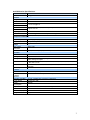
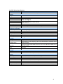
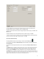
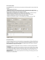
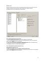
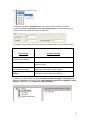
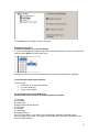
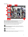
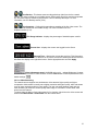
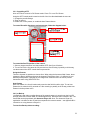
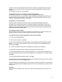
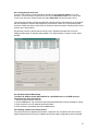
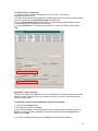
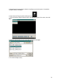
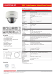
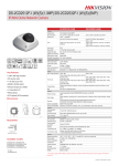
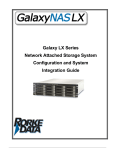
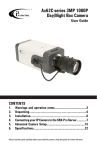
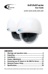
Ax32V Camera Series Instruction Manual CONTENTS INTRODUCTION ..................................................................... SPECIFICATIONS ............................................................... INSTALLATION.................................................................. 2 3 5 Before attempting to connect or operate this product, please read these instructions carefully and save this manual for future use. Annexxus Mini Network Dome Camera User Guide Ax32V Models All rights reserved. No part of this manual may be reproduced or transmitted in any form or by any means, electronic or mechanical, including photocopying, recording, or by any information storage or retrieval system, without the prior written permission of the copyright owner and the publisher. Annexxus is a registered trademark of i³ International. i³ reserves the right to change the contents of this manual without notice. Disclaimer Annexxus Mini Network Dome Camera User Guide is provided as is, without warranty of any kind, expressed or implied, including but not limited to performance, merchantability, or fitness for any particular purpose. Neither i³ International Inc. nor its dealers or distributors shall be liable to any person or entity with respect to any liability, loss, or damage, caused or alleged to have been caused directly or indirectly by this information. Furthermore i³ International Inc. reserves the right to revise this publication, and to make changes to the content at any time, without notice. FCC This device complies with part 15 of the FCC Rules. Operation is subject to the following two conditions: (1) This device may not cause harmful interference, and (2) this device must accept any interference received, including interference that may cause undesired operation. Address: i³ International Inc. • 780 Birchmount Road, Unit 16 • Scarborough • Ontario • Canada M1K 5H4 Tech Support: 1.877.877.7241 or email to: [email protected] Web Site: www.i3international.com 1 1 Introduction Thank you for purchasing an i³ Annexxus Network Camera. The Ax32V models are vandal-proof dome cameras that can be viewed on site or remotely. They come with i³’s Annexxus Web Viewer software which operates on an Internet Explorer web browser platform so is easy to install and offers a range of user-friendly video functions. The Ax32V cameras integrate perfectly into i³ International’s SRX-Pro DVMS systems. 1.1 Precautions Safety 1. This quick start guide is designed for users who have an adequate knowledge of network cameras. 2. Do not touch the imaging surface of the sensor. Use a soft cloth moistened with alcohol to clean the surface if it is touched accidentally. 3. Ensure the power supply voltage is correct for the particular variant of camera before operation. 4. Do not attempt to service this camera yourself unless you are authorized to do so. Opening the camera may expose you to electrocution or other hazards. Refer all servicing to qualified personnel only. 5. For more details on installation and operation, please refer to the CD provided. 1.2 Unpacking Camera Parts and Definition Hardware/Software Requirements 2 Ax32V2M series Specifications: Model Parameter Camera Image Sensor Electronic Shutter Min. Illumination Ax32V2M series 2 megapixel CMOS IP Vandal-Proof Indoor Dome Camera Lens 4mm, F1.2 Fixed Iris (2.8, 6, 8mm optional) Angle of view: 90° 1/3 inch CMOS 1/25s ~1/100,000s Color: 0.5Lux @ F1.2 B / W: 0.1Lux @ F1.2 Day / Night Electronic Video Parameter Saturation/Brightness/Contrast/ adjustable through client software or web browser Adjustment Range Pan±15°, Tilt0~90°, Rotation±15° Compression Standard Video Compression H.264/Mpeg4/MJpeg Bit rate 32 Kbps~16Mbps Audio Compression OggVorbis Image Max. Image 1600 x 1200 Resolution Frame Rate 15fps (1600 x 1200), 30fps (1280 x 720) Function e-PTZ Yes Storage Support NAS, ISCSI Intelligent Alarm Motion Detection, Video Tampering, Video Loss, Network Broken, IP address conflict, Storage exception Protocols TCP/IP,HTTP,DHCP,DNS,DDNS,RTP/RTCP,PPPoE,FTP,SMTP,NTP,SNMP,HTTP S, SIP, 802.1x, IPV6 Basic Initial Set button, Anti-flicker, Dual Stream, Heartbeat, Password Protection, watermark 3-Axis adjustment Yes Interface Audio Internal Microphone optional Communication 1 RJ45 10M / 100M self adaptive Ethernet port Interface General Operating Condition -10°~60°, Humidity 90% or less(non-condensing) Power Supply DC12V±10% / PoE Power 3W MAX Consumption Impact Protection IEC60068-275Eh,50J;EN50102, exceeding IK10 Weather Proof IP66 Dimensions(mm) 100×97.5×46.5 Weight 250g 3 Ax32VD1 Series Specifications Model Parameter Camera Image Sensor Electronic Shutter Min. Illumination Ax32VD1 Series VGA Real-time CMOS Mini IP Vandal-proof Dome Camera 1/4 inch CMOS 1/25s ~1/100,000s Color: 0.1 Lux @ F1.2 B / W: 0.01Lux @ F1.2 Lens 4mm, F1.2 Fixed Iris(2.8, 6, 8mm optional) Angle of view: 71° Day / Night Video Parameter Adjustment Range Compression Standard Video Compression Bit rate Audio Compression Image Max. Image Resolution Frame Rate Function Storage Electronic Saturation/Brightness/Contrast/ adjustable through client software or web browser Pan±15°, Tilt0~90°, Rotation±15° Intelligent Alarm Protocols H.264/Mpeg4/MJpeg 32 Kbps~8Mbps OggVorbis 640×480 30fps @ 640×480 Support NAS, ISCSI Motion Detection, Video Tampering, Video Loss, Network Broken, IP address conflict, Storage exception TCP/IP,HTTP,DHCP,DNS,DDNS,RTP/RTCP,PPPoE,FTP,SMTP,NTP,SNMP,HTTPS, SIP, 802.1x, IPV6 Initial Set button, Anti-flicker, Dual Stream, Heartbeat, Password Protection, watermark Yes Basic 3-Axis adjustment Interface Audio Communication Interface General Operating Condition Power Supply Power Consumption Impact Protection Weather Proof Dimensions(mm) -10°~60°, Humidity 90% or less(non-condensing) DC12V±10% / PoE 3W MAX IEC60068-275Eh,50J;EN50102, exceeding IK10 IP66 100×97.5×46.5 Weight 250g Internal Microphone optional 1 RJ45 10M / 100M self adaptive Ethernet port 4 2 Camera connection & Annexxus Installation Topics covered Connecting the network camera Network camera IP configurations Annexxus Web Viewer Installation and Setup details Annexxus Advanced Setup Note: Internet Explorer version 6.0 or higher is necessary to connect with an i3 International network camera. 2.1 Connecting a network camera Two methods of connecting a network camera and PC are shown below: Connection type: 1 Network camera Crossover direct connection i³ iP-Pro Server Connection type: 2 Network camera Network camera LAN VIA a Gigabit Switch Network camera i³ iP-Pro Server 2.2 Network Camera Default IP Configurations The RJ-45 Network Port on the network camera will connect to an Ethernet/Fast Ethernet standard (10/100Base-TX) network, complying with the IEEE 802.3U standard. Annexxus device may be connected to a hub, switch or router with a straight through CAT5e cable, or directly to the DVR/NVR with a crossover CAT5e cable. Network Settings: Ax32V Default IP configurations : IP Address: 192.0.0.16 Subnet Mask: 255.255.255.0 2.3 Annexxus Web Viewer Installation and Setup details Note: Internet Explorer version 6.0 or higher is necessary to connect with an i3 International network camera. 2.3.1 Installing Annexxus Web Viewer and accessing Setup mode 1. Connect the network camera to the supported power source in accordance with the connections diagram. 5 2. Connect the camera to a LAN/WAN network. 3. Before viewing, you may need to adjust your browser’s security settings. To do so: From the Tool menu, click Internet Options. Click on the Security tab. If the camera is using the intranet, click the Local intranet icon. If the camera is using the internet, click the Internet icon. Click on Custom level. Under ActiveX controls and plug-ins, enable the following three functions: ‘Download signed ActiveX controls’ ‘Run ActiveX control and plug-ins’ ‘Script ActiveX controls marked safe for scripting”. Click OK. 4. Open Internet Explorer browser window on a local PC/laptop and enter Annexxus IP address (192.0.0.16 for Ax32V) in the address line. 5. When connecting for the first time, you may be prompted to install Annexxus 300 Active X control. Click on the banner and select install the following Active X control ‘Annexxus 300’ from ‘I3 International Inc.’... from the context menu. 6 6. In the Internet Explorer - Security Warning window, click Install. 7. The Annexxus Web Viewer screen will be displayed with the Login window. Enter Annexxus Username and Password and click Login. Note The login is case sensitive. The default administrative login is: Username: admin; Password: 1234 8. Annexxus Web Viewer opens and a live view from the camera appears. 9. To adjust parameters click the Setup button on the main screen Advanced Setup section (s.2.4) of this manual for more information. . See the Annexxus 2.3.2 Changing IP Address Your Ax32V2M series Network camera comes with the pre-assigned IP scheme: IP Address 192.0.0.16; Subnet mask: 255.255.255.0 To change camera IP Address: 1. Install Annexxus Active X as in section (2.3). Open and login to Annexxus. 2. Click the Setup button on the main screen and open the Network setup tab. 3. In the Network setup tab, configure IP settings, such as IP Address and Subnet Mask for LAN connections or IP Address, Subnet Mask, and Gateway IP for WAN connections. It is entirely the responsibility of a technician to be able to configure this setup page according to customer’s network configurations. 7 4. Click the Save button and wait for the "Settings changes have been successfully saved” message window to pop up. Click OK to close the message window. 5. Wait for “Please reboot Annexxus device to apply changes” window to pop up. Click OK. Click Reboot button. 6. Wait for “Would you like to reboot Annexxus device?” window to pop up. Click OK. 7. Wait for “Annexxus device is rebooting. Close Internet Explorer browser, wait 45 seconds and connect to Annexxus Viewer again” window to pop up. Click OK. 2.4 Annexxus Advanced Setup To change additional network camera settings, click the Advanced Setup button . Four setup tabs are available in Advanced Setup: Device Information, Channels, Network and User Management. In the bottom of each setup window there are four control buttons: Restore, Reboot, Save and Close. The Restore button is available to authorized users only. Click it to restore the Annexxus device settings to the factory default settings. Settings must be restored to factory default after each firmware upgrade. WARNING: All custom settings will be lost, including any additional users. The Reboot button is available to authorized users only. Click it to reboot the Annexxus device. A device reboot is required after the video recording settings have been changed or after a firmware upgrade. Read related section for instructions on rebooting the device. 8 The Save button is available to authorized users only. Click it to save any setting changes. To prevent unauthorized users from making changes to the Annexxus device, disable the Save button in the User Management setup tab. The Close button closes the Advanced Setup window. 2.4.1 Device Information Setup The following information about the Annexxus device can be found in the Device Information setup: the number of video channels, sensor inputs, control outputs and internal storage devices connected to the network, the current device firmware version and the device’s serial number. Authorized users can also assign/change the device name, change the overwrite mode and upgrade the device's firmware version. V3.0 build 10/206 NOTE: Overwrite Mode only functions when used in conjunction with SRX-Pro software. Device Name In Device Name, enter the camera’s custom name. Firmware Upgrade This function is only available to authorized users. Read the Upgrading Firmware section for instructions on how to upgrade Annexxus device firmware. 9 2.4.2 Channels Setup In the Channels Setup, authorized users can perform the following tasks for each selected video channel: • Assign/change channel name. • Display/hide channel name, change the position of the channel name on the video screen. • Display/hide timestamp and day of the week; change the position of the timestamp on the video screen; change the display style of the timestamp if enabled. • Display/hide up to 4 personalized text messages on the video screen – called text overlay. • Enable video privacy masking, set up to 4 video privacy masking areas. • Change the display and recording resolution for the main and sub video streams. • Change the display frame rate for the main and sub video streams. • Change other transmission settings: I Interval, BitRate Type, BitRate, and Frame Type. 2.4.3 Network Setup The RJ-45 Network Port on the IP camera allows it to be connected to an Ethernet/Fast Ethernet standard (10/100Base-TX) network, complying with the IEEE 802.3U standard. Annexxus device may be connected to a hub, switch or router with a straight through CAT5e cable, or directly to the DVR/NVR with a crossover CAT5e cable. See Annexxus Default IP Configurations section for information on Annexxus factory default IP configurations. In the Network Setup, authorized users can obtain the network camera's MAC Address; change its IP Address, Subnet Mask, Gateway IP, Multicast IP, Host Port (for Video/Audio) and/or HTTP Port (for Web access). Please contact your network administrator for more information on your network particulars. Important: Make sure to open all ports required for remote viewing. The following ports must be forwarded: 80, 554, 8000, 8200. 10 Unique IP address must be assigned to each Annexxus unit before installation. Unless this step is completed prior to installation, the customer will be unable to detect Annexxus module on their LAN/WAN network. See Changing IP Address section for instructions on how to change Annexxus IP address. It is highly recommended to click Synchronize Clock to synchronize the camera to the time zone in which it is used. If this isn’t done the time stamp on snapshots will not match the time of the time zone. 2.4.4 User Management Setup One administrator account and up to 15 additional accounts can be configured for the network camera. Administrator user The default administrator user name is admin; the default password is 1234. The Administrator is the only user that can change the administrator password. The administrator user name and user privileges cannot be changed. If the administrator password is lost after being changed, use Annexxus Finder to reset it to the factory default. The administrator is the only user that can add, modify or delete additional operator users. 11 Operator user Operator users will only have access to setup tabs and features that are specified in their user privileges. Operator users cannot add, modify or delete other operator accounts. An operator user can only change his/her own password. 2.4.4.1 Changing Administrator Password To change the administrator password, you must be logged in as Administrator. 1. In the User Management setup tab, right-click on the Administrator account in the left-hand pane and select Modify from the context menu. 2. Type in the new password in Password and Re-enter Password fields. The password may only consist of numbers and may not exceed 16 characters. 3. Click Save to save the new administrative password. 2.4.4.2 Adding/Modifying/Deleting Operator User Adding/Modifying Operator User To add a new operator user or to modify an existing operator user: 1. In the User Management setup tab, right-click on the desired Operator account in the left-hand pane and select Modify from the context menu. 12 2. Enter the user name in User Name field. User name may not exceed 16 characters. 3. Enter the password in Password and Re-enter Password fields. The password may only consist of numbers and may not exceed 16 characters. 4. Configure user privileges. The following privileges can be assigned to the operator user(s): User Privilege Privilege Limitation Live Video Viewing (configured per channel) Check off to allow the operator to view live video. Save Settings Check off to allow the operator to make changes to Annexxus setup. Control PTZ (only applies to Ax32V2M series model) Upgrade, Format, Reboot Check off to allow operator to control the camera’s electronic Point/Tilt/Zoom (ePTZ) function. Check off to allow the operator to upgrade the camera firmware or to reboot the Annexxus device. To assign Live Video Viewing, check off Check Mark to Enable Privilege for Channel(s) then make sure Channel 01 is checked. For the Save Settings, Control PTZ and Upgrade, Format, Reboot privileges check off Check Mark to Enable Privilege. 13 5. Click Save to save changes to all user accounts Deleting Operator User To delete an operator user, do the following: 1. In the User Management setup tab, right-click on the desired Operator account in the left-hand pane and select Delete from the context menu. Note that the user will be deleted immediately and no warning message will be displayed. 3 Using Annexxus Web Viewer Interface Topics covered: Introduction to Annexxus Web Viewer Live video streaming Taking a live snapshot 3.1 Introduction to Annexxus Web Viewer Annexxus Web Viewer contains the following buttons and areas: 1. Live Mode 2. Setup Mode 3. Login/Logout 4. Single Camera Screen Division 5. Full Screen 6. Snapshot 7. Live Backup 8. ChannelsTree List 9. ePTZ Control Panel – only applies to Ax32V2M series; disabled for Ax32VD1 Series 10. Video Adjustments Panel – only applies to Ax32V2M series; disabled for Ax32VD1 Series 11. CPU Usage Indicator 14 12. Current User 13. Current Date and Time 1 2 3 4 5 6 7 8 9 10 11 12 13 Note: The Audio Settings panel at the bottom left of the live view screen is disabled, because neither the Ax32V2M series nor the Ax32VD1 series capture sound. Note: The PTZ Control panel on the left side of the live view screen is disabled for the Ax32VD1 series, because this model does not support the PTZ or ePTZ function. Note: The Video Adjustments panel on the left side of the live view screen is disabled for the Ax32VD1 series, because this model does not support the video adjustments function. The Annexxus Web Viewer contains the following buttons and areas: Live Mode – displays the Annexxus Live mode. In Live mode, the user can control the ePTZ function, adjust brightness/contrast/hue/saturation settings and save live snapshot or video backup onto the local media storage. Setup Mode– displays Annexxus setup options. Full Screen - This button enlarges the live screen to fit your computer screen with no user interface (no menu bars shown). To exit press F11 on your keyboard. 15 Live Backup - This button starts recording a backup video from the live network camera. The video is saved on local media storage. Each backup file will be saved as a separate file. Annexxus Player is needed to play back the *.axv live backup video clips. For more information, see Live Backup section (s.3.4). Live Snapshot – Clicking this button takes a snapshot of the live video screen. The snapshot will be saved onto local media storage. For more information see Live Snapshot section (s.3.5). CPU Usage Indicator - displays the percentage of hard disk space used for video display. Current User - displays the current user logged into the Server. Date and Time – displays the current date and time. This information is acquired from Windows OS. If date/time is not correct, access the desktop and double-click the Windows time display in the right-hand corner. Set the appropriate time and click Apply. Video Adjustments panel (Ax32V2M series only) - adjusts Brightness, Contrast, Hue and Saturation of the live video channel. Click the Undo button to reset all parameters to the default settings. 3.2 Live Video Streaming The network camera supports two simultaneous video streams: higher quality and higher compression. Main stream is usually set to higher resolution and higher quality, while sub stream is set to lower resolution and/or to lower quality. The user can switch between main and sub video streaming to either see a better quality video image or to be able to view a faster video stream over the Internet. To select either the Main or Sub video stream for live viewing, right-click on the video screen and select either Main stream or Sub stream from the context menu. 16 3.3 Electronic Pan/Tilt/Zoom (ePTZ) - Ax32V2M series only Through the Annexxus Web Viewer, authorized users can control the Electronic Pan/Tilt/Zoom (ePTZ) function of the network camera remotely. The ePTZ function does not apply to the Ax32VD1 series model. Make sure to properly connect the camera according to the Annexxus connections diagram. The network camera ePTZ can be controlled through the Annexxus Web Viewer or through the SRX-Pro/iP-Pro software (see SRX-Pro/iP-Pro software manual for more information). It is important to note that certain image resolution levels affect the functioning of ePTZ. On certain resolution levels ePTZ does not function at all. Figure 3.3 below indicates how resolution affects ePTZ: Figure 3.3 352x240 / 352x288 640x480 704x480 / 704x576 800x600 ePTZ fully functional 1280x720 1280x960 No In/Out Zoom function 1600x912 1600x1200 ePTZ does not function 17 3.3.1 Controlling ePTZ Note: ePTZ does not work in Full Screen mode. Press F11 to exit Full Screen. Using the ePTZ control panel located on the left of the live video dashboard the user can: 1. Change the pan-tilt settings. 2. Zoom in and out. 3. Enable one of nine presets, or enable the Auto Pattern feature. To control Zoom/Iris direction or activate presets, follow the diagram below: To control the Pan/Tilt position of the camera: 1. Select a camera resolution level that enables ePTZ. See figure 3.3 above. 2. To use Pan/Tilt, the iris cannot be fully zoomed out. After zooming in partially or all the way, use the arrows on the ePTZ control wheel to pan and tilt. Using the Presets There are 9 preset iris positions to choose from. When using the Annexxus Web Viewer, these presets are factory defaults and cannot be changed. Each preset, from 1-9, shifts the iris to a different preset position, changing the live image view. Note that users can set the presets themselves when using SRX-Pro/IP-Pro. Auto Pattern With Auto Pattern, the iris will continuously scan the view field from left to right. To use Auto Pattern the iris cannot be fully zoomed out. After zooming in partially or all the way, select Auto Pattern in the drop down menu. 3.4 Live Backup Live Backup is the video recording feature of the network camera. It records onto the local PC storage (local HDD, network HDD, or USB storage device). Recorded video is saved in the *.axv format and can be played back with Annexxus Player 2.0. Note: The Annexxus Player 2.0 application is included on the CD which accompanies the network camera – see Appendix B for instructions on using Annexxus Player 2.0. To start Live Backup video recording: 18 1. Click the Live Backup button on the main screen displayed. . The Live Backup window will be 2. In the Live Backup window, ensure the Channel 1 box is checked off. 3. Select Storage Location. Click Browse..., locate and select the destination folder on a local or network hard drive, where the *.axv live video backup files will be stored. The default location is C:\IP_Module_Recording. 4. Click OK to start the live video backup. The Live Backup button on the main screen will turn blue to indicate that a live backup is in progress. *.axv file is created in the storage location folder. Each time a live backup is initiated, a new The video backup files are named according to the following standard: IPADDRESS_CHANNEL_YYYYMMDD_HHMMSS.axv. For example, the video file 192.0.0.16_01_20100909_152712.axv was recorded from a Ax32V2M series network camera located on the 192.0.0.16 IP address (the default IP address for the camera), Video Channel 1, September 9, 2010 at 3:27PM. To stop Live Backup video recording for one or more channels: 19 1. Click the Live Backup button on the main screen displayed. The Live Backup window will be 2. In the Live Backup window, ensure the Channel 1 box is unchecked. If the Channel 1 box remains checked, recording will continue! Click OK. The Live Backup button will return to its normal colours (yellow on black) to indicate that recording has stopped. 3.5 Taking a Live Snapshot Live Snapshot takes an instant *.bmp snapshot of the video channel and saves it to the local PC storage (local HDD, network HDD, or USB storage device). The default location is C:\IP_Module_Snapshot. The saved *.bmp snapshots can be opened with any standard Windows image viewer. To take a Live Snapshot: 1. Click the Live Snapshot button on the main screen displayed. . The Snapshot window will be 2. In the Snapshot window, select Storage Location . Click Browse... , locate and select the destination folder on a local or network hard drive, where the *.bmp live snapshot files will be stored. The default location is C:\IP_Module_Snapshot. 20 3. Make a note of the new snapshot File Name. Each snapshot is assigned a random number attached to the end of the file name to distinguish between snapshots taken within the same second. 5. Click OK to save the the *.bmp snapshot. The snapshot files are named according to the following standard: IPADDRESS_CHANNEL_YYYYMMDD_HHMMSS_RANDOMNUMBER.bmp. For example, a 192.0.0.63_01_20100920_113425_7998234.bmp snapshot was taken from an Annexxus 32VD14 network camera on the 192.0.0.63 IP address (default IP address), Video Channel 1, September 20, 2010 at 11:34:25 AM. 4 Appendixes – Annexxus Finder Annexxus Finder locates all Annexxus cameras on the network and displays important information about each individual device, including IP Address, Subnet Mask, Port number, Firmware version, and MAC Address. Use the Annexxus Finder application to configure the IP Address and the Subnet Mask for the detected Annexxus devices as well as reset the devices’ passwords to the factory default 1234. 4.1 Installing Annexxus Finder Each Annexxus Network camera is accompanied by the Resource CD. Insert the CD into your system's CD drive. On the CD, locate and open the Annexxus_Finder folder. To install the Annexxus Finder application, follow the steps below: 1. Double-click the Setup.exe file. 2. In the first setup window, click Next. 3. In the Select Installation Folder setup window, select installation drive and folder by clicking Browse... or keep the default installation folder (recommended). Select the Everyone radio button and click Next. 4. In Confirm Installation setup window, click Next to proceed with the installation. 5. Wait while the Annexxus Finder software is installing onto the local system. 6. The WinPcap installation will be automatically launched. You must install WinPcap library for the proper functioning of the Annexxus Finder application. In the WinPcap 4.0.2 Installer window, click Next. 7. In the following WinPcap installer window, click Next. 8. In the WinPcap License Agreement window, read the WinPcap license terms (scroll to read the entire document). Then click the I Agree button. 9. Wait while WinPcap is installing onto the local system. Wait for the Installation Complete setup window to be displayed and click Close. Annexxus Finder is now installed on your system and is ready to use. Important To virus protection software users: make sure to allow the WinPcap library to operate on your system. 21 4.2 Locating Annexxus Devices To launch the Annexxus Finder application, double-click the Annexxus Finder icon on the Desktop. For the Annexxus-series User Guide, click the Annexxus Finder icon in the top left corner of the Annexxus Finder window and select Help Index from the drop-down menu. Launch Annexxus Finder. All Annexxus Network cameras and 301-series devices on the network will automatically be detected and displayed in the Annexxus Finder list. In the example below, Annexxus Finder was able to locate three (3) Annexxus network cameras, including Ax32V series camera on the local network. By selecting a device in the list with the mouse cursor, detailed information about it will be displayed underneath: IP Address, Subnet Mask, Port, MAC Address, Firmware version, Serial Number. 4.3 IP Address/Subnet Mask Setup To edit the IP Address and/or Subnet Mask for a Ax32V2M series or Ax32VD series (or other Annexxus 301-series device): 1. Select the desired device in the list 2. Click the Edit button. The IP Address and Subnet Mask fields will becomes enabled for editing. 3. Enter the device's new IP Address and Subnet Mask. 4. Enter the device's password and click the Save button. 4.4 Resetting Password to Factory Default If an Annexxus device's password is unknown or has been lost, it needs be reset to the factory default setting before the device's IP Address and Subnet mask configurations can be changed. 22 To reset the device's password: 1. Contact our technical support department at 1.877.877.7241 or by email, at [email protected]. 2. Inform our technical support representative that the password for your Annexxus device needs to be reset. Write down the Authorization Code provided to you. 3. Enter the Authorization Code obtained from our technical support representative into the corresponding field in the Annexxus Finder window. 4. Click the Submit button. The device's password will be reset to the factory default setting: 1234 Appendix B – Annexxus Player The Annexxus Player video application comes on the Resource CD that accompanies the Ax32V network cameras. Insert the CD into your system's CD drive. On the CD, locate and open the Annexxus_Player folder. To install the Annexxus Finder application, follow the steps below: 1. Double-click the Setup.exe file. 2. In the first setup window, click Next. 3. In the Select Installation Folder setup window, select installation drive and folder by clicking Browse... or keep the default installation folder (recommended). Select the Everyone radio button and click Next. 4. In Confirm Installation setup window, click Next to proceed with the installation. 23 5. Wait while the Annexxus Player software is installing onto the local system. In Installation Complete window, click Close. . 6. Open Annexxus Player by double clicking the icon 7. Once the Annexxus Player window is open, click File at the top left of the screen, then click Open. 8. Select the desired video from the menu that appears and click Open. 9. The video will begin to play. 24 Note: the volume slider and mute button on the Annexxus Player viewer do not function when recordings are done with the Ax32V2M series and Ax32VD1 series network cameras because these models do not capture sound. 7. Control the video using the buttons at the bottom of the Annexxus Player viewer: NOTE: The default storage file for snapshots taken with Annexxus Player is not the same as for snapshots with the Annexxus Web Viewer interface. Similarly, they do not follow the same naming standard. Snapshots taken from Annexxus Player will automatically be saved to the C: drive and will be named snapshot01.bmp, snapshot02.bmp, etc. (For instructions on live video snapshots with the Annexxus Web Viewer interface, refer to section 3.5 of this manual). 25 Appendix C- Upgrading Firmware Annexxus cameras and systems are always shipped with the newest available firmware and do not need a firmware update. However, in the unlikely event that the firmware will need to be upgraded in the future, follow the instructions below. Important: Firmware may only be upgraded by the administrative user. For firmware update: 1. Open the Annexxus Web Viewer application. 2. Click the Setup button. 3. In the Device Information setup tab, select the Firmware Upgrade radio button. 3. Click Browse... and then locate and select the newest *.anx firmware file and click Open. 5. Click Upgrade. The remote Upgrade Status message will change to "Device is updating, please wait!" 6. Wait until the Status message changes to "Update completed!" 7. Click the Restore button in the bottom left corner of the Setup window to apply default settings from the new firmware package. All custom settings will be erased. 8. Click OK in the Warning message window shown below. 9. The "Upgrade completed, please reboot device!" message will be displayed. Click OK to close it. 10. Reboot the Annexxus the camera. 11. Close the Annexxus Web Viewer and open a new Internet Explorer window. 12. In the IE window, go Tools -> Properties. The Internet Options window will be displayed. 26 13. In the Internet Options window, click Settings under Browsing history. A Temporary Internet Files and History Settings window will be displayed. 14. In the Temporary Internet Files and History Settings window, click View objects. A Download Program Files folder window will be displayed. 15. Remove the i³ Annexxus ActiveX control and re-connect to the Annexxus camera via Internet Explorer. 16. Download new ActiveX control and log in. The new firmware and new firmware settings have now been applied to the Annexxus network camera. 27