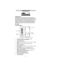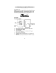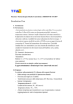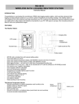
1
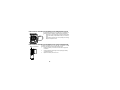
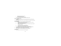
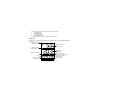
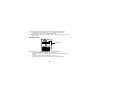
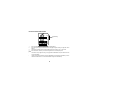
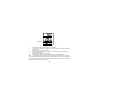
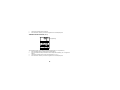
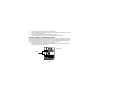
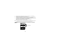
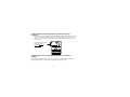
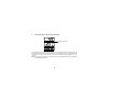
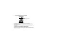
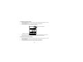
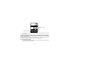
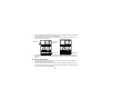
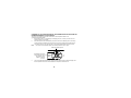
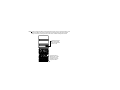
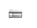
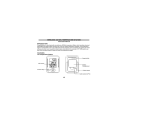
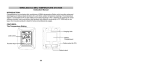
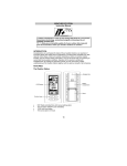
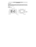
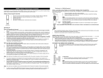
WIRELESS 433 MHz TEMPERATURE STATION
Instruction Manual
Cat. No. 30.3015
Thank you for choosing this wireless temperature station from TFA.
BEFORE YOU USE IT
Please be sure to read the instruction manual carefully.
This information will help you to familiarise yourself with your new device, learn all of its functions and
parts, find out important details about its first use and how to operate it, and get advice in the event of
faults.
Following the instruction manual for use will prevent damage to the device and loss of your statutory rights
arising from defects due to incorrect use.
We shall not be liable for any damage occurring as a result of not following these instructions.
Likewise, we take no responsibility for any incorrect readings and for any consequences which
may result from them.
Please take particular note of the safety advice!
Please look after this manual for future reference.
SCOPE OF SUPPLY:
•
•
Temperature station (basic unit)
Instruction manual
FIELD OF OPERATION AND ALL OF THE BENEFITS OF YOUR NEW TEMPERATURE
STATION AT A GLANCE
•
DCF radio controlled time with manual setting option
48
•
•
•
•
•
•
•
•
•
•
•
•
•
•
•
•
Time zone option ±12 hours
Indoor and outdoor temperature display with MIN/MAX records and time of reception
Indoor and outdoor humidity display as RH% with MIN/MAX records
Data logging function – with adjustable recording intervals, can store up to 3000 sets of
Temperature/Humidity data
Connectable to PC (Com port) – data can be transferred to PC with the software (in CD ROM)
provided
Can receive up to 5 outdoor transmitters
Time reception ON/OFF selectable
Dew point temperature displayed
Temperature & humidity High/Low alarm function
12/24 hour time display
Year/ Month/ Day calendar display
Temperature display in ºC/ ºF
LCD contrast selectable
Temperature and humidity calibration function
Low battery indicator
Table standing or wall mounting
FOR YOUR SAFETY:
•
•
•
The product is exclusively intended for the field of application described above. The product should
only be used as described within these instructions.
Unauthorised repairs, modifications or changes to the product are prohibited.
The product is not to be used for medical purpose or for public information, but is intended solely for
home use.
49
Caution!
Risk of injury:
•
•
•
Keep this instrument and the batteries out of reach of children.
Batteries must not be thrown into the fire, short-circuited, taken apart or recharged. Risk of
explosion!
Batteries contain harmful acids. Low batteries should be changed as soon as possible to prevent
damage caused by a leaking battery. Never use a combination of old and new batteries together or
batteries of different types. Wear chemical-resistant protective gloves and glasses when handling
leaked batteries.
! Important information on product safety!
•
•
Do not expose the instrument to extreme temperatures, vibration or shock.
Protect from moisture.
50
ELEMENTS:
The temperature station
Hanging Hole
LCD screen
Battery
Compartment
Function keys
Foldout stand
Cable socket (to PC)
The outdoor transmitter (purchased separately)
•
•
•
•
Remote transmission of outdoor temperature and humidity to
temperature station by 433 MHz
Shower proof casing
Wall mounting case
Mounting at a sheltered place. Avoid direct rain and sunshine
Stand
51
HOW TO INSTALL AND REPLACE BATTERIES IN THE TEMPERATURE STATION
SIZE AA LR6
SIZE AA LR6
SIZE AA LR6
The temperature station uses 3 x AA, IEC LR6, 1.5V batteries. To
install and replace the batteries, please follow the steps below:
1.
Insert finger or other solid object in the space at the bottom
center of the battery compartment and lift up to remove the
cover.
2.
Insert batteries observing the correct polarity (see marking).
3.
Replace compartment cover.
HOW TO INSTALL AND REPLACE BATTERIES IN THE OUTDOOR TRANSMITTER
Battery compartment
The outdoor transmitter uses 2 x AA. IEC LR6, 1.5V batteries. To install
and replace the batteries, please follow the steps below:
1.
Remove the battery cover at the front side with an appropriate
screwdriver.
2.
Insert the batteries, observing the correct polarity (see battery
compartment marking).
3.
Replace the battery cover on the unit
52
BATTERY CHANGE:
User shall replace batteries of the temperature station when the battery low indicator is displayed at the
LCD. If user does not replace batteries, working error may be resulted.
Note:
•
•
•
After changing batteries in temperature station, there is no need for user to reset the temperature
station. In fact, the temperature station can remember all transmitter information and sequence as
per the pervious set-up. However, user may require to reset the desired LCD contrast, Alarm On/Off
condition, Calibration value and the Clock (by re-entering the date and time manually or simply wait
for the DCF time signal).
The “Average” value display for particular channel will only be calculated from the data after battery
change.
It is recommended to replace the batteries in all units on an annual basis to ensure optimum
accuracy of these units.
SETTING UP
1.
Insert batteries into the temperature station (see “How to install and replace batteries in the
temperature station” above). Once the batteries are in place, all segments of the LCD will light up
briefly. Then the indoor temperature and humidity will be displayed. The time will be shown 0:00 and
the date as 1.1.04.
Note:
If the indoor temperature and humidity are not displayed after 15 seconds, remove the batteries and wait
for at least 2 minutes before reinserting them. Also check if the battery has been used up. User is
recommended to use new alkaline batteries to the units.
There is a four-minute time for user to set up all transmitters one by one, after inserting batteries to the
temperature station. The below steps 2 to 4 shall be completed within this 4-minute time.
53
2.
3.
4.
5.
6.
7.
Insert batteries to the first transmitter. The temperature station will start learning the transmitter. The
outdoor Channel 1 (out 1) temperature and humidity readings will then be displayed. User may
observe the outdoor channel icon appear. (If this does not happen after 3 minutes, the batteries will
need to be removed from both units and reset from step 1.)
After the readings from the first transmitter (Channel 1) are successfully shown by the temperature
station, insert batteries to the second transmitter. The outdoor “Channel 2” temperature and
humidity readings will then be displayed. User may observe the outdoor channel icon appear.
Set up the third, fourth, and fifth transmitter (if applicable) one by one as described in the above
steps.
Please note that the unit’s built-in memory stores not only saved readings but also any integrated
transmitters on their respective channels. If after you start to use the unit not all transmitters are
being received, you can manually incorporate these one by one as described at
LEARNING/REMOVING A TRANSMITTER.
To free up a used channel for a new transmitter please proceed as described at point 4.
You can also do this for all channels at the same time by returning to the factory settings as
described at CLEARING ALL DATA AND SETTINGS OF THE TEMPERATURE STATION FROM
THE PERMANENT MEMORY.
Please note that this will delete all stored data.
The temperature station will also try to receive the DCF time signal (radio controlled) after the
transmitter signal reception.
If after 10 minutes, the DCF time has not been received, press and hold the OK () key for 3
seconds to enter the Set up mode for manual time setting. The clock of the temperature station will
automatically attempt to receive the DCF time at midnight. When this is successful, the received
time will override the manually set time. The date is also updated with the received time. (Please
refer also to notes on “Radio controlled Time Reception” and “Manual Setting”).
54
DCF-77 RADIO CONTROLLED TIME
The time base for the radio controlled time is a Cesium Atomic Clock operated by the Physikalisch
Technische Bundesanstalt Braunschweig which has a time deviation of less than one second in one million
years. The time is coded and transmitted from Mainflingen near Frankfurt via frequency signal DCF-77
(77.5 kHz) and has a transmitting range of approximately 1,500 km. Your radio-controlled temperature
station receives this signal and converts it to show the precise time in summer or wintertime.
The quality of the reception depends greatly on the geographic location. In normal cases, there should be
no reception problems within a 1500km radius of Frankfurt.
Once the outdoor reception test period is completed, the DCF tower icon in the clock display will start
flashing in the upper center. This indicates that the clock has detected that there is a radio signal present
and is trying to receive it. When the time code is received, the DCF tower becomes permanently lit and the
time will be displayed.
If the tower icon flashes, but does not set the time or the DCF tower does not appear at all, then please
take note of the following:
•
Recommended distance to any interfering sources like computer monitors or TV sets is a minimum
of 1.5 - 2 meters.
•
Within ferro-concrete rooms (basements, superstructures), the received signal is naturally
weakened. In extreme cases, please place the unit close to a window and/ or point its front or back
towards the Frankfurt transmitter.
•
During nighttime, the atmospheric disturbances are usually less severe and reception is possible in
most cases. A single daily reception is adequate to keep the accuracy deviation below 1 second.
55
FUNCTION KEYS:
Temperature Station:
There are 5 function keys in the Temperature Station:
Plus key
OK key
Mode
key
Alarm key
Minus key
OK key ( )
•
In normal display mode, press and hold for 3 seconds to enter the manual setting mode for the
following:
a.
LCD contrast level
b.
Time zone
c.
Daylight saving time (On/ Off)
d.
Radio-controlled time reception (On/ Off)
e.
12/ 24 hour Display
f.
Time setting (Hour and Minute)
g.
Calendar setting (Year, Month and Day)
h.
Temperature unit (°C/ °F) setting
56
•
i.
Recording intervals to memory (hr:min)
j.
Re-learning/ Removing channels
k.
Number of channels to be saved to memory
In view mode or alarm mode, press to go back to normal display mode
Plus (+) and Minus (–) key
•
•
In normal display mode, press to select a channel (the indoor sensor or one of the outdoor
transmitters)
Press to make adjustment (increase or decrease) in different manual settings and alarm setting
Mode key (mode)
•
•
•
•
•
In normal display mode, press to toggle between the following view mode:
a.
Maximum record of a selected channel (the indoor sensor or one of the outdoor
transmitters, depending on the user’s selection)
b.
Minimum record of a selected channel
c.
Average humidity and temperature readings of a selected channel (over the last 100
values stored in memory)
d.
The dew point temperature of a selected channel
e.
History readings in the memory of a selected channel
f.
Calibration mode of humidity and temperature of a selected channel
In alarm setting mode, press to activate/ deactivate the temperature and humidity alarm.
In manual setting mode, press to go back to normal display mode
Press and hold for 3 seconds to reset Min/ Max record of a particular channel
Press and hold for 5 seconds to reset Min/ Max record of all channels
Alarm key (al)
•
Press and hold for 3 seconds to enter the alarm setting mode.
57
•
•
In alarm setting mode, press to toggle between the following settings:
1.
high humidity alarm
2.
low humidity alarm
3.
high temperature alarm
4.
low temperature alarm
In manual setting mode, press to go back to normal display mode
LCD Screen:
The LCD screen is split into 4 sections displaying the relatively humidity, temperature, EPROM status and
Time/ Date.
Outdoor data signal
reception indicator
Relative humidity
reading in RH%
Outdoor transmitter
identification number
Temperature
reading in ºC/
ºF
Memory data display
(showing no. of sets of unread
data stored in memory)
Calendar display
Data recording interval
Time
Time reception icon
(for DCF time)
Buzzer-on icon
Low battery indicator
58
MANUAL SETTINGS:
In normal display mode, press and hold the OK key for 3 seconds to enter the manual setting mode for the
following:
a.
LCD contrast setting
b.
Time zone setting
c.
Daylight saving time On/ Off setting
d.
Radio-controlled time reception On/ Off setting
e.
12/ 24 hour format setting
f.
Time setting (Hour and Minute)
g.
Calendar setting (Year, Month and Day)
h.
Temperature unit (°C/ °F) setting
i.
Recording intervals to memory (hr:min)
j.
Relearning or removing a transmitter
k.
Number of sets of outdoor channel to be saved to memory of temperature station
LCD CONTRAST SETTING:
Digits flashing
59
The LCD contrast can be set within 8 levels, from LCD 0 to LCD7 (Default setting is “LCD 5”):
1.
In normal display, press and hold the OK () key until the digits “Lcd” starts flashing.
2.
Use the Plus (+) and Minus (–) key to view all levels of contrast.
3.
Select the desired LCD contrast. Confirm with the mode or Alarm (al) key to go back to the normal
display mode.
TIME ZONE SETTING:
Digits flashing
The time zone default of the temperature station is “0”. To set a different time zone:
1.
Press and hold the OK key until the digits “Lcd” starts flashing.
2.
Press shortly the OK key one more time to enter the time zone setting. The digits “Zo” will be
flashing.
3.
Use the Plus and Minus key to set the time zone (-12 to 12 hr).
4.
Press the Mode or Alarm key to confirm and go back to the normal display mode.
60
DAYLIGHT SAVING TIME SETTING
Digits flashing
1.
2.
3.
4.
Press and hold the OK key until the digits “Lcd” starts flashing.
Press shortly the OK key two times to enter the daylight saving time setting. The digit “dS” will be
flashing.
Use the Plus and Minus key to set the daylight saving time function to “On” or “Off” mode.
Press the Mode or Alarm key to confirm and go back to the normal display mode.
Note:
•
•
The function of day night time saving is only applicable to WWVB time reception within the areas
in the United States.
“dS off” means that the feature is off and the WWVB will not change times automatically. “dS On”
indicates that the feature is on and the WWVB will change times automatically.
61
TIME RECEPTION ON/OFF SETTING:
Digits flashing
In area where reception of the DCF time is not possible, the DCF time reception function can be turned
OFF. The clock will then work as a normal Quartz clock. (Default setting is ON).
1.
Press and hold the OK key until the digits “Lcd” starts flashing.
2.
Press and release the OK key three times to enter the time reception time setting. The digit “rEc”
will be flashing.
3.
Use the Plus and Minus key to set the time reception function to on or off mode.
4.
Press the Mode or Alarm key to confirm and go back to the normal display mode.
Note:
If the Time Reception function is turn OFF manually, the clock will not attempt any reception of the DCF
time as long as the Time Reception OFF function is activated. The time reception icon and the “DCF” icon
will not be displayed on the LCD
62
12/24-HOUR FORMAT SETTING:
Digits flashing
The time display can be selected to show hours in 12-hour or 24-hour settings. (Default 24-Hour)
1.
Press and hold the OK key until the digits “Lcd” starts flashing.
2.
Press and release the OK key four times to enter the time format setting. The digit “24h” will be
flashing.
3.
Use the Plus and Minus key to set the time shown in 12-hour or 24-hour format.
4.
Press the Mode or Alarm key to confirm and go back to the normal display mode.
MANUAL TIME SETTING:
In case the temperature station cannot detect the DCF-signal (for example due to disturbances,
transmitting distance, etc.), the time can be manually set. The clock will then work as a normal Quartz
clock.
63
Hour flashing
Minutes flashing
1.
2.
3.
4.
5.
6.
Press and hold the OK key until the digits “Lcd” starts flashing.
Press and release the OK key five times to enter the hour setting. The hour digit in the time LCD
will be flashing.
Use the Plus and Minus key to set the hour.
Press the OK key one more time to confirm the hour and advance to the minute setting. The
minute digit will be flashing.
Use the Plus and Minus key to set the minute
Press the Mode or Alarm key to confirm and go back to the normal display mode.
Note:
The unit will still try and receive the signal every day despite it being manually set. When it does
receive the signal, it will change the manually set time into the received time. During reception attempts the
DCF tower icon will flash. If reception has been unsuccessful, then the DCF tower icon will not appear but
reception will still be attempted the following hour.
64
CALENDAR SETTING:
Year
Date
Month
The date default of the temperature station is 1. 1. in the year 2004. Once the radio-controlled time signals
are received, the date is automatically updated. However, if the signals are not received, the date can also
be set manually.
1.
Press and hold the OK key until the digits “Lcd” starts flashing.
2.
Press and release the OK key seven times to enter the year setting. The year digit in the date LCD
will be flashing.
3.
Use the Plus and Minus key to set the year.
4.
Press the OK key one more time to confirm the year and advance to the month setting. The month
digit will be flashing.
5.
Use the Plus and Minus key to set the month.
6.
Press the OK key one more time to confirm the month and advance to the day setting. The day digit
will be lashing.
65
7.
8.
Use the Plus and Minus key to set the day.
Press the Mode or Alarm key to confirm and go back to the normal display mode.
TEMPERATURE UNIT SETTING (°C/ °F):
Digit flashing
The temperature display can be selected to show temperature data in °C or °F (Default °C).
1.
Press and hold the OK key until the digits “Lcd” starts flashing.
2.
Press and release the OK key ten times to enter the temperature unit setting. The “°C” digit will be
flashing.
3.
Use the Plus and Minus key to set the unit of temperature in °C or °F.
4.
Press the Mode or Alarm key to confirm and go back to the normal display mode.
66
RECORDING INTERVAL (hr:min) SETTING
Digits flashing
The time intervals at which the temperature and humidity data saved to memory can be set to one of the
following:
1-minute; 5-minute; 10-minute; 15-minute; 20-minute; 30-minute; 1-hour; 2-hour; 4-hour; 6-hour; 8-hour;
12-hour or 24-hour.
Your appliance has been developed and produced to the very latest technical standards. Unfortunately,
however, an error occurred in programming the time intervals.
The following intervals are out of line, as follows:
3-hour interval
Records every 4 hours
4-hour interval
Records every 6 hours
6-hour interval
Records every 8 hours
8-hour interval
Records every 12 hours
12-hour interval
Records every 24 hours
67
1.
2.
3.
4.
Press and hold the OK key until the digits “Lcd” starts flashing.
Press and release the OK key eleven times to enter minute setting of the recoding interval. The min
in the record LCD will be flashing.
Use the Plus and Minus key to set the desired recording interval.
Press the Mode or Alarm key to confirm and go back to the normal display mode.
LEARNING/ REMOVING A TRANSMITTER (CHANNEL)
After replacement of batteries of a particular transmitter, it is necessary to learn the transmitter again in the
learning mode. On the other hand, when user wants to decrease the number of transmitters to be applied,
he may remove the transmitter so that the data from this channel will not be displayed in the temperature
station. The below procedures describe how to “re-learn” or “remove” a channel:
1.
Press and hold the OK key until the digits “Lcd” starts flashing.
2.
Press shortly the OK key twelve times to enter Learn/ Remove setting of channels. The digits “Lrn”,
“CH” and the channel icons will be flashing.
Digit flashing
Flashing
68
3.
4.
5.
6.
7.
Note:
Press Plus to get in Learn/ Remove setting of channels. The channel icon “1” will be flashing.
Press OK key () to select another channel, if necessary (1-5).
Press Plus to set the selected channel to “Re-learn” state (The channel icon will flash in two places
on the display), or press Minus to remove the channel (The channel icon will disappear).
As soon as the in two places flashing channel number disappears, the reception icon will be flashing
in the top left corner. Insert the batteries in the respective transmitter.
After a short time (1 minute at the maximum) the transmitter should be linked.
Repeat the above steps for further channels, if necessary.
Once a channel is removed, the temperature station will be “disconnected” form the channel and
the data transmitted by this channel cannot be viewed at the temperature station.
THE NUMBER OF OUTDOOR TRANSMITTERS TO BE SAVED INTO THE SYSTEM
MEMORY
Digits flashing
69
Up to 5 outdoor transmitters can be received by the temperature station. User may decide the number of
transmitter data to be save to the permanent memory of the temperature station. For instant, user may
apply 5 transmitters but set to save the data only from particular 3 transmitters. To set the number of
transmitters whose data are to be saved in the system memory:
1.
Press and hold the OK key until the digits “Lcd” starts flashing.
2.
Press and release the OK key thirteen times to enter transmitter number setting. The digit “Enr” will
be flashing.
3.
Use the Plus and Minus key to select the number of transmitter to be used with the temperature
station (up to 5 transmitters)
4.
Press the OK key one more time to confirm and go back to the normal display mode.
Note:
•
•
•
If user has set “Enr = 2” and five transmitters are on, the data only from channel No. 1 and 2 will be
saved in the system memory. Similarly, if user set “Enr = 4”, data from channels No. 1 to 4 will be
saved.
On the other hand, if user has initially applied 5 transmitters but then remove the Channel 3, the
temperature station will thereafter display “--.-“ for Channel 3. And if the user has chosen “Enr = 3,
then data from Channel 1 to 3 will be stored in the memory, instead of Channel 1, 2 and 4. The data
stored in the memory for channel 3 will be “--.-“.
After the “Enr” number has been changed, the history data will be cleared and “mem” will be rest to
“000”.
TO EXIT THE MANUAL SETTING MODE
Press the Mode key or Alarm key to exit the manual setting mode anytime during the manual setting. The
mode will return to the normal time display.
70
TOGGLING BETWEEN DIFFERENT CHANNELS (INDOOR AND OUTDOOR
CHANNELS):
1.
Press the Plus or Minus key to toggle between the Temperature and humidity readings of the indoor
channel and the outdoor transmitter channel(s). The channel identification icon (“in”, “out 1”, “out 2”,
“out 3” … ) will be displayed at the upper right screen indicating that the particular channel is now
being selected.
The temperature and humidity
readings of Outdoor
transmitter No. 2 is now
shown
VIEWING VARIOUS TYPE OF TEMP/HUMDITY READINGS OF A SELECTED
CHANNEL:
After a particular channel (the indoor sensor or one of the outdoor transmitters) has been selected by
pressing the Plus or Minus key, the following modes of data may be viewed by user:
71
a.
The Max temperature and Max humidity
Max icon flashing
In normal display mode, press the Mode key once. The maximum temperature and maximum humidity
measured by the channel, and the date and time of the maximum temperature recorded will be displayed.
The “max” icon will be flashing.
72
b.
The Min temperature and Min humidity
Min icon flashing
In normal display mode, press the Mode key two times. The minimum temperature and humidity measured
by the channel, and the date and time of the minimum temperature recorded will be displayed. The “min”
icon will be flashing.
73
c.
The average value of the last 100 sets reading
Average icon flashing
In normal display mode, press the Mode key three times. The average temperature and humidity value of
the data which have been saved in the system memory will be displayed. The “avg” icon will be flashing. If
the channel is not set to be saved in the system memory, no average value will be estimated and “--.-“ will
be shown.
Note: The “Average” value displayed for particular channel will be calculated from only the new data being
recorded after battery change.
74
d.
The dew point temperature
Dew point temperature icon
In normal display mode, press the Mode key four times. The dew point temperature will be displayed next
to the flashing “td” icon.
75
e.
The history data sets of temperature and humidity
History data icon flashing
In normal display mode, press the Mode key five times. The “hist” icon will be flashing and the last
recorded temperature and humidity reading with the time of record will be displayed.
By pressing the Minus key, the previous sets of readings which were measured at the user-selected
recording intervals may be viewed.
If the channel is not set to be saved in the system memory, no history values will be displayed and “--.-“ will
be shown on LCD.
CALIBRATION OF TEMPERATURE AND HUMIDITY READING
The temperature station allows user to calibrate the displayed temperature and humidity readings by a
better reference. User may enter the correction of temperature reading and humidity reading in the range
of ±2°C and ±10% respectively.
76
To calibrate the humidity reading:
1.
2.
3.
Press the Plus or Minus key to select a channel (the sensor at the temperature station or one of the
outdoor transmitters)
Press shortly the mode key for six times. The calibration icon will be flashing.
Press the OK key once. The humidity digits will be flashing.
Humidity correction flashing
Calibration icon flashing
4.
Press the Plus or Minus key to set the desired correction for the humidity reading. Then press the
Alarm key to exit or the OK key to advance to the calibration of temperature reading.
To calibrate the temperature reading:
1.
2.
3.
Press the Plus or Minus key to select a channel (the sensor at the temperature station or one of the
outdoor transmitters)
Press shortly the Mode key for six times. The calibration icon will be flashing.
Press shortly the OK key two times. The temperature digits will be flashing.
77
Temperature correction
flashing
Calibration icon flashing
4.
Press the Plus or Minus key to set the desired correction for the humidity reading. Then press the
Alarm key to exit.
ALARM PROGRAMMING FOR INDOOR/OUTDOOR TEMPERATURE AND HUMIDITY
The temperature station will allow users to set a range of specific alarms to meet specific temperature and
humidity conditions set by the user.
For example, user may set the high and low temperature alarm point at 20 and 30 °C respectively. Then
the alarm will sound once the temperature is higher than 30.0 or lower than 20.0 °C.
To set the high humidity alarm:
1.
In normal display, press the Plus or Minus key to select a channel (the sensor at the temperature
station or one of the outdoor transmitters)
78
2.
3.
Press and hold the Alarm key for about 3 second to enter high humidity alarm setting. The humidity
digits, high limit icon and the alarm icon will start flashing.
Press the Mode key to select to “activate” or “deactivate” the high humidity alarm. (“Alarm On” or
“Alarm Off” icon will be displayed)
High limit icon
Humidity digit
flashing
Alarm On icon
4.
5.
Alarm Off icon
Press the Plus or Minus key to set the desired value of the high humidity alarm threshold point.
Press OK key to return to the normal display or press the Alarm key to enter the low humidity alarm
setting.
To set the low humidity alarm:
1.
2.
In normal display, press the Plus or Minus key to select a channel (the sensor at the temperature
station or one of the outdoor transmitters)
Press and hold the Alarm key for about 3 second to enter high humidity alarm setting. Then press
the Alarm key shortly one more time to enter the low humidity alarm setting. The humidity digits, low
limit icon and the alarm icon will start flashing.
79
3.
4.
5.
Press the Mode key to select to “activate” or “deactivate” the low humidity alarm. (“Alarm On” or
“Alarm Off” icon will be displayed)
Press the Plus or Minus key to set the desired value of the low humidity alarm point.
Press OK key to return to the normal display or press the Alarm to enter the high temperature alarm
setting.
To set the high temperature alarm:
1.
2.
3.
4.
5.
In normal display, press the Plus or Minus key to select a channel (the sensor at the temperature
station or one of the outdoor transmitters)
Press and hold the al key for about 3 second to enter high humidity alarm setting. Then press
shortly the Alarm key two more times to enter the high temperature alarm setting. The temperature
digits, high limit icon and the alarm icon will start flashing.
Press the Mode key to select to “activate” or “deactivate” the high temperature alarm. (“Alarm On” or
“Alarm Off” icon will be displayed)
Press the Plus or Minus key to set the desired value of the high temperature alarm point.
Press OK key to return to the normal display or press the Alarm to enter the low temperature alarm
setting.
To set the low temperature alarm:
1.
2.
3.
4.
In normal display, press the Plus or Minus key to select a channel (the sensor at the temperature
station or one of the outdoor transmitters)
Press and hold the Alarm key for about 3 second to enter high humidity alarm setting. Then press
shortly the Alarm key three more times to enter the low temperature Alarm setting. The temperature
digits, low limit icon and the alarm icon will start flashing.
Press the Mode key to select to “activate” or “deactivate” the low temperature alarm. (“Alarm On” or
“Alarm Off” icon will be displayed)
Press the Plus or Minus key to set the desired value of the low temperature alarm point.
80
5.
Press OK key to return to the normal display.
Note:
•
The alarm allow user to set individually the high or low threshold upon his requirements. For
example, the user can set the thresholds for temperature to 35°C (high) and 25°C (low), while only
activating high temp alarm and deactivating low temp alarm. In this case, the alarm will not trigger
when temp. is lower than 25°C yet will trigger when temp is higher than 35.0°C.
•
When the temperature or humidity is sensed to be out of the pre-set threshold value, the alarm will
sound and the alarm icon will be present on LCD. User may press any key to stop the buzzer. If no
key is pressed, the buzzer will beep for two minutes yet the alarm signal icon will still be flashing
until the temperature or humidity is within the pre-set range again.
•
Once an alarm is triggered, the display switches to the latest triggered channel. In addition, the high/
low limit icon and IN/ OUT icon is flashing as long as the alarm condition is met.
•
If an alarm is triggered, the alarm icon will be flashing until the temperature and humidity is back to
the conditions within the preset threshold values.
Alarm signal icon
appears as the
current temperature
or humidity is out of
the pre-set
threshold value
81
CLEAR DATA IN THE TEMPERATURE STATION
CLEARING THE MAX/MIN TEMPERATURE AND HUMIDITY DATA OF A PARTICULAR
CHANNEL
To clear the max/min data of a channel:
1.
Press the Plus or Minus key to select a channel.
2.
Press and hold the Mode key for 3 second. The maximum and minimum temperature/ humidity data
and the time of record will be reset to the current value.
CLEARING THE MAX/MIN TEMPERATURE AND HUMIDITY DATA OF ALL CHANNELS
To clear the max/min data of all channels:
1.
Press and hold the Mode key for 5 second. The maximum and minimum temperature/ humidity data
and the time of record will be reset to the current value.
CLEARING ALL STORED TEMPERATURE AND HUMIDITY DATA (FROM
TEMPORARY MEMORY OF THE TEMPERATURE STATION)
The on-going temperature and humidity data are stored at the ring buffer memory (a temporary memory
area where the latest data will displace the oldest data once the memory capacity is reached). To clear this
memory, the following step shall be performed:
1.
Press both the Plus key and OK key and hold for about 2 seconds. Only the temperature and
humidity records of all channels (indoor and the outdoor channels) will be cleared. So the average
and history data will no longer exist. The memory display will show “mem 000” after the data has
been cleared.
Note: The maximum/ minimum temperature and humidity datas will not be cleared.
82
CLEARING ALL DATA AND SETTINGS OF THE TEMPERATURE STATION FROM THE
PERMANENT MEMORY (FACTORY RESET)
The factory reset needs to be launched if malfunction on the temperature station occurs.
To reset the temperature station:
1.
Ensure that the unit is in normal display, not displaying max, min, or history. And the unit is not
making any DCF or HF reception.
2.
Press the OK, Plus, Minus and Mode key and hold for 3 seconds in following orders. The OK key
must be pressed and hold first, then the other three key must be pressed and hold also within 1s.
Then hold the four keys for 3 seconds until you see running digits at bottom right area of LCD.
Note:
If the reset is not successfully initiated, user shall try from above step 1. again
Press and hold OK key first
Immediately press these
3 keys at the same time.
Then hold the 4 keys
together for about 3
seconds.
3.
The running digits will be displayed for about 6 minutes, followed by the full segment display. User
is then required to remove and re-insert batteries to complete the restart the unit.
83
Note: All data in temperature station will be cleared after the factory reset. The permanent memory of the
temperature station will be reset and all the data (of all channels) stored. Also, all the previous
settings of the station including the date and time, alarm, calibration settings will be cleared.
The display will show
some running digits
when the temperature
station is reset.
Full segment will be
displayed- user need to
remove and re-insert
batteries to restart the
temperature station.
84
After batteries are re-inserted, the station will automatically launch the learn mode. The signal receipt
indicator will be displayed. User needs to set again the temperature station for the desired application.
(See ”SETTING UP” in previous clause)
Note:
•
•
If the battery level is low, the digits “No EPr” may be displayed on LCD after resetting, indicating that
the power is too low for the temperature station to function normally. In this case, the batteries shall
be replaced.
User is recommended to upload and save all the useful data to PC (if possible) before performing
the factory reset.
USING THE TEMPERATURE STATION WITH PC
With the aid of the software supplied, the temperature station may provide the following additional
functions to user.
1.
Importing data from temperature station to PC
2.
Printing the history file
Procedures to install the software to PC and application of the software are described in the user manual
of the PC software.
ABOUT THE OUTDOOR TRANSMITTER (PURCHASED SEPARATELY)
The range of the temperature transmitter may be affected by the temperature. At cold temperatures the
transmitting distance may be decreased. Please bear this in mind when positioning the transmitters. Also
the batteries may be reduced in power for the outdoor transmitter.
85
CHECKING FOR 433MHz RECEPTION
If the outdoor temperature data is not being received within three minutes after setting up (or outdoor
display show “- -. -” in the outdoor section of the temperature station after 3 failed attempts during
normal operation), please check the following points:
1.
The distance of the temperature station or transmitters should be at least 2 meters away from any
interfering sources such as computer monitors or TV sets.
2.
Avoid placing the transmitters onto or in the immediate proximity of metal window frames.
3.
Using other electrical products such as headphones or speakers operating on the 433MHz-signal
frequency may prevent correct signal transmission or reception. Neighbors using electrical devices
operating on the 433MHz-signal frequency can also cause interference.
Note:
When the 433MHz signal is received correctly, do not re-open the battery cover of either the transmitter or
temperature station, as the batteries may spring free from the contacts and force a false reset. Should this
happen accidentally then reset all units (see “SETTING UP” above) otherwise transmission problems may
occur.
The transmission range is around 100 meters from the outdoor transmitter to the temperature station (in
open space). However, this depends on the surrounding environment and interference levels. If no
reception is possible despite the observation of these factors, all system units have to be reset (see
“SETTING UP” above).
POSITIONING THE TEMPERATURE STATION:
The temperature station provides the option of table standing or wall mounting the unit. Before wall
mounting, please check that the outdoor temperature(s) can be received from the desired location(s). To
wall mount:
86
1.
2.
Fix a screw (not supplied) into the desired wall, leaving the head extended out
by about 5mm.
Away from the base and hang the station onto the screw. Remember to
ensure that it locks into place before releasing.
POSITIONING THE OUTDOOR TRANSMITTER
The outdoor transmitter is supplied with a holder that may be attached to a wall
with the screws supplied. To attach to the wall using screws, please follow the
steps below:
1.
Mark the wall using a pen through the holes in the holder to
obtain the exact drilling position.
2.
Drill holes in the wall at the points marked.
3.
Screw holder onto wall.
The mounting surface can affect the transmission range. If e.g. the unit is
attached to a piece of metal, it may either reduce or increase the transmitting
range. For this reason, we recommend not placing the unit on any metal
surfaces or in any position where a large metal or highly polished surface is in
the immediate proximity (garage doors, double glazing etc.). Before securing in
place, please ensure that the temperature station can receive the signal from the outdoor transmitter at the
positions that you wish to situate them.
87
CARE AND MAINTENANCE
•
•
Clean the instrument and the transmitter with a soft damp cloth. Do not use solvents or scouring
agents.
Remove the batteries if you do not use the product for a lengthy period.
TROUBLESHOOTING
Problems
No indication on the
temperature station
No transmitter reception
Display "---"
No DCF reception
Incorrect display
Solution
• Ensure batteries polarity are correct
• Change batteries
• Check batteries of external transmitter (do not use rechargeable
batteries!)
• Restart the transmitter and temperature station as per the manual
• Choose another place for the transmitter and/or the temperature
station
• Reduce the distance between the transmitter and the temperature
station
• Check if there is any source of interference
• Time reception setting “ON”
• Choose another place for the temperature station
• Manual time setting
• Wait for attempted reception during the night
• Change batteries
WASTE DISPOSAL
This product has been manufactured using high-grade materials and components which can be recycled
and reused.
88
Never throw flat batteries and rechargeable batteries in household waste.
As a consumer, you are legally required to take them to your retail store or to appropriate
collection sites according to national or local regulations in order to protect the
environment.
The symbols for the heavy metals contained are: Cd=cadmium, Hg=mercury, Pb=lead
This instrument is labelled in accordance with the EU Waste Electrical and Electronic
Equipment Directive (WEEE).
Please do not dispose of this product with other household waste. The user is obligated to
take end-of-life devices to a designated collection point for the disposal of electrical and
electronic equipment, in order to ensure environmentally-compatible disposal.
SPECIFICATIONS:
Temperature station
Temperature measuring range:
Indoor
: 0ºC to +59.9ºC with 0.1°C resolution
+32ºF to +139.8ºF with 0.2ºF resolution
(“- -” displayed if outside this range)
Humidity measuring range:
Indoor
: 1% to 99% with 1% resolution (“- -“ displayed if outside this range)
Indoor temperature checking intervals
: Every 15 seconds
Indoor humidity checking intervals
: Every 20 seconds
Power consumption: (alkaline batteries recommended)
Temperature station
: 3 x AA, IEC LR6, 1.5V
Dimensions (L x W x H):
Temperature station
: 94 x 35 x 127 mm
89
Transmitter (optional, Cat. No. 30.3125)
Temperature measuring range:
Outdoor
: -29.9ºC to +69.9ºC with 0.1°C resolution
-21.8ºF to +157.8ºF with 0.2ºF resolution
(“- -” displayed if outside this range)
Humidity measuring range:
Outdoor
: 1% to 99% with 1% resolution (“- -“ displayed if outside this range)
Outdoor temperature checking interval
: Every 5 minutes
Outdoor humidity checking interval
: Every 5 minutes
Transmission range
: up to 100 meters (open space)
Maximum number of transmitters that can be used
: 5
Power consumption: (alkaline batteries recommended)
Transmitter
: 2 x AA, IEC LR6, 1.5V
Dimensions (L x W x H):
Transmitter (purchased separately)
: 43 x 23 x 160 mm
TFA Dostmann GmbH & Co. KG, Zum Ottersberg 12, D - 97877 Wertheim
No part of this manual may be reproduced without written consent of TFA Dostmann. The technical data
are correct at the time of going to print and may change without prior notice.
DECLARATION OF CONFORMITY
Herewith we declare, that this wireless transmission device does comply with the essentials requirements
of R&TTE Directive 1999/5/EC.
A copy of the signed and dated Declaration of Conformity is available on request via [email protected].
www.tfa-dostmann.de
3/13
90