1
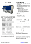
Field Logger Data Logger User Manual ABUS TECHNOLOGIES INC. Field Logger . WARNING This manual should be passed on to the end user. The contents of this manual are subject to change without prior notice. All rights reserved. ABUS gives no warranty of any kind with regard to this manual, including, but not limited to, fitness for a particular purpose. If any question arises or errors are found, or if any information is missing from this manual, please inform your supplier or inform at [email protected]. The specifications mentioned in this manual are limited to those for the standard type under the specified model number break-down and do not necessarily apply for customized instruments. Please note that changes in the specifications, construction, or component parts of the instrument may not immediately be reflected in this manual at the time of change. If the customer or any third party is harmed by the use of this product, ABUS assumes no responsibility for any such harm owing to any defects in the product which were not predictable, or for any indirect damages. Although Warning hazards are related to personal injury, and Caution hazards are associated with equipment or property damage, it must be understood that operation of damaged equipment could, under certain operational conditions, result in degraded process system performance leading to personal injury or death. Therefore, comply fully with all Warning and Caution notices. Information in this manual is intended only to assist our customers in the efficient operation of our equipment. Use of this manual for any other purpose is specifically prohibited and its contents are not to be reproduced in full or part without prior approval of Technical Communications Department, ABUS Technologies HEALTH AND SAFETY To ensure that our products are safe and without risk to health, the following points must be noted: 1. The relevant sections of these instructions must be read carefully before proceeding. 2. Warning labels on containers and packages must be observed. 3. Installation, operation, maintenance and servicing must only be carried out by suitably trained personnel and in accordance with the information given. Any deviation from these instructions will transfer the complete liability to the user. 4. Normal safety precautions must be taken to avoid the possibility of an accident occurring when operating in conditions of high pressure and/or temperature. 5. Chemicals must be stored away from heat, protected from temperature extremes and powders kept dry. Normal safe handling procedures must be used. 6. When disposing of chemicals ensure that no two chemicals are mixed. Safety advice concerning the use of the equipment described in this manual or any relevant hazard data sheets (where applicable) may be obtained from the Company address on the back cover, together with servicing and spares information. ABUS TECHNOLOGIES INC. 2 Field Logger CATALOGUE Contents Page No. 1. Introduction 4 2. Presentation 4 4 Technical Parameters 3. Dimensions 5 4. Ordering Details 5 5. Connections 6 6 Analogue Input 6. Installation 1. Input Signal 2. Alarm 7. Configuration 1. 2. 3. 4. Communication Page Channels Page Acquisitions Page Diagnosis Page 5. Serial Communication 7 7 7 8 8 9 10 12 13 15 15 8. Operation Data Logging 9. Safety Precautions 16 10. Warranty 16 ABUS TECHNOLOGIES INC. 3 Field Logger 1. INTRODUCTION The Field Logger is versatile data acquisition equipment for process variables, capable of on-line or stand alone operation. When loaded with a Real Time Clock and non-volatile memory, it can register up to 128k readings. Its universal input channels accept a large variety of sensors and standard signals as listed in table Field Logger Input Signals, below. A Configuration program (Windows 95, 98 or NT) is provided for an easy configuration of all the internal parameters. 2. PRESENTATION Technical Parameters Mains: Power consumption: 85 to 250 VAC (50/60Hz) or 100 to 250 VDC, or 24 VAC or VDC (optional) 2VA All sensors factory calibrated and software linearized. Internal cold junction compensation for thermocouples, 2 or 3 Wire Pt100. Pt100 input: 3 wire configuration with cable length compensation. Internal resolution: Linearity: Excitation current: 170A 20000 counts Better than 0.05% of FS Accuracy Thermocouple J, K, T, E and N: 0.2% of range ±1°C. Thermocouple R, S and B: 0.25% of range ±3°C. Pt100: 0.2% of range Linear voltage or current: 0.2% of maximum range RS485 interface (MODBUS RTU) o o Ambient temperature: 0 to 55 C (32 to 130 F) ABS case Dimensions: Weight: Alarms: 1059060mm 210 grams 2 SPST-NA - 3A / 250V relays ABUS TECHNOLOGIES INC. 4 Field Logger 3. DIMENSIONS 4. ORDERING DETAILS TYPE Product DESCRIPTION FL Field Logger 8-channel Universal Input N No Memory Storage Y 128K recording memory Recording Memory A AC: 85 ~ 250 Vac D DC: 24 V dc Supply Configuration Software SCADA Software -- Standard with Field Logger. N Without SCADA Software. 8 8-channel plotting & analysis software 8+ 64-channel plotting & analysis software. Example: FL > Y > A > -- > N ABUS TECHNOLOGIES INC. 5 Field Logger 5. CONNECTIONS Analogue Inputs Refer to figures Upper Side Connector and Lower Side Connector, below for connections of the input signals, power supply and alarm outputs. Upper Side Connector Lower Side Connector POWER –mains input VBAT – backup DC voltage (+6 to +24VDC). Allows continuous logging of data into memory when the AC voltage is absent. When the Field Logger is working with the VBAT power only, the serial communication and alarms are inhibited. ALM1 and ALM2 – output alarm relays DIG.IN – Digital input. A switch connected to this input acts as a “gate” for the logger (this function must be configured). The DIG.IN input shares one terminal with the VBAT input. ABUS TECHNOLOGIES INC. 6 Field Logger 6. INSTALLATION 6.1 Input Signal INPUT TYPE WORKING RANGE Thermocouple J -50 to 760°C (-58 to 1400 °F) Thermocouple K -90 to 1370°C (-130 to 2498 °F) Thermocouple T -100 to 400°C (-148 to 752 °F) Thermocouple E -35 to 720°C (-31 to 1328 °F) Thermocouple N -90 to 1300°C (-130 to 2372 °F) Thermocouple R 0 to 1760°C (-32 to 3200 °F) Thermocouple S 0 to 1760°C (-32 to 3200 °F) Thermocouple B 150 to 1820°C (302 to 3308 °F) Pt100 -200.0 to 530.0°C (-328.0 to 986.0 °F) 4-20mA type J -50 to 760°C (-58 to 1400 °F) 4-20mA type K -90 to 1370°C (-130 to 2498 °F) 4-20mA type T -100 to 400°C (-148 to 752 °F) 4-20mA type E -35 to 720°C (-31 to 1328 °F) 4-20mA type N -90 to 1300°C (-130 to 2372 °F) 4-20mA type R 0 to 1760°C (-32 to 3200 °F) 4-20mA type S 0 to 1760°C (-32 to 3200 °F) 4-20mA type B 150 to 1820°C (302 to 3308 °F) 4-20mA type Pt100 4-20mA -200.0 to 530.0°C (-328.0 to 986.0 °F) Indication range from -1999 to 9999 Field Logger Input Signals 6.2 Alarm The Field Logger has two relays (ALM1 and ALM2) which can be used as alarm outputs. They can also be used as digital outputs. In this case, a Modbus command controls its logical state. When it is used as alarms these relays can be associated to any input channel in an independent way. Two distinct alarm Set-points can be set to every input channel performing a HIGH (Maximum) or LOW (Minimum) functions. The HIGH alarm will signal when the input exceeds the value configured in the respective Setpoint. The alarm LOW will be ON whenever the input signal is below its respective Set-point. The alarms can be associated to any of the relays (or both). All input channels can share the same relay; the output which will perform an “OR” logic with all the requests. In the case where various channels use their alarms associated to the same output, the relay will be energized when any of the channels enters into an alarm condition, remaining so as long as at least one alarm is using it. ABUS TECHNOLOGIES INC. 7 Field Logger 7. CONFIGURATION A diskette with configuration software is included in the Field Logger package or can be downloaded from our web site www.abustek.com . It is also included with the FieldChart software, also available in the ABUS site. To install the Configurator, execute the program FL_Setup.EXE distributed in the diskette. The FieldChart software automatically installs the Configurator. The Configurator presents 4 pages for parameter configuration: Communication Channels, Acquisitions, and Diagnosis. 7.1 Communication Page When running the Configurator, first select the serial port (COM1 or COM2), as referred in the Communication page (See figure communication page, below). After setting up the communication port, the user can start the Field Logger configuration. Communication Page When an unknown Field Logger is to be configured (no information on baud rate or address), the Configurator can perform an ‘Automatic Search’ on the Field Logger connected to the PC COM port. It finds out the baud rate and address actually programmed in the Field Logger. To access this function, go to the Communication page and then click the button “Search”, in the “Automatic Search” box. The actual Field Logger communication parameters are shown, enabling the user to change them (for example, when configuring a network with many Field Loggers). To change the communication parameters, select new values for Baud Rate and Address and then hit the button “Modify”. The configuration program requires that only one Field Logger be connected to the PC when the “automatic search” utility is called. ABUS TECHNOLOGIES INC. 8 Field Logger The factory default for the communication parameters is: Baud rate = 9600 Address = 1 In a network, the baud rate must be the same for all instruments, and each instrument must have a unique address. The Configurator can talk to any Field Logger in the network, addressing one Field Logger at a time. After selecting a new address, and clicking in “Read Configuration”, the parameters of the selected Field Logger are read into the Configurator. To configure other Field Logger parameters, go to the Channels page. A screen similar to figure Channels Page is shown below. 7.2 Channels Page In the “Channel Selection” box, choose a channel to be configured. The parameters shown on the right side of the screen refer to the channel selected. The channels marked “Enabled” will be monitored (on-line monitoring) or logged into memory. A 16 character field (Title) is available for identifying the application. In addition, each channel can have a tag associated to it, up to 8 characters. The 8 input channels are universal, and it is allowed any combination of input types, that is, each channel can be configured independently from the others. Channel Page It is possible to adjust the indication range for the linear inputs (4-20mA and 0-50mV) by setting values to the high and low limits (-1999 to 9999). For example, when a 4-20mA input is being used and the range is set to 0-4000, the Field Logger will convert a value equal to 2000 for an input of 12mA. In addition, one can choose the number of decimals and associate an engineering unit to that input. For Thermocouples and Pt100, the ranges are fixed and represent the indication span of the sensor. The selection of the temperature unit (C or F) is available for these sensors. Each channel has ABUS TECHNOLOGIES INC. 9 Field Logger two alarms associated to it. Set-point values and alarm functions (HI or LO) are set in the Alarm 1 and Alarm 2 boxes, as well as the selection of the output relay for each alarm. If no relay is associated to an alarm, even so the alarm will be processed and informed to the supervisory software (refer to section – Serial Communication). The 2 relays may be configured as alarms, as mentioned previously, or as digital outputs, controlled by the MODBUS Preset Single Coil command, described in section- Serial Communication. When configured as digital output (see boxes “Relay 1 function” and “Relay 2 function”), the relay becomes unavailable to the alarms, even if an alarm was configured to use the relay. Returning the relay to the Alarm function, all previous alarm configurations will work again. The odd channels (1, 3, 5, and 7) can be configured as differential, as mentioned in sectionAnalogue Inputs. When a channel is configured as differential, the adjacent channel is also used; therefore, the respective even channel (2, 4, 6 or 8) is disabled in the configuration screen. 7.3 Acquisitions Page This page contains the parameters needed for recording data in the Field Logger internal memory. These parameters are: - Start Logging time - Stop Logging time. - Base Interval Between Loggings - Interval Multipliers for the channels (set individually for each channel). When a new logging configuration is transmitted, the current PC time and date is updated in the Field Logger. Note: Make sure the date and time in the PC is correct before sending a new configuration. The Field Logger is meant for measuring process variables, prioritizing accuracy and resolution over speed. The update rate for the input channels depends on the number of active channels and on the sensor type configured in each channel. It takes 50ms for an input to be converted (measured). Other internal measurements are needed for improving accuracy (offset suppression and gain calibration). Besides, cold junction compensation for thermocouples and cable length compensation for Pt100 measurements are also accomplished, depending on input channel configuration. An estimate update time for a single channel measurement is 0.2s. For 8 channels with thermocouple inputs, this time is 0.55s, whereas 8 Pt100 channels require 0.95s for the update. So, the time interval between loggings should not be set shorter than the total time required for reading the inputs. This time interval is defined by the Base Interval Between Loggings and the Interval Multipliers. The base interval can be specified from 0.2s to many hours and is common to all channels. The interval multiplier, however, can be configured individually for each channel, allowing distinct logging rates among channels. For example, for a base interval of 10s, a multiplier 1 will cause a new sample to be recorded every 10s; for a multiplier equal to 6, the channel will be recorded once every minute. Using ABUS TECHNOLOGIES INC. 10 Field Logger the multipliers, the user can manage the memory usage according to the importance of each input variable. The start and end of loggings can be accomplished in modes shown below: Remotely, through serial (Modbus) command: Select the option by serial command at the Start Logging parameter, and never stop for End Logging. Apply the configuration and then click the mouse in the button ‘Start now’. The logging will go on until the button ‘Stop now’ is hit. If the data memory is used up, it will wrap around, overwriting old data (circular memory). Remote start, end after a programmed number of base intervals: The logging is initiated as in the mode above, and goes on until a defined number of base intervals is reached. The logging can be stopped by a serial command or when the memory runs out of space. Remote start, end at a defined date and time: The logging is initiated by a serial command, whereas the end is programmed to occur at a programmed date and time. The data logging can be interrupted by a serial command or when the end of memory is reached. Start and end of loggings at programmed date and time: A start date and time as well as the end date and time have to be configured in the Field Logger. A remote serial command or a full memory can interrupt (stop) the logging. Start at a determined date and time, end after a specified number of base intervals: Set the start date and time and the number of base intervals required. Again, a remote serial command or memory full can interrupt the logging. Start commanded by the digital input: In this mode, the logging is performed while the digital input is active. A new segment of data is initiated every time the digital input is driven. A time stamp is recorded into memory (8 bytes of data) preceding each segment. The data logging is interrupted by a serial command or when the end of memory is reached. Acquisitions Page ABUS TECHNOLOGIES INC. 11 Field Logger NOTES: 1 An optional hardware with memory and real time clock is required for the data logging. If this hardware is not identified, the Configurator will not allow setting the acquisition parameters. 2 The Field Logger real time clock is updated with the current PC date and time every time a new configuration is transmitted to the Field Logger. Other information provided by the Configurator is described below: Current time: It informs the PC current time. Logging memory size: It shows the number of readings that can be stored in the Field Logger data memory. Programmed Number of Loggings: It shows the total number of readings that will be recorded for the given configuration. This number is obtained by the sum of all readings from the active channels. The button “” opens a window with details on the number of acquisitions per channel, for the current configuration. Programmed Number of Base intervals: It shows the quantity of base intervals that will be processed according to the current configuration. Estimated Duration: Informs the needed time for the acquisition to be accomplished, according to the current configuration. 7.4 Diagnosis Page Here, the Configurator performs a continuous reading of all input channels, once a second, and shows the instant readings on the screen. The disabled channels in the configuration will present the value of 0, regardless of what is connected to their inputs. This screen is useful to check if all inputs are properly configured and wired. The alarms status is also available in this screen. The Diagnosis page provides means for setting digital filters to the input channels. The values for the filter range from 0 to 9, being 3 the factory default. For slow varying inputs, like temperature measurements, best results are obtained with high values of filter, as opposed to fast signals (pressure transmitters, for example), where low values of filter are recommended. Diagnosis Page A field called No. of Loggings informs the current number of readings recorded in the Field Logger internal memory (for the models that have this option). Best performance of Field Logger is obtained if the correct mains frequency is selected. Click in the corresponding box for 50 or 60Hz (the default frequency is 60Hz). The instrument serial number, as well as the firmware version, can also be visualized in this screen. In summary, the Diagnosis page provides useful information and it is wise to ABUS TECHNOLOGIES INC. 12 Field Logger take a look at it after applying a new configuration to the Field Logger. Click on the Apply button to send the new configuration. The OK button will also transmit the new configuration to the Field Logger, closing the window. The Cancel button simply closes the window, discarding any changes. 7.5 Serial Communication The Field Logger communicates with the Configurator or the application software by its RS485 serial interface, using the Modbus protocol. The computer is the master and the Field Logger is the slave. The communication is always started at the host (master), which transmits a command to the destination address. The addressed slave (a Field Logger) recognizes the request and answers back to the host. The Field Logger also responds to broadcast type commands. OBS.: It is recommended to use a 326AWG shielded cable for serial communication. 7.5.1 Characteristics RS485 standard (2 wire, isolated) Address capability for 247 instruments in the same network (31 instruments maximum per segment) Distance: 1000m (4000 feet) Baud rates: 1200, 2400, 4800, 9600 or 19200 bps. No. of bits : 8, no parity Stop bits: 1 Response delay: 20ms max. Protocol: MODBUS (RTU) 7.5.2 Registers The Field Logger configuration parameters are organized in a table of registers. Using the block read capability of the protocol; many registers can be viewed in a single request command. The user does not need to know the parameter position in the table as long as he uses the Configurator software. A parameter is a word of 16 bits. The MODBUS command used for reading is: 03 - Read Holding Register The following registers are equivalent to the holding registers (4X reference): Holding Registers Parameter 0001 Channel 1 current reading 0002 0003 Channel 2 current reading Channel 3 current reading 0004 Channel 4 current reading 0005 Channel 5 current reading 0006 Channel 6 current reading 0007 0008 Channel 7 current reading Channel 8 current reading 0009 Alarm status 0010 Reserved: general status 0011 Channels 1 and 2 status 0012 0013 Channels 3 and 4 status Channels 5 and 6 status 0014 Channels 7 and 8 status ABUS TECHNOLOGIES INC. 13 Field Logger Registers 01 to 08: It holds the most recent measurements on the channels. The channel update rate depends on the number of active channels and on the input types configured in the channels. The Field Logger updates the readings at the maximum possible rate (limited to the A/D conversion time). The channels configured for Pt100 take twice the time to deliver a new conversion, since it performs two conversions in sequence (cable length compensation). When only one channel is active, the time needed for updating the channel is 0.2 seconds (best case). When 8 channels are configured as Pt100, the update of the 8 channels takes 0.95s (worst case). The returned value is in 2’s complement. For Pt100 readings, where the resolution is 1/10th of a degree, the decimal point is not transmitted, due to protocol limitations. Likewise, the decimal point is disregarded for the linear inputs (4-20mA and 0-50mV). Register 09: Reports the alarm status, as drawn below: Byte high: Byte High Byte low: Byte Low ABUS TECHNOLOGIES INC. 14 Field Logger Registers 11 to 14: Report A/D conversion errors: Byte High odd channels: Byte High to Odd Channel Byte Low even channels: *Same as byte high, for the adjacent channel. 7.5.3 Digital Outputs Field Logger relays can be configured as serial activated digital outputs. The Modbus command for setting the digital outputs is: 05 – Preset Single Coil Relay 1 (ALM1 terminals) uses address 0. Relay 2 (ALM2 terminals) uses the address 1. 8. OPERATION Disconnect mains before wiring the signals to the Field Logger. When turned on, the Field Logger shows a flashing LED (2 second period) indicating the operating condition. When in logging mode (in the models with local memory for recording the readings), the Field Logger LED shows a double flash every 2 seconds. At the end of the logging period, the LED returns to the single flash. Two other LEDs, Rx and Tx, signal the activity in the RS485 interface. Data Logging The Field Logger detects the specific hardware (memory and real time clock) required for data logging. If this hardware is present, the parameters in the Acquisition Page will be enabled for configuration. The software FieldChart was designed to be used with the Field Logger. It performs the upload of the logged data and executes many other tasks, like on-line monitoring and alarm visualization. If third party software packages are aimed, a driver for the Field Logger must be developed. See in the next section information on the protocol. ABUS TECHNOLOGIES INC. 15 Field Logger 9. SAFETY PRECAUTIONS 1. The unit should be powered for 15 minutes before use. 2. Use in ambient temperature of 0-60˚C. 3. Avoid vibrations, shock, excessive dust, corrosive chemical materials or gaseous environment. 4. Input wire should not be too long. If measured signal have to be far away from the unit, please use 2-core shielded cable. 5. Use this instrument in the scope of its specifications, otherwise fire or malfunctions may result. 6. Contact of the instrument, with organic solvents or oils should be avoided. 7. Do not turn on the power supply until all of the wiring is completed. Otherwise electrical shock, fire or malfunction may result. 8. Do not disassemble, repair or modify the instrument. 9. All connections should be tightened properly. 10. Power supply should be constant, should not be fluctuating. 10. WARRANTY ABUS provides the original purchaser of this instrument a one (1) year warranty against defects in material and workmanship under the following terms: The one year warranty begins on the day of shipment as stated on the sales bill. During the warranty period all costs of material and labor will be free of charge provided that the instrument does not show any evidence of misuse. For maintenance, return the instrument with a copy of the sales bill to our factory. All transportation and insurance costs should be covered by the owner of the equipment. Should any sign of electrical or mechanical shock, abuse, bad handling or misuse be evident the warranty voids and maintenance costs will be charged. ABUS TECHNOLOGIES INC. www.abustek.com, E-Mail: [email protected] ABUS TECHNOLOGIES INC. 16