1
Tamugri King Asa Musoro
GPS-Guided Real-time Aerial Surveillance
System Design
New Approach with Improvised GPRS for M2M Telemetry
Helsinki Metropolia University of Applied Sciences
Bachelor of Engineering
Information Technology
Bachelor’s Thesis
6 May 2013
Abstract
Author(s)
Title
Tamugri King Asa Musoro
GPS Guided Real-time Aerial Surveillance System Design:
New Approach with Improvised GPRS for M2M Telemetry
Number of Pages
Date
43 pages + 4 appendices
06 May 2013
Degree
Bachelor of Engineering
Degree Programme
Information Technology
Specialisation option
Embedded Systems Engineering
Instructor
Anssi Ikonen, Project Supervisor
Aerial surveillance has become a vital part of security, law enforcement and even warfare,
whereby unmanned aerial vehicles fitted with cameras provide real-time surveillance. A
multi-rotor helicopter was the vehicle of choice in this project and has a history that goes
beyond the Archimedes and the Leonardo Da Vinci era. Nowadays new technologies have
scaled down these multi-rotor aerial vehicles, many mini-versions exit and have become
increasingly agile. The inclusion of wireless technology in surveillance and linking the system to the GPS and the mobile network was vital in order to meet the goals of this project.
The goal of this project was to design a GPS-Guided real-time aerial surveillance system.
Three subsystems were combined in terms of technology, design and in operation to
achieve one unique system. The principal objectives of the project were to design a GPSguided aerial vehicle or quad-copter, and secondly, to design program for SIM900 GPRS
module improvised for M2M telemetry, thirdly, mount a camera on the quad-copter and
design a control program for monitoring, guiding and stabilizing the system while in flight.
The quad-copter was at the centre of the hardware design, since it was the surveillance
vehicle. It was built from a kit containing pieces of the frame, motors, kk2.0 flight controller,
propellers and ESCs.
The required GPS information was captured with the uPatch100 GPS receiver and processed in the PSoC chip controller and software platform. M2M telemetry was achieved
with GPRS module programmed on the Arduino platform with AT-commands and actuated
to send GPS coordinates as SMS. The three subsystems combining GPS, GPRS and
wireless surveillance camera on a quad-copter, were controlled by the autopilot or manually with radio transmitter controller. The PSoC-autopilot program managed the navigation
from origin to destination as the aerial images are transmitted and monitored from a distance. Manual testing was easy but engaging the autopilot program was difficult. Thus the
autopilot program was optimized with the auto-levelling function on the flight controller. A
smooth flight was obtained in good weather and the system worked as expected. The
course tracking, GPS coordinates, bearing and distance calculations were acceptable and
the system was able to navigate to within a few metres of the destination. Hence the system has potential for use as a simple surveillance system due to its versatility and low cost.
Keywords
GPS, Telemetry, Surveillance, Quad-Copter, Bearing, Waypoints,
Heading, NMEA, Flight Controller, GPRS, Quad rotor, ESC.
Contents
1
Introduction
1
2
Theoretical Background of the System
2
2.1
Quad-Rotor Aerial Vehicle
2
2.2
GPS Fundamentals
3
2.2.1
Background and Introduction
3
2.2.2
Devices, Concept and Application
4
2.3
3
5
2.3.1
GPRS/GSM Basics
5
2.3.2
Technical information and Application
5
2.3.3
SIM900 GPRS/GSM AT Commands
6
System Description and Design
7
3.1
Hardware Description and Design
7
3.1.1
Basic System Blocks
7
3.1.2
Quad-copter Design and Mechanism
8
3.1.3
Flight Control Board
9
3.1.4
Sensors Features and Characteristics
11
3.1.5
SIM900 GPRS Module
14
3.1.6
GPS Receiver
15
3.1.7
Aerial Surveillance System
17
3.1.8
Autopilot Design
19
3.2
3.3
4
The SIM900 GPRS Module
Software Description, Design and Implementation
22
3.2.1
Acquiring GPS NMEA-sentences for Information
22
3.2.2
Parsing Data from NMEA-Sentence
23
3.2.3
Activating the Sim900 GPSR/GSM Communication
24
3.2.4
Acquiring Heading and Calculating Bearing
25
3.2.5
Software Management of Navigation and Control
26
3.2.6
Programming the Autopilot and Flight Control
29
Analysis of Main Subsystem Operation
29
3.3.1
Quad-copter Flight Dynamics
29
3.3.2
Role of Software in Navigation
31
Results
33
4.1
System Guidance and Coordination
33
4.2
M2M Telemetry
34
5
6
4.3
Autopilot/Manual Mode Selection
35
4.4
Autonomous Navigation
35
4.5
Video Transmission and Reception
36
Discussion
38
5.1
Motivation
38
5.2
Strengths and Challenges
38
Conclusions
References
Appendices
Appendix 1. Project Progress Photo Gallery
Appendix 2. Hardware Schematic Diagrams and Components
Appendix 3. Software Components and Code
Appendix 4. Useful Images of Hardware Testing, Measurements and Readings
40
41
1
1
Introduction
The concepts and technologies applied in aerial surveillance involving autonomous and
Global Positioning System (GPS) based guided systems may be related but they are
not very new. There are many companies, engineers, inventors, engineering students
and hobbyists who at some point had an idea, or actually carried out some kind of project using GPS technology. Most companies focus on the military surveillance application of the GPS for autonomous aerial vehicles; inventors seek new ways in which the
technology might increasingly be used for civilian purposes. On the other hand hobbyists are motivated by the quest for fun, and thus the focus is more on Radio Controlled
or RC-type prototype projects. Engineering students might want to apply their newly
acquired knowledge, prove their worth to prospective employers or carry out the most
exciting school project. Whatever the motivation may be, the GPS technology has been
used extensively in a variety of applications. Many of such applications would involve:
space, airplane, car and pedestrian navigation and surveillance systems. However, this
project differs from the rest in that there is a slight difference in the approach and the
improvisation techniques used in carrying it out.
The goal of this project is to design a GPS-guided real-time aerial surveillance system
with an improvised application of General Packet Radio Service (GPRS) for Machineto-machine and or machine-to-man (M2M) telemetry. The project is divided into three
main parts that involve;
-
Designing a gyro-stabilized aerial vehicle or flying object; a Quad-Copter with
three dimensional (3D) flight capability.
-
Programming a SIM900-GPRS module, configured for M2M telemetry.
-
Mounting a surveillance camera on the quad-copter and design a control program for monitoring, guiding and tracking the system while in flight.
The quad-copter fulfils the project’s requirement for an aerial vehicle; providing the
means by which the surveillance camera becomes airborne giving a bird's eye view of
the area under surveillance. Also the GPS component is there to track and guide the
quad-copter while the GPRS component links the system to an external trigger, to an
operator and is also programed to link to the GSM mobile network. The system could
hence be also used as a very versatile low cost improvised disaster warning system.
2
2
Theoretical Background of the System
2.1
Quad-Rotor Aerial Vehicle
Many modern surveillance systems deploy some kind of aircraft or vehicle, which in
this case is a mini multi-rotor aerial vehicle. The history of multi-rotor aerial vehicles (as
some suggest) started with Chinese toys in 400BC and Archimedes’ scientific principles of 200BC [11, 4]. In 1483 there was Leonardo Da Vinci’s sophisticated design of
hovering machine, the so called aerial screw or air gyroscope, widely considered by
some experts as the helicopter’s ancestor [10, 4]. Then George Cayley came with his
1843 designed multi-rotor hovering aircraft called the aerial carriage [10, 5]. Although
Oemichen (1920-24) and de Bothezat made successful autogiros, the focus would be
on de Bothezat’s 1922 quad rotor as one of the earliest quad rotor helicopters. [11, 4]
The quad rotor helicopter has come a long way. However it is the efforts of today’s engineers, engineering students, hobbyists and enthusiasts that have made this magnificent machine what it is. The innovative curiosity and enthusiasm over quad rotors is
evident in the numerous designs and different types and all other mini-versions that
exist.
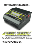
Figure 1.
Pictorial example of a quad-rotor; shown in an X-configuration
This project would require an agile aerial vehicle and the most suitable design would be
a multi-rotor vehicle well known to many hobbyists as a ‘quad copter’. It is a quad rotor
helicopter and therefore for simplicity the term quad-copter was adopted for use in the
rest of the project. The quad rotor in consideration here is a small agile, versatile multidirectional flying object with four rotating propellers (mounted on four electric motors)
arranged so that they are aligned in a squared x-formation, as shown in figure 1.
3
The design is nothing near in size like de Bothezat’s machine but it has been scaled
down to a few tenths of centimetres. The type of alignment use is x-type alignment or
x-configuration (meaning the alignment is squared and ’x’ shaped) as illustrated in appendix 1. Changing the alignment means the firmware must also change and will also
require making adjustments to motors connections, hence altering their direction of
rotation. The dynamics of the quad-rotor can be mathematically related to Euler and
Newtonian laws of motion of a rigid body. Together these laws better describe the
combined dynamics of translational and rotational motions of a rigid body.
2.2
2.2.1
GPS Fundamentals
Background and Introduction
The GPS is a satellite navigation system. GPS simply means global positioning system
(also known as NAVSTARGPS, that is, Navigation System with Timing and Ranging
Global Positioning System). It was developed by the U.S. (United States) Department
of Defence (DoD). There were as many as 24 fully operational satellites in 1994 that
completed the GPS space segment orbiting the earth at about 20,000 km above sea
level on six different orbital planes inclined at 55°. These satellites are constantly rotating completing the orbits twice in less than 24 hours at speeds roughly 11,300 km/h.
Most satellites (GPS satellites inclusive) are powered essentially by solar energy although there might be backup batteries on-board should in case there is a solar eclipse.
Figure 2 shows a pictographic illustration of how these satellites are positioned in orbit.
[1; 2; 3, 9-12].
There are many other systems in operation developed and used by other countries,
some of which might also have global coverage, such as Russia’s GLONASS (acronym
for ‘Globalnaya Navigatsionnaya Sputnikovaya Sistema’ or Global Navigation Satellite
System), the European Union's Galileo Positioning System which is also a GNSS
(Global Navigation Satellite System), and China’s global system called COMPASS navigation system also known as BeiDou Navigation Satellite System (BDS) [1; 4; 17, 40].
The first satellite system (also known as Transit) became operational in 1964 prior to
the introduction of the GPS. Consequently the first GPS satellite was launched in 1978
to be used for military purposes; however in 1984 the GPS would be made available for
4
civilian use too. The system constantly undergoes improvements whereby new, better
and more accurate satellites are being launched to replace older satellites. Modernisation efforts for the GPS III began in 2008 and the first upgraded satellites are expected
to go online by 2014. [5]
Figure 2.
A Diagram of the GPS Satellite Array or Constellation; Adapted from Garmin Ltd. [2]
It should be noted that the GPS satellite representation in figure 2 is used only as an
example to show the positioning of navigation satellites in orbit.
2.2.2
Devices, Concept and Application
The GPS (global Positioning System) would be incomplete without the user applications and GPS receivers. These are devices that enable users to receive signals from
the GPS satellites and use them for positioning, locating, navigating and surveying.
GPS receivers could be classified into five categories: consumer, military, mapping and
resource, commercial transportation and survey models. The C/A-code (Coarse Acquisition code) also known as SPS (Standard Positioning Service) refers to the signals
received by civilian and or other consumer GPS receivers. Conversely the Precision
code (P-code) also known as Precise Positioning Service (PPS) is resistant to jamming
and spoofing. Therefore it is used for military applications particularly by the U.S military. With this code, transmissions are encrypted and require specially enhanced receivers. [13, 54-56]
5
2.3
2.3.1
The SIM900 GPRS Module
GPRS/GSM Basics
The main function of the GPRS/GSM module is to send an alert with the corresponding
coordinates of the location of an impending disaster, accident, or event. If there is an
incident, depending on the type, nature and significance of the incident, specialised
sensors would be triggered accordingly. For example, a gas leak would trigger a gas
sensor and an earthquake would trigger an earthquake sensor. Signals reaching specified thresholds are then dispatched along with the GPS coordinates of the location, via
the GPRS system into the GSM network. Using AT Commands the GPRS device is
programed to send an SMS (Short Message Service) and is optimized for M2M telemetry. Important information could be transmitted or broadcast through the GSM network
to any mobile phone or to another appropriate device.
A simple SIM-card enhances the system’s communication range and gives it access to
the GSM mobile network. Figure 10 shows a SIM900-GPRS module programmable
with AT-commands and designed as a shield to fit on the Arduino Uno demo board.
The incorporation of the SIM900-GPRS module in the project is vital and also important
since it links the whole system to the GSM mobile network. Different forms and formats
of data or information would easily be broadcasted to every mobile phone in a given
area. Depending on what shows up in the surveillance information the ability to send
lifesaving preventive warnings to everyone is assured.
2.3.2
Technical information and Application
The SIM900-module is a Quad-band GSM/GPRS module is built on a single chip processor platform. The integrated AMR926EJ-S core is cost effective and its small size
offers an added advantage to users. [14] The SIM900-module also complies with the
GPRS standards in terms of interface and operations within the GSM/GPRS
850/900/1800/1900MHz frequency ranges. It is also optimized for voice and other
forms of data transfer including text and images. The module is 24 mm x 24 mm x 3
mm in dimensions, power consumption is low, and is designed to meet almost any requirements for M2M applications.[14]
6
2.3.3
SIM900 GPRS/GSM AT Commands
The definition of AT Command may vary but it is mostly defined as a machine code or
instructions that are used to activate features on a modem (in this case, the SIM900
GPRS/GSM module).
A series of machine instructions used to activate features on an intelligent modem. Developed by Hayes Microcomputer Products and officially known as the
Hayes Standard AT Command Set, it is used entirely or partially by most every
modem manufacturer. AT is a mnemonic code for ATtention, which is the prefix
that initiates each command to the modem. [20]
AT-Commands are sometimes classified as basic, S-parameter and extended however
all three categories differ syntactically. The basic command syntax is made up of a
command and an argument whereas the S parameter syntax involves a command, an
index to the S register and the value to be assigned to the register. As for extended
commands, they operate in several modes as, Test, Read, Write and Execution Commands. The syntax and example of such commands are illustrated in listing 1. It is important to note that all AT command lines must begin with the prefix AT and to end or
terminate a command line a carriage return (<CR>) is entered. The SIM900 AT Command manual explains in much greater detail how to use or implement these commands. Therefore explanations are limited to the scope of this project. [18, 2; 19, 1213].
Test command Syntax:
Example:
Read Command Syntax:
Example:
Write Command Syntax:
Example:
Execute Syntax:
Example:
Listing 1.
AT+<command>=?
AT+ATD=?
AT+<command>=?
AT+CBC?
AT+<command>=1st value, 2nd value, …,
Nth value
AT+CSCA=”+358468946311”, 120
AT+<command>=1st parameter, 2nd parameter, …, Nth parameter
AT+CMSS=1,”+358468946311”, 120
Syntax for Test, Read, Write and Execute AT-Commands. Adapted from Engineers
Garage [18, 2] and SIMCom [19,218-228]
These commands are essential in the programming of the SIM900 GPRS/GSM module
and are used in the project to send instructions and communicate with SIM900
GPRS/GSM module via the RS-232 or USB interface depending on the type or version
of the device used.
7
3
System Description and Design
3.1
3.1.1
Hardware Description and Design
Basic System Blocks
The flight control board or flight controller (FC), the Programmable System on Chip
(PSoC) chip controller board, the Autopilot board and the SIM900-GPRS module are
the hardware blocks. They are supported by gyroscopes and accelerometers on the
FC, the electronic compasses and GPS receivers connected to the PSoC, and the Arduino uno demo board running the GPRS shown in figure 10 below and figure 33 in
appendix 2.
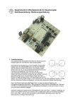
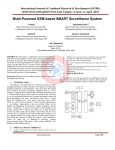
Figure 3.
A general block diagram of the Main System.
GPS receiver (uPatch100) captures a stream of data known as National Maritime Electronic Association (NMEA) sentences from a constellation of satellites that constitute
the space section of the GPS navigation system. For proper 3D-tracking about four
satellites are required but then a valid fix must be achieved. The process managing
8
program is the section of software that coordinates the signalling between the autopilot
and the FC. It also works with the flight control program that channel the GPS coordinates acquisition program with the autopilot and FC during navigation. Figure 3 also
shows a camera block which represents the surveillance camera and video transmitter
and the radio receiver that channels signals from transmitter to the autopilot and flight
controller.
3.1.2
Quad-copter Design and Mechanism
As mentioned in section 2.1, a quad-copter is a like a quad rotor helicopter with two of
its rotors rotating in the clockwise direction while the other two rotate in the counterclockwise direction. There are various techniques involved in the design of a quadcopter and whatever the design, be it simple, complex or sophisticated, the physics and
basic principles that make the object fly are the same. The quad-copter basically consists of four propellers mounted on four rotating motors therefore a simple design of a
mini-version of the object will require a sizable frame structure. The frame must be robust enough to handle all forces and vibrations subjected to it and also support the
weight of the motors and battery attached to it.
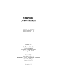
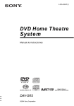
Figure 4.
A picture of the Quad-copter structure and other hardware including version 2.1 of
the HK Multi-Rotor Flight control board.
The wooden frame is flexible, tough and resilient, however not as strong as the more
expensive carbon fibre, which could also be used. Figure 4 shows the complete frame,
hardware and the flight control board mounted and optimized for x-configuration. Fig-
9
ures 24, 25, 26, 27 and 28 in appendix 1 show a model of the quad-copter, the simplicity of quad rotor design in terms of material and structure. The hardware is suitable in
architecture and electronics for many other types of vehicles, different in shape, alignment or type of configuration. The flight control board is marked to indicate where the
front of the craft and board orientation defers with type of configuration, selectable from
the flight control board programming display menu. Building everything from scratch
would have meant using a Computerized Numerically Controlled (CNC) router to machine all the parts. For simplicity, it was preferable to build the quad-copter part-by-part
including brushless motors and propellers, as can be seen in appendix 1.
The type of motors used was Turnigy L2210-1400 Bell, with voltage specification;
7.4~11.1 volts powered by 3-cell-LiPo battery. The motors have speed specification of
1400 rpm/v, a current on no load of 1.1 amperes, max current of 24A and a maximum
power of 210 Watts. The motor is relatively lightweight about 50 grams, a 3 mm shaft
size, 28 mm shaft length, motor size of 28 mm x 17 mm and can deliver a thrust of 880
grams. The main body frame was bought in pieces as a kit and then the quad-copter
was built by assembling and gluing the prefabricated pieces (shown in appendix 1)
together to form a strong wooden frame as in figure 4. The flight control board also
comes as a complete module with sensors processor and preinstalled firmware; all that
is left to do is to connect the motors, radio receiver and autopilot [15].
3.1.3
Flight Control Board
The flight control board is a unit whose purpose is to stabilize the quad-copter while in
flight. It provides the ability to connect a radio receiver, allowing for manual control and
also a possible attachment of an autopilot for autonomous navigation. Onboard inertial
sensors or gyroscopes and accelerometers are used to detect signals generated as a
result of the various degrees of movement of the vehicle on which the flight control
board is mounted. The HK-Multi-rotor Flight Controller Version 2.1 board has three of
such gyroscopes mounted, so that they operate at right-angle to each other, in the x, y
and z axes orientation respectively in a three dimensional space as shown in figure 5.
The gyroscope senses and passes roll, pitch and yaw motion signals to an Atmega168PA processor [21].
Most flight control boards are programmable or can be flashed with the Firmware provided by the manufacturer. In some cases the user can also upload customized soft-
10
ware to the onboard processor using a specialized 6-pin USBasp AVR Programmer.
Another flight control board or flight controller, the KK2.0 Multi-rotor Flight Control
shown in figure 6 has much more flexibility, more advanced functions and has a Liquid
Crystal Display (LCD) which makes it easier to use. The flight controller feeds signals
to the Electronic Speed Controllers (ESCs) which in turn control the angular velocity or
rotational speed of the motors thereby changing the flight dynamics of the quad-copter.
Unlike the previously mentioned HK-Multi-rotor Flight Control Version 2.1 board (where
HK is an abbreviation of HobbyKing), the KK2.0 Flight Controller is equipped with an
Atmega324PA processor. [22; 21]
Figure 5.
Three dimensional array of Murata-type Piezoelectric Gyroscope sensor modules
as mounted on HK-Multi-rotor Flight control board version 2.1.
Signals from the radio receiver (Rx-Receiver) are fed into the processor via four input
connectors on the flight control board. These inputs are labeled aileron, elevator, throttle and rudder (sometimes abridged as Ail, Ele, Thr and Rud), are Pulse Width Modulated (PWM) signals. The signals’ pulse widths drive the Electronic Speed Controllers
which control the speeds of each motor and initiate an up or down, a forward or backward and or a left or right motion of the quad-copter [22; 21]. The full mechanism of
motion of the quad-copter will be discussed subsequently in section 3, under the hardware description and analysis.
The KK2.0 flight controller has two built-in 3-axis single-chip gyroscopes and a singlechip 3-axis accelerometer system simultaneously, giving it an increase in stability and
11
the added advantage of having an auto-leveling functionality. This function requires
that the sensors be properly calibrated and the vehicle must be sitting on a leveled
plane surface. Also in the auto-level settings, the P-gains and I-gains must be set so as
to maintain some degree of control over the quad-copter during flights. The additional
onboard LCD screen and built-in firmware or preinstalled software allows for an easy
setup. Most functions, that is, the Craft type selection, the motor layout and direction of
rotation, ESC calibrations, radio receiver test, sensor test, roll, pitch and yaw gains, PI
editor, sensor calibration, mixer editor and more functions, are set with just a simple
click of buttons, selections from a menu and following the onscreen prompts [21; 22].
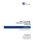
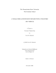
Figure 6.
KK2.0 Multi-rotor LCD Flight Control Board. Adapted from HobbyKing [22]
As can be seen from figure 6 above, there are up to five receiver input channels and
eight motor output channels. The fifth input channel is reserved for auxiliary functions,
while the extra four motor output (not used in this project) are reserved for use in other
types of multi rotor vehicles with more than four rotors.
3.1.4
Sensors Features and Characteristics
As earlier discussed, there are two main types of sensors used to maintain balance
and stabilisation when the quad-rotor is in flight. These sensors include the gyroscope
and the accelerometer. The HK-Flight Control Version 2.1 board integrates only three
single axis gyroscopes whereas the more advanced HK-KK2.0-Multi-rotor Flight control
board has both two 3-axis gyroscopes and one 3-axis accelerometers. The former uses
12
three Murata analogue piezoelectric gyros while the latter uses single chip 3-axes InvenSense MEMS technology type gyroscopes and the advanced Analog Device accelerometers. Figure 7 shows a detailed circuit diagram of a Murata ENC03-MB analogue
gyroscope.
Figure 7.
ENC03-MB Sensor (single axis gyroscope) Adapted from Murata Manufacturing
[6,1-3]
The ENC03-MB Sensor (gyroscope) is used to sense gyroscopic or angular movements of the quad-copter on the x, y and z-axes. This gyroscope is miniaturised ultralightweight angular rate sensor whose operation principle is based on the Coriolis force
effect. This phenomenon (the Coriolis Force Effect) is triggered when an angular rate
causes vibrations in the sensor. These vibrational changes are converted into electrical
impulses which are amplified and sent to the output pin on the sensor’s break-out
board ready for processing. [3, 1-2].
Figure 8.
ITG-3200 Integrated Triple-Axis Digital-Output Gyroscope Block Diagram and chip.
Adapted from InvenSense Product catalogue [23]
Alternatively to the Murata analogue piezoelectric gyroscope, the InvenSense MEMS
single-chip 3–axis gyroscope such as the ITG-3200 in figure 9, integrates MEMS and
13
CMOS technology through wafer-level bonding. It is an x, y, and z-axis ultra-sensitive
(14 LSBs per °/sec) digital-output angular rate sensor, miniaturized into a single tiny
chip with an I²C (400 kHz) serial interface. Having multiple gyroscopes certainly allows
for more flexibility and a much greater degree of freedom of movement and control. In
addition to two gyroscopes the flight controller has a 3-axis accelerometer on-board.
The ADXL377 is a 3-axis high g Analogue MEMS Accelerometer which is also a good
example of an Analog Device Inc. accelerometer. It provides analogue output voltage
signal proportional to acceleration. It is capable of measuring static acceleration of
gravity in tilt-sensing and dynamic acceleration (acceleration resulting from motion,
shock, or vibration) applications. [25, 1; 25, 5-7].
Figure 9.
Functional Block Diagram for ADXL377 3-Axis High g Analog MEMS Accelerometer
and Output linearity over the Dynamic range. (Copied from Analog Device
ADXL377 Datasheet. [25, 1-5]
The ADXL377 accelerometer senses ±200g full-scale range, with low power (at ~300
µA and 1.8 to 3.6V), it has a shock resistance of up to 10000g and it is a user adjustable bandwidth accelerometer [25, 5-7]. The half power bandwidth of which is given by:
⁄
Simplified as:
⁄
Where
is the half power bandwidth, 32kΩ is the nominal value (±15%) of the
internal resistor RFILT, and
pacitance of 1000pF. [25, 5-7].
are recommended to have a minimum ca-
14
3.1.5
SIM900 GPRS Module
The General Packet Radio Service (GPRS) refers to the standard overseeing wireless
communications having working speeds of up to 115 kbps. The service includes a significant range of bandwidths efficient for sending and receiving data appropriately.
Such data could be in form of Web browsing and or messaging, Instant Messaging
(IM), electronic mail (e-mail), SMS or Multimedia Messaging (MMS) and possibly other
forms of data.
Figure 10. Snapshots of the SIM900-GPRS shield, showing the bottom and top views with its
main features.
The GPRS module chosen for this project has the required characteristic and incorporates a SIM900 on a Printed Circuit board (PCB) to form a GPSR shield as shown in
figure 10. The device was made by SIMCom as a complete Quad-band GSM/GPRS
module designed on a single-chip processor integrating AMR926EJ-S core. It is reliable and has the following general characteristics which are also specific to what the
project requires: [14; 16]
-
Quad-Band 850/ 900/ 1800/ 1900 MHz
GPRS multi-slot class 10/8
GPRS mobile station class B
Compliant to GSM phase 2/2+
Class 4 (2 W @850/ 900 MHz)
Class 1 (1 W @ 1800/1900MHz)
Dimensions: 24*24*3mm
15
-
Weight: 3.4g
Control via AT commands (GSM 07.07 ,07.05 and SIMCOM enhanced AT
Commands)
SIM application toolkit
Supply voltage range : 3.2 ... 4.8V
Low power consumption: 1.0mA(sleep mode)
Operation temperature: -40°C to +85°C
[14;16]
These characteristics are the bases for which the module was chosen. There are many
more features functions and advanced characteristic of the SIM900-GPRS that are
beyond the scope of this project.
3.1.6
GPS Receiver
Retrieving data from the satellites requires an appropriate GPS receiver that is sizable
and easy to interface with a microcontroller. The uPatch100 is a 28 x 28 x 7.0 mm ([W
x L x H] the antenna inclusive) device built on a Sony chip set CXA3355 RF and
CXD2956 Baseband high performance architecture. The module has two regulated
3.3V to 5.5V supplies, an 8-pin external connection, described in table 1, and one Universal Asynchronous Receiver Transmitter (UART) port that can be preconfigured for
4800 or 9600 bps and for RS232 or CMOS signal levels. Devices of the type
uPatch100-R4 are configured for RS232 level at 4800 bps while uPatch100-C4 is for
CMOS level at 4800 bps or bps.
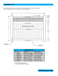
Table 1.
Input/output Pins on uPatch100 GPS receiver module. Adapted from Fastrax Ltd.
Technical Interface Description uPatch100 GPS Receiver [8]
Pin
1
2
3
4
5
6
7
8
Signal
VDD
TxD0
RxD0
GND
XRESET
VBAT
1PPS
GPIO9
Input/output
Power
Output
Input
Ground
Input
Power
Output
Output
Description
+3.3V to +5.5V Main power
UART Transmit Data, RS232 or CMOS level
UART Receive Data, RS232 or CMOS level
Power and Signal ground
No connection
Power +3.3V to +5.5V Backup Battery Power.
1 Pulse Per Second Output, CMOS level 2
Satellite Fix indicator output, CMOS level 2
Eight different NMEA sentences are possible with the uPatch100 four of which are
shown in figure 11. However the output can be customized using @NC SONY ASCII
protocol command. The upatch100-C4 (picture and block diagram, shown in figure 12),
operates at 4800 bps and outputs four NMEA-0183 V3.0 sentences, indicated by the
16
headers GPGGA, GPGSA, GPGSV and GPRMC as in figure 11, was chosen for its
simplicity and ease of use and interfacing properties that would hence render its implementation in the project less complex. [7].
Figure 11. The uPatch100-C4 TxD0 raw output (no GPS data); Screenshot and TxD0 (blue)
and 1PPS (Red) waveform as seen on the oscilloscope.
VBAT provides power to enable the receiver to store the almanac and the ephemeris
data. The almanac data comprises constant transmissions of approximate positions of
the satellites whereas the ephemeris data contains the precise positions of the satellites. Without VBAT the receiver’s memory is erased each time the main power VDD is
turned off [7; 8; 13, 56].
The antenna for the GPS receiver is characterised by its operation on a 28x28 mm
ground plane, meaning the uPatch100-C4 patch antenna is tuned at 3 MHz above the
centre frequency of 1575 MHz to 1578 MHz, hence countering any effects that may
result from the (usually plastic) casing. The asynchronous (UART) serial communica-
17
tion port is 4800 bps at 3.0V CMOS level signal, no parity, eight data bits and 1 stop
bit with an xxx,N,8,1, data format. As shown in figure 11, the uPatch100-C4 TxD0 terminal (also shown in the bock diagram, figure 12) will output a burst of signals every
second, which means all four NMEA sentences are sent within a span of a second or
every 1PPS pulse. The waveform of the 1PPS signal compared with the TxD0 can be
seen in appendix 4.
Figure 12. Picture of the top and bottom view of the uPatch100-C4 GPS receiver module and
block diagram (right). Adapted from Fastrax uPatch100 Technical Interface Description ver. 3.2 [8, 7]
In applications where more NMEA-sentences are required, the uPatch100 is limited
and simply updating the firmware might not help. However there are newer versions of
GPS receivers of the same series which are capable of outputing more sentences.
3.1.7
Aerial Surveillance System
Surveillance cameras vary in type, shape, size and function and there are a wide variety of tiny, micro or mini cameras and there are many others commercially available. It is
expected that the quad-copter may attain an average height of 30 meters since the
altitude (antenna height from sea level) is retrieved from the GPS data. It will therefore
be required that the surveillance camera be robust enough to withstand vibrations,
18
shock and acquire clear images at high altitudes. There are however a few other specifications with which the camera must comply. That is, it must be a wireless camera,
lightweight, small in size and powered by a supply of about 5 volts with a good resolution. The First Person View (FPV) cameras associated with many hobbyists and RCplane enthusiasts are best suitable for projects such as this. Nevertheless a more practical and less expensive solution was found. Figure 13 shows a snapshot photo of a 2.4
GHz Wireless Pinhole Camera with a built-in Li-Battery, a 62 degree view and DC 5
volts 80mA input for power and battery charging. The charge and power are selectable
by slide switch. The camera poses a CMOS sensor optimized for PAL/NTSC systems
with a resolution 628x582 (PAL) and 510x452 (NTSC). The minimum illumination is 1.5
Lux/F1.5, and the gain control is automatic with transmission frequency and a power of
ISM 2400 MHz-2483 MHz and 10 mW respectively.
Figure 13. Multiple views Snapshots of a 2.4GHz Wireless Pinhole surveillance Camera.
To complete the surveillance system a proper unit is needed to capture the video
transmitted from the wireless camera. It is required that the unit be a wireless unit
which can be connected to the universal serial bus interface. The wireless Universal
Serial Bus Digital Video Recorder (Wireless USB DVR) is a suitable choice and has the
required characteristics. Figure 14 shows a wireless USB DVR, model ES-601WS, a
wireless audio-visual USB DVR receiver with an operating frequency of up to 2.4 GHz,
4-channel input recording, 30 frames per second images capture and AVI file format
compatible with Windows Media Player. The device is USB 2.0 compatible with an in-
19
terface transmission rate of 480 Mbps, an image resolution of 720*576 or 1440*1152
pixels for a moving image, automatic brightness adjustment functionality and other advanced digital video control functions [26,1-2]. A sample of the video image transmitted
from the wireless camera and received by the ES-601WS wireless USB DVR, which is
also shown in figure 23. The Eye Sight Technology application software is called MultiViewer. The MultiViewer is a 4-Channel surveillance software compatible with Windows, having Joint Photographic Experts Group (JPEG) image format, snapshot-fromvideo function and can be configured to attach and email images to a specified address
[26, 1-5].
Figure 14.
A wireless USB DVR. Adapted from Eye Sight Technology Co., Ltd. [26, 1-5].
The wireless USB DVR adapter will work on any computer provides the right drivers
and the application software are installed.
3.1.8
Autopilot Design
The base of the autopilot hardware is the Programmable System on Chip (PSoC)
board and CY8C29466PXI microchip controller unit. The PSoC chip is based on a
powerful Harvard Architecture, 24 MHz, 32-bit accumulator, and a low-powered high
speed M8C-core processor. With a relatively low operation voltage range of 4.75 to
5.25 V, the CY8C29466-24PXI PSoC unit can work at extended temperatures ranging
from -40°C to +125°C. The MCU is mounted on a PSoC board as shown in figure 15.
The chip has 12 rail-to-rail analogue blocks of 14-bit Analogue-to-Digital Converters
20
(ADCs), 9-bit Digital-to-Analogue Converters (DACs) and a variety of Programmable
Gain Amplifiers (PGAs). The PSoC MCU is very advanced. Programmable filters and
comparators complement the analogue blocks with 16 digital blocks supplying 8- to 32Bit timers, counters, and Pulse Width Modulators (PWMs), Cyclical Redundancy Check
(CRC) and Pseudo Random Sequence (PRS) modules and up to four full-duplex or
eight half-duplex Universal Asynchronous Receiver Transmitters (UARTs) and multiple
SPI masters or slaves [9, 1].
Figure 15. Picture of a PSoC Board and its features.
All features and blocks described are built in on a single Integrated circuit (IC) and
connectable to all intrinsic Global input/output peripherals (GPIO) and also to external
ports on the PSoC board [9, 1]. It is possible to build complex peripherals just by combining different blocks together. This can be done in the chip level configuration of the
PSoC designer application software, where various modules such as timers, PWMs,
UARTs, and PGAs can be placed just with a simple drag and drop gesture, and interconnected with a click of the mouse button. [9, 1-8].
A customized Autopilot Control board specially designed for the purpose of carrying out
this project is shown in figure 16. The board was carefully designed to fit on the PSoC
evaluation board like a shield, as illustrated in appendix 2, so that the CY8C2946624PXI chip controller IC on the board connects in an appropriate manner with the components on the autopilot shield. The chip is encased in a 28-pin integrated circuit DIP
package with the ability to connect to three output ports, that is, Port 0 (P0), port 1 (P1)
and port 2 (P2). P2 has a 14-pin connector to which the Liquid Crystal Display (LDC)
21
can be connected. These ports are also shown on the autopilot shield or board. P0 and
P1 are 10-pin ports, eight pins are for data and two are for powering externally connected components. Port 2 is reserved for LCD connection by default. However some
pins on P0 have been modified for use as connectors to the motors and could be used
for this purpose as well.
Figure 16. Autopilot control board and its features.
The characteristics of the C29466-24PXI chip controller are optimum, therefore making
it a suitable choice for this project. All required modules are in one chip and versatility
is guaranteed, which is also important for autopilot functionality. Signals from the radio
receiver are interfaced with each of the internal blocks, these control signals can then
be processed and controlled by the PSoC ImageCraft-C software. Every one of the
different signals from the receiver is captured by a timer module in the chip level configuration shown in figure 18. A timed interrupt is generated each time there is a
change in the level of the incoming pulse from the receiver. Based on this time the
pulse width is calculated. The calculated pulse width is then written into the PWM
which in turn outputs a pulse with the same characteristics as the input pulse. In doing
so the autopilot program has control over the quad-copter since it can channel signals
from the receiver to the flight controller in the manual mode and also send control signals to the controller, in the auto-navigation mode.
22
3.2
Software Description, Design and Implementation
3.2.1
Acquiring GPS NMEA-sentences for Information
As discussed in section 3.1.6, when powered the upatch100 GPS receiver module outputs a burst of data every second as a series of character strings called the NMEA
Sentences, as illustrated in figure 11 and figure 22. Once the required sentence has
been captured, it is stored in a buffer. Every NMEA sentence begins with a $ sign, so
as listing 1 shows, the if(UART_cGetChar()=='$') line looks for the beginning of the
sentence string denoted by the dollar sign. However the program will miss that character and start storing from the second character. Thus the buffer is initialized so that the
first element in it is always a $ sign, to maintain the starting character of each sentence; in doing so, the program will always know where a sentence begins.
void readGPS_Nmea(void)
if(UART_cGetChar()=='$'){
Buffer[0]='$';
i=1;
while (Flag) {
Buffer[i]=UART_cGetChar();
Delay50uTimes(10);
if(Buffer[i]=='$'&&i>0) Flag=0;
else i++;
}
UART_CPutString("\r\nBuffer: ");
UART_PutString(Buffer);
}
}
Listing 2.
A piece code for getting data from the GPS sensor module (upatch100-C4)
Now that the buffer already contains ‘$’ at index zero, the index is reinitialized to one
and the rest of the characters in the sentence are indexed into the buffer until the beginning of the next sentence. At this point the content of the buffer is similar to the following format:
-
$GPRMC,hhmmss,A,llll.ll,a,yyyyy.yy,a,x.x,x.x,ddmmyy,x.x,a*hh
Where GPRMC is the header representing the sentence type or sentence identifier that
always follows the $ character, as in the following example of a complete sentence with
information:
-
$GPRMC,152741,A,6012.4688,N,02439.7964,E,000.0,000.0,281212,,,A*79
The full description of the information in the sentence has been given in table 2. There
are other sentences from which data can be extracted; however the GPRMC is a good
23
example for demonstration of the process. It can be seen from table 2 that the GPRMC
identifier contains information about the time, latitude, longitude, ground speed, magnetic variation and the date. The date is current whereas the time is the Universal Time
Coordinate and if need be the actual time in the location of use must be calculated accordingly.
Table 2.
Full description of the GPRMC sentence
Data
segment Format
$GPRMC
Example
of
data segment
$GPRMC
HHMMSS
A
llll.ll,a
yyyyy.yy,a
x.x
x.x
ddmmyy
x.x,a
152741
A
6012.4688,N
02439.7964,E
000.0
000.0
281212
,,,
*hh
*79
Name
Description
Sentence
identifier
Time (UTC)
validity
Latitude
Longitude
Speed in knots
True course
Date
Variation
in degrees
checksum
Recommended minimum
specific GPS / Transit data
15:27:41 Universal Time Coordinate (UTC)
validity , A=ok, V=invalid or warning
60 12.4688’ N
24 39.7964’ E
Speed over ground in Knots
Heading with-respect-to true North
th
28 December 2012 (28-12-2012)
Magnetic variations in degrees
For checking transmission errors
It should be noted that other sentences can be analysed and described in a similar
manner as the GPRMC, described in table 2 above.
3.2.2
Parsing Data from NMEA-Sentence
In section 3.2.1 with reference to listing 2 there was an analysis of procedure for storing
the required sentence into the buffer; thus, the content of the buffer must be parsed to
retrieve the information from the string of data in it. Listing 3 shows a section of code
responsible for the parsing process, whereby the content of the buffer is parsed using
the string tokenizing function strtok(). Since each informative parameter in the NMEA
sentence (which itself begins with $) is separated from the other by a comma, the tokenizing function uses the ‘$’ and ‘,’ characters as delimiters. The switch-case structure
of the program selectively stores each parameter in the appropriate variable.
After all the selection and parsing is done, the result will be; header GPRMC (sentence
identifier) while data0 to data9 152741 (UTC time 15:27:41), A (validity indicator),
6012.4688N (Latitude 60 degrees 12.4688 minutes North), 02439.7964E (Longitude 24
degrees 39.7964 East), 000.0 knots (speed in knots), 000.0 (true course), 281212
24
(date 28-12-2012), respectively in that order. Now that information has been extracted
it is stored and used according to the demand by the autopilot. The autopilot program
constantly updates the GPS information.
cTok = strtok(Buffer, delim);
while (cTok != NULL){
switch (comma) {
case 0: header = cTok; break;
case 1: data0 = cTok; break;
case 2: data1 = cTok; break;
case 3: data2 = cTok; break;
.
.
.
case 10: data9 = cTok; break;
}
comma++;
cTok = strtok(NULL, delim);
Delay50uTimes(10);
}
Listing 3.
A section of code required to parse the NMEA sentence string store in the buffer
The GPS data is stored in string format. Thus in order for the program to be able to use
these data the functions itoa() and ftoa() are used to convert the string to an integer
and float respectively. In this format the program is able to use the values to carry out
the required calculations.
3.2.3
Activating the Sim900 GPSR/GSM Communication
The sim900 is activated using AT commands once the SIM card has been inserted. It is
also recommended to use the default pin-code during testing if it is not deactivated.
When all is set the procedure for setting the SMS mode is as follows:
AT<CR>
// initiates ‘Attention’
AT+CPIN=1234<CR>
// enters the pin code
AT+CMGF=1<CR>
// set the SIM900 to SMS (text) mode
AT+CMGS="+358xxxxxxxxx"<CR>
// Enters the destination phone
number
> “message to be sent here.” <Ctrl+z>
// pess control+z after message
Listing 4.
AT command syntaxes for sending SMS to a specific phone number.
The commands in listing 4 above are inserted into a C-language code as a string of
characters which are then sent to the SIM900 via a terminal program. Alternatively, the
commands could be defined within a C-language code to be actuated at specific mo-
25
ments. The code would then be simply compiled and uploaded into the Arduino/GPRS
shield unit. For the purpose of this project the SMS message to be sent will be specific
GPS coordinates that would be preprogramed in the software.
3.2.4
Acquiring Heading and Calculating Bearing
The Heading is acquired by reading the electronic compass or by getting course-madetrue value from the GPS receiver. Calculating the bearing of the destination requires
the GPS coordinates of the origin or current position and the destination coordinates.
Then the two-point coordinate technique is used to calculate the angle between the line
through the points (OB) and the vertical line through the origin (OA, or with respect to
the North); which is the bearing. Considering figure 17, the origin of the graph is
but the flight starts at point ‘O’ and the destination is at point ‘B’, the distances OB, OA
and OC (considering a flat surface) are given by the equations;
√
√
√
(1)
(2)
(3)
Equations 1, 2 and 3 are formulated based on the geometry of Cartesian coordinate,
since the coordinates used are latitudes and longitudes.
Figure 17. Graphical illustration for calculations involving bearing and distance using two-point
coordinates.
The tangent of the angle α is the length of the opposite side OC or AB divided by that
of the adjacent side OA. The bearing is then calculated by taking the arctangent of the
26
result [24]. The same formula would apply if the coordinate were replaced with latitudes
and longitudes from the GPS data. The latitudes will replace the x-coordinates, while
the longitudes will replace the y-coordinates. Considering equations (1), (2) and (3)
were for calculations on a flat surface; however the earth’s surface is spherical, so a
more accurate calculation of the distance OA, OB and OC, that takes into consideration
the curved surface or spherical nature of the earth is given by:
{√
(
)
(
)}
In terms of latitude (lat) and longitude (lon);
{√
(
)
(
)}
(4)
The value of R is the radius of the earth about 6,371 kilometres and equation (4) is a
derivative of the Haversine formula.
Following from equations (2) and (3), the bearing is then calculated from the distances as follows;
⁄
Where b is the bearing in degrees (α t0 the vertical); the great-circle cosine approach will be:
{
3.2.5
}
Software Management of Navigation and Control
The operation of hardware such as the GPS receiver, Magnetometer and other autopilot functionalities are managed by the software. The software design is created in the
chip level configuration section of the PSoC designer program as figure 18 illustrates.
There three main types of functional blocks in the chip level configuration, the 16-bit
Timer, 8-bit PWM and UART. The UART block, connects to the GPS receiver and provides an interface between the GPS receiver and the PSoC program ensuring its ability
to monitor, retrieve, organize and use the GPS data. Each timer block connects to a
channel on the radio receiver and provides the means by which signals from the receiver are channelled through the autopilot to the flight controller. The timer uses the
PSoC timer interrupt and time capture functionality to measure the pulse width of the
27
signals for the radio receiver. The time capture function is demonstrated by listing 5.
The software checks the status of a flag while it compares the time difference between
the rising edge and the falling edge of the pulse.
Figure 18. Screenshot of the chip level configuration of project software. Created with PSoC
Designer [29].
Since the signals are pulse width modulated signals, an interrupt is triggered on every
rising edge of and stopped on the falling edge. The period is then used to calculate the
pulse width. These calculations are done internally in the autopilot program giving it
considerable control over the pulse width and hence the speed of the motors and
amount of thrust. There are four timer blocks each connected to a corresponding receiver channel from channel 1 (CH1) to channel 2 (CH2) respectively. The PWM block
28
channels the signals from the receiver to the flight controller in a controlled manner as
the autopilot program would allow. In the manual mode, the autopilot would feed the
pulse width of the receiver signal directly into the PWM which will in turn generate an
identical signal to be fed into the flight controller.
if(Flag1 & FALLING_EDGE_1)
{
CaptureNegEdge_1 = Timer16_CH1_wReadCompareValue();
Timer16_CH1_FUNC_LSB_REG &= ~0x80;
Flag1 &= ~FALLING_EDGE_1;
PulseWidth_1 = CapturePosEdge_1 - CaptureNegEdge_1;
Flag1 |= DATA_AVAILABLE_1;
}
Listing 5.
Section of code demonstrating the timer interrupt calculation of pulse width of an
input signal from the radio receiver.
On the other hand, the autopilot program causes the PWM to generate signals that
would be fed into the flight controller which then controls the flight of the quad-copter.
There are four PWM blocks that connect to four inputs on the flight controller: the aileron, elevator, throttle and rudder.
Figure 19. Diagram of a 6-channel 2GHz RC-transmitter (left) and receiver (right).
The radio transmitter stick controller has two control sticks that control two channels
each. These sticks can move vertically (up and down; covering one channel) and horizontally (left and right; covering the other channel) as shown in figure 19. The left stick
controls channels three and four (CH3 and CH4), while the right stick controls CH1 and
CH2. The stick controller plays an important role during manual operations; it is used to
29
steer the quad-copter, to move left or right, up or down and speedup or slowdown by
moving the sticks. The left stick is particularly important as the rudder channel CH4 is
also used to arm the flight control board.
3.2.6
Programming the Autopilot and Flight Control
The autopilot is the unit that takes control and manages the flight and control of the
quad-copter when manual operations are switched off. First the 2.4GHz, FM modulated
RC-Transmitter (shown in figure 19 with the receiver) is programmed in such a way
that one of the switch channels (CH5 or CH6) is used for switching the manual operations ON or OFF. Most transmitters come with user manuals from the manufacturer
with detailed but simple steps for programming user customized functions; however the
receiver requires no programming at all. The procedure is basically to assign specific
functions to the channels (CHX) on the transmitter, for example, CH4 could be assigned to Rudder, CH3 to the Throttle, CH2 assigned to the Elevator and CH1 to Aileron. After programming customized functions into the transmitter, it is ready to control
the quad-copter and switch between manual and autopilot functionality.
In order to carry out the necessary controls for flight and navigation, the autopilot must
be able to communicate with the four rotors that provide the trust and hence the lift. For
this reason the autopilot is connected to the flight control board and the radio receiver
will then be connected via the autopilot to the flight control board or flight controller
(FC). Each channel is plugged into the FC in their respective corresponding sockets;
then signals would be received from the transmitter or directly from the autopilot with
relative ease.
3.3
3.3.1
Analysis of Main Subsystem Operation
Quad-copter Flight Dynamics
In order to fully describe the flight dynamics of a quad rotor, much more complex analysis of various mathematical models would have to be considered, however a simpler
way to describe it will be in terms of rotor dynamics. This means that, almost every
movement would be associated with the rotation of the motors or rotors. If all four rotors rotate with the same speed, the quad-copter hovers, and increasing the speed on
30
each rotor causes the quad-copter to fly vertically upwards. In contrast, any slight increase or decrease in the rotational speed of any one of the rotors will change the dynamics. As figure 20 shows, the speed of the rotors is one of the determining factors in
which direction or how the quad-copter flies.
Figure 20. Quad rotor flight mechanism and dynamics based in x-type alignment or configuration.
As figure 20 illustrates, an increase in the speed of rotors 1 and 4 slightly above hover
creates a moment that results in the quad-copter moving to the right. Likewise increasing the speed of rotors 2 and 3 creates a left roll that results in the quad-copter moving
to the left. To achieve a clockwise or right yaw motion, the two adjacent clockwise rotating motors (1 and 3) speeds are slightly increased above hover speed. A left yaw
counter clockwise rotation is effected by an increase in speed of rotors 2 and 4, this
way various degrees of movements can be realized. The total vertical thrust on the
quad-copter is given as the sum of all individual thrusts on the rotors. Therefore,
The total torque is algebraic sum of the torques on each rotor, expressed as;
The moment due to a force on a body is defined as the product of the force and the
perpendicular distance from the turning point to the point on the line of the application
of the force. Therefore the moment due to each rotor is given by,
31
{
}
{
}
{
}
{
}
The blade or rotor speed at hover is given by [27, 30];
√ ⁄
The rotational speed or rotor angular velocity is given by;
where v, is the linear velocity and r is the radius of rotation.
The acceleration is calculated as follows; for linear acceleration,
which implies the angular acceleration is given by:
Therefore the torque which is related to the angular acceleration is given by:
Where I is the moment of inertia; considered the moment of a moment.
The lift is given by:
where L is lift in Newton (N),
is the lift coefficient, ρ is the density of the fluid
3
medium in kg/m , v is velocity due to the fluid medium in m/s and A is the area of
2
the body given in m .
3.3.2
Role of Software in Navigation
The software controls almost every aspect of the autopilot’s functionality, from the acquisition of GPS data to processing the data, calculate distances and bearing and also
control the quad-copter when operating in Autopilot mode. A description of the process
of acquiring and processing the NMEA sentence from the GPS receiver, in relation to
the role of the software in navigation is demonstrated by the flow chart in figure 21.
After checking the validity of the data the latitude and longitude are extracted, as discussed in section 3.2.2, the coordinates are used to calculate the distance to the location. First the destination coordinates must be predefined, then the systems starts the
course calculation program subroutine. This subroutine checks that the coordinate
have been acquired, it will then proceed to calculate the bearing and set a course. To
set the course, the system yaws to a specific angle to a reference plane (usually the
north) which is the bearing. The distance to location is constantly checked by processing information of the current position coordinates with respect to the destination.
32
Since the bearing and distance to location has been calculated and a course set, the
autopilot program starts the navigation subroutine. Considering figure 17, OABCO form
a rectangle whose sides represent the bounds within which the quad copter must navigate. The function of the navigation subroutine is to keep the quad copter within these
bounds. To do that it must constantly calculate new bounds, as the quad copter approaches the destination, the navigation bounds reduce in dimension too. The current
location become the new origin and the area of the rectangle OABCO reduces, the
distance proximity to the axes, lines OA and OC must decrease progressively at the
same pace. If the distance OA is significantly shorter than OC the system will pitch to
compensate and vice versa, keeping the quad copter on the course OB till the destination when all dimensions converge to zero distance.
Start
GPS
Receiver Data
Valid Data
Received?
NO
NMEA
Sentence
found?
Start
navigation
Get Destination
Coordinates And
Calculate current
coordinates
Adjust pitch and
Yaw to heading
NO
NO
bearing acquired
Course Set?
Coordinates
OK?
YES
All Data
Processed?
YES
Start
Course calculation
NO
YES
Parse NMEA
sentence
YES
YES
Process data
Start
Course calculation
NO
Calculate bearing
Current == NO and Set a course
Destination?
And Start
navigation
YES
NO
distance
to destination and
proximity to
axes OK?
YES
Stop!
Destination
Reached
Distance ==0
Maintain
Heading or course to
destination
Done
Start GPS
Figure 21. Diagram of a flowchart demonstrating the role of software in the navigation process.
The motors are controlled by pulses from the pulse width modulator (PWM) blocks in
the chip configuration of the PSoC designer, in conjunction with the program to determine when and how long a pulse should be sent to the flight controller. The flight controller’s firmware then manages the flight and stabilises the system using data from the
sensors and signals from the PWM, thus giving the autopilot a smooth functionality.
The rest of the raw code for the entire program is listed in listing 6 in appendix 3.
33
4
4.1
Results
System Guidance and Coordination
The system is said to be GPS guided, as a result it must be able to acquire GPS information with relative ease. Figure 22 shows a copy of the resulting NMEA sentence and
GPS information from the output of the GPS receiver. The information is in the form of
a string, so in order to use the information the system was designed to be able to select
the appropriate sentence identifier and retrieve the necessary information. Each sentence identifier is slightly different from the other and may not contain all the information needed; however the system was programmed to select all identifiers of sentences that contain longitude, latitude, altitude, heading, time, speed and date, which
are essential for guiding the quad-copter.
Figure 22. Sample of raw data from the GPS device showing all four NMEA sentences and
their data content
The quad-copter was designed and configured to eliminate any complications associated with the mechanical transmissions applied in the rotor-head cyclic and collective
pitch change control systems. Despite being more gust-sensitive, the quad-copter uses
a more complex harmonised rotor speed control and systematic thrust adjustments on
each of the four rotors to achieve lift, stirring and manoeuvring. Several tests, crashes
34
and readjustments were made to get the system working. At first it was difficult to get
the autopilot to take control and there was too much shaking. One of the motors
seemed unbalanced and there was no sense the system was actually following the
GPS data despite the valid fix indicator being on. There was a limitation in the PSoC
chip in that there was not enough space in the chip level configuration for the placing of
the number of blocks needed for the system. However a workaround was found by
using 8-bit PWM blocks rather that 16-bit block which require more space. Also if the
weather is windy, more power was required to stabilize the system and the risk of
crashing increases. Thus it would be recommended to fly the quad-copter under relatively favourable atmospheric conditions, especially when operating in the autopilot
mode. [27, 40]
The hardware setup is a step-by-step procedure that begins with settings on the flight
controller (FC) to the calibration. The flight controller’s function menu made setup easier; thus sensor calibration for gyros and accelerometers, stick scaling for the transmitter radio controller, pitch, roll and yaw gains, ESC calibration and auto level settings
are done by simple selecting functions from a menu.
4.2
M2M Telemetry
Telemetry is M2M and for all cases, that is, Machine-to-Man and Machine-to-Machine.
Communications between camera and receiver, RC transmitter and receiver qualify as
Machine-to-machine component and there are not as important compared communications involving the SIM900 GPRS module. What is of utmost importance is the aspect
of the system that deals with both forms of M2M telemetry, which is the role and operation of the SIM900 GPRS/GSM device. One role is to send GPS coordinates of the
location of a dedicated sensor through the GSM mobile network to a mobile phone and
or a similar or appropriate device, thereby completing the both machine-to-machine
and the machine-to-man aspect simultaneously. This is how the system receives the
destination coordinates for the Quad-Copter. This is accomplished by programming the
SIM900 GPRS with a C-language program embedded with already discussed special
commands known as AT Commands. It is not just the sending of information to a mobile phone that is important since information can still be parsed directly into the system’s program. It is nonetheless important to note that the main goal was to get information to as many people as possible, especially if such information came in the form
of a disaster warning.
35
4.3
Autopilot/Manual Mode Selection
There are two modes of flight control operation, the Manual-mode and the automated
or Autopilot-mode. The quad-copter is started and armed in the manual mode. Also in
this mode the instructions are sent via the radio receiver and the user has total control
over the quad-copter, whereas in the automated mode instructions are from the autopilot program. Thus the autopilot takes control of the flight. Information from the GPS
device and other sensors are used to form algorithmic solutions to complex mathematics involved in every instance of the quad-copter’s movements. Without the GPS information, the system will be unable to function well in the autopilot mode.
It is important to note that the system, prior to every flight, will start in the manual
mode. Then after arming the system, typically with the rudder stick of the radio handset
transmitter or stick-controller, the autopilot can then be engaged with the flip of a switch
on the radio stick-controller handset. After the autopilot has been engaged the system
will be on, armed but there will be no lift-off until there is valid fix on the GPS data (as
indicated by the valid fix indicator) and until the system has acquired valid GPS coordinates of both origin and destination. To disengage the autopilot, the switch is flipped
again and control of the craft is returned to manual-mode. There is however a safety
mechanism to switch from the autopilot mode to the manual mode if there was an error.
Alternatively the system would simply drop lift and the hovering rotor speed and land
itself.
4.4
Autonomous Navigation
Navigation is by the coordinate system and also significantly dependent on the quadcopter dynamics and the autopilot’s response. The GPS receiver provides information
about the speed of the craft, the heading, altitude and the coordinates in the form of
latitudes and longitudes. This information is sent to the autopilot program which first
calculates the bearing of the destination relative to origin. Next the program calculates
the Origin-to-Destination (OD) distance, compares it with the Current-to-Destination
(CD) distance. If the former and latter are equal, the quad-copter is still at the origin,
the program calculates the heading to destination but if the latter is less than the forma,
the quad-copter is closer to destination. However this is just a summary of the many
variables in consideration during the course calculations and navigation process. The
software also updates the origin each time the quad-copter moves to a new on-course-
36
position. Each new on-course-position then becomes the new origin (point O) and the
cycle of checking coordinates and distances start again. The detailed mechanism and
role of software has been discussed in section 3.3.2 and a summarized tabular form of
the navigation process is illustrated in table 3.
Table 3.
Summary of the process of Navigation of the Quad-Copter.
Observation
Heading
status
and conditions
True
Quad-Copter’s predicted or expected
position
Action to be taken
OD = CD
Compare
current and
destination
coordinates
Not equal
Origin or home
OD > CD
Not equal
True
OD < CD
Not equal
Wrong
Away from origin and
towards destination
Off course
OD = CD
Equal
True
Destination
Calculate Heading and proceed to destination
Maintain course and Proceed
to destination
Reverse direction and acquire
new
heading,
recalculate
bearing and distance
Hover, land or return to origin
or Home
It should be noted that there are several other scenarios for navigation apart from the
example in Table 3. The compass on the autopilot is also useful in navigation. The system and also align itself along latitudes or longitude so as to get to its destination. Depending on the accuracy of the GPS device the craft or the quad-copter could be off by
a few meters from the target location. However corrections can be made to get the
quad-copter within two meters of the target.
4.5
Video Transmission and Reception
The importance of the video transmitted by the surveillance camera and that of the
information it may carry cannot be over emphasised. The surveillance was simplifies
with the use of a camera which already had and inbuilt transmitter and a range that
was good enough within 100 metres in open air. Transmission is initiated as soon as
the system is turned on. The camera starts capturing and instantly begins transmitting
video images. At the end the reception is via a USB Close Circuit Television (CCTV)
signal receiver connected to a laptop computer, with the appropriate software installed.
The system is set up, tuned to the selected channel and fine-tuned for brighter and
sharper images. The operator or user could also choose which system to use, the
37
Phase Alternating Line (PAL) system or the American National Television System
Committee (NTSC) system. If required, the wireless camera’s lens can also be adjusted, when it is out of focus.
Figure 23. A screenshot of aerial video sample streaming via Eye Sight Technology MultiViewer software graphic display interface
Possible improvements that can be made on the system are: first the lens could be
changed into a wide range view type of lens, to deliver a view angle of about 115° up to
130°, and secondly the camera could be replaced by one with a much higher and better resolution.
38
5
5.1
Discussion
Motivation
Venturing into a very technical project such as this was very bold daring, as some
would say, it was a difficult project. Nevertheless there was a very strong enthusiasm
and willpower to proceed and see the project through to the end. There was probably
an anxiety and thrill to undertake a project which by every indication was likened to
rocket science. Assuredly many would agree a project of the likes of rocket science is
always exciting or at least sounds so, which means it might also have been a good
motivation in this case. The three phases involved acquiring and parsing the required
NMEA-sentences from the GPS-module, designing the autopilot and also modelling
and designing the quad-copter. The quad-copter had to be flexible enough to be autonomously controlled by an autopilot capable of navigating with GPS coordinates.
The successful implementation of each phase required programming, mathematical
and engineering skills and wit. This meant that the project could be considered
farfetched, notwithstanding the fact that each phase mentioned could by itself constitute a separate project. However, the system sees several possible and potentially
save civilian applications in disaster regions as an early warning system. For instance,
sending aerial images of a disastrous wild fire as a warning directly to every active mobile phone in a nearby community and tracking wildlife remotely with a GPS-guided
quad-copter fitted with a camera providing a bird’s eye view. Not only can one monitor
events in real-time, but the location of the event can also be pinpointed. The potential
bestowed by such a successful project, leaves a feeling of satisfaction for creating
something difficult but very useful and very affordable.
5.2
Strengths and Challenges
The challenges involve in the design of any flying object are many and vary, however
the technicalities associated with controlling a quad rotor are equally enormous. Certainly using a readymade flight control board simplified the task and diminished the
tedium inherent in the hardware design. This meant that the many aerodynamic calculations were eliminated. Ensuring the stability of the Quad-Copter during flight is of
prime importance given that it must have the ability to hover at a considerable altitude.
Thus the propellers and motors must be meticulously balanced. Establishing a com-
39
munication link and getting data from a constellation of satellites certainly sounds very
interesting but attaining the goals of the project would prove to be a much more difficult
task. All challenges would have to be overcome and serious problems solved. As a
result the project was divided into various blocks or subsystems; each design examined, analysed and tested separately, making sure that everything would fit together
and work as one system when combined at the end of each phase.
As already mentioned during the quad-copter design, several parameters such as aerodynamics, torque on the motors, propellers size and pitch, thrust, lift, stability, vibrations and other technicalities related to flight control were carefully considered. In the
case of a quad rotor, there are complex manoeuvres that involve a whole bailiwick of
calculations that are still to be fully understood by some hobbyists, engineering students and other enthusiasts. However the use of the advanced kk2.0 flight controller
which has more efficient control, gave the system the required stability thereby making
autopilot control easier. It all came down to getting the gyro-accelerometer and auto
levelling settings of the FC right. These were some of the most difficult and most important settings to effect and they play a vital role in the stability, balance and control of
the quad-copter. Also the GPS device and the HMC5883L (magnetometer) electronic
compass were first made into handheld devices and tested separately, as shown in
appendix 4. Even the quad-copter was tested without the autopilot. Once it was certain
that every part worked separately, they were put together into one unit and tested
again as a complete system.
When the system is working perfectly a signal (simulating an event for example some
form of fire or smoke) was generated, the signal was fed into the Arduino-GPRS system mimicking sensors detecting some activity. Once the threshold had been reached,
the Arduino-driven GPRS module sent an SMS containing the GPS coordinates of the
distress location. The coordinates are received on a GSM mobile device, then immediately programmed into the autopilot. The autopilot program defines and sets these coordinates as a destination and then calculates the distance to the location and bearing
using current-position-coordinates and the coordinates of the destination. The receiver
on the quad-copter receives the incoming signal and the quad-copter takes off, guided
automatically by the GPS coordinates to the target location, while an operator monitors
the situation on a computer monitor in real time.
40
6
Conclusions
The aim of this project was to design a GPS-guided aerial real-time surveillance system with improvised GPRS for M2M Telemetry. The project was divided into three main
sections, the first of which was to designing a GPS-guided flying object (quad-copter).
The multi-rotor flying object was designed as desired, went through vigorous testing
and finally flew. Stabilizing the system was a problem but important adjustments were
made to optimize the system. A smooth flight was necessary for easy stirring and control; thus any interferences or vibrations that might disturb imaging via the close circuit
television (CCTV) camera mounted on the quad-copter had to be eliminated.
Secondly it was required to design a system to acquire and parse data from the GPS
receiver via the PSoC (programmable System on Chip) controller, and take care of the
improvisation of SIM900/GPRS module for M2M telemetry. Getting the module to send
text messages was not particularly difficult. However sending the coordinates directly to
the autopilot was a problem. This problem was overcome and the module was set to
send the GPS coordinates to one mobile phone after which they were retrieved and
programed into the autopilot. The ability to function within the mobile phone network
enhanced the flexibility, made the system less susceptible to interferences during
communication and minimised other technical constraints.
Finally, with the quad-copter, GPS receiver and surveillance camera ready, a control
program was designed to monitor, guide the system, and process the data and information. Once the GPRS sends a signal, the GPS coordinates are read into the main
program as destination coordinates. The quad-copter then takes off while the operator
checks that all is fine and that there is a clear live video feed on the monitor. The Radio
controlled transmitter is then switched off. This action starts the autopilot program and
the quad-copter continues its flight to the destination. If within the range of the video
transmitter, aerial images would be seen on the monitor. The operator could switch on
the radio controlled transmitter to turn off the autopilot and regain manual control of the
vehicle. Thus the aim and all the goals set in the beginning of the project were met and
the system works as required. However, this project should not be considered exhaustive; it stands more for an improvised approach to aerial surveillance, providing a simpler solution to a greater problem. Possibly with time more research will be carried out,
more advanced technological solutions will be sought in case they do not already exist
and are unaffordable.
41
References
1
PosiTim. Global Navigation Satellite Systems (GNSS) GNSS Overview. [online]
D-64342 Seeheim-Jugenheim Germany: PosiTim; May 2010.
URL: http://www.positim.com/navsys_overview.html. Accessed March 4 2013.
2
Garmin Ltd. The GPS satellite system. [online]. Olathe, KS 66062-3426(Kansas
City) USA: Garmin Ltd; 2013.
URL: http://www8.garmin.com/aboutGPS/. Accessed April 22 2013.
3
Zogg J-M. GPS Basics Introduction to the System Application Overview GPS-X02007. [online]. CH-8800Thalwil Switzerland: u-blox ag; October 2001.
URL: http://faculty.ksu.edu.sa/hbilani/SE412books/GPS_basics_u_blox_en.pdf.
Accessed 12 March 2013.
4
van Diggelen F. A-GPS: Assisted GPS, GNSS, and SBAS. Norwood, MA, USA:
Artech House; 2009.
5
Reece ME. Global Positioning System. [online]. New Mexico USA: New Mexico
Institute of Mining and Technology; April 2000.
URL: http://infohost.nmt.edu/~mreece/gps/history.html. Accessed 2 March 2013.
6
Murata manufacturing Co., Ltd product specification manual. Angular Rate
Sensors (ENC Series) ENC-03R. Tokyo, Japan: Murata Manufacturing Co., Ltd;
2011.
7
Fastrax Ltd. uPatch100 OEM GPS Receiver Module Datasheet revision 1.0. Vantaa, Finland: Fastrax Ltd.; 2004.
8
Fastrax Ltd. Rev. 3.2 Technical Interface Description uPatch100 GPS Receiver.
Vantaa, Finland: Fastrax Ltd.; 2005.
9
Cypress Semiconductor Corporation. PSoC Programmable System-on-chip Reference manual (TRM) PSoC TRM, Document No. 001-14463 Rev. *G [online].
San Jose, CA 95134, USA: Cypress Semiconductor Corporation; 2013.
URL: http://www.cypress.com/?docID=42666. Accessed 30 April 2013.
10
Castillo P, Lozano R, Dzul AE. Modelling and Control of Mini-Flying Machines.
London: Springer-Verlag London Limited; 2005
11
Leishman JG. Principles of Helicopter Aerodynamics. USA: Cambridge University
Press; 2006.
12
CriticalPast. Testing of De Bothezat helicopter in open fields. [online]. Dayton
Ohio, USA: CriticalPast LLC; 2013.
URL: http://www.criticalpast.com/video/65675039289_De-Bothezathelicopter_ground-testing_open-fields_men-hanging-on-side Accessed 08 February 2013.
13
McNamara J. GPS for Dummies, 2nd Edition. Hoboken, NJ 07030-5774 Indianapolis, Indiana/Canada: John Wiley & Sons; 2008
42
14
SIMCom Wireless Solutions C., Ltd. SIM900 Specifications. [online] Changning
District, Shanghai P.R. China: SIM Technology Group; 2012.
URL: http://wm.sim.com/producten.aspx?id=1019. Accessed 16 March 2013
15
HobbyKing. Turnigy L2210-1400 Bell Style Motor (210w). Specifications. [online].
California, USA: Hextronik Limited; 2012
URL:http://www.hobbyking.com/hobbyking/store/uh_viewItem.asp?idProduct=18
544. Accessed 22 March 2013.
16
Pulsar Electronics PVT. Ltd. SIM900 GSM GPRS Module. Product Specifications. [online]. Malad (W), Mumbai - 400064, Maharashtra, India: Pulsar Electronics PVT. Ltd; 2012
URL: http://pulsarele.tradeindia.com/sim900-gsm-gprs-module-1451822.html.
Accessed 01 April 2013.
17
Luise M, Dardari D, Falletti E. Satellite and Terrestrial Radio Positioning Techniques: A signal processing perspective. The Boulevard, Langford Lane, Kidlington, Oxford, OX5 1GB, UK: Academic Press; 2011
18
EngineersGarage. AT Commands, GSM AT command set. [online].B-3, Jai Jawan Colony-1, JLN Marg, Jaipur-302018: EngineersGarage; 2012.
URL: http://www.engineersgarage.com/tutorials/at-commands?page=2. Accessed 03 April 2013.
19
SIMCom Wireless solutions Ltd. SIM900 AT Command Manual_V1.03. shanghai,
China: SIMCom Wireless solutions Ltd.; 2010
20
PC Magazine Encyclopedia. Definition of: AT command set. [online]. New York,
USA: The Computer Language Company Inc.; 2013
URL: http://www.pcmag.com/encyclopedia/term/38080/at-command-set Accessed 05 April 2013.
21
HobbyKing. HobbyKing Multi-Rotor Control Board V2.1 (Atmega168PA). [online].
California, USA: Hextronik Limited; 2012
URL:http://hobbyking.com/hobbyking/store/__19534__HobbyKing_Multi_Rotor_C
ontrol_Board_V2_1_Atmega168PA_.html. Accessed 09 April 2013.
22
HobbyKing. HobbyKing KK2.0 Multi-Rotor LCD Flight Control Board. [online].
California, USA: Hextronik Limited; 2012.
URL:http://hobbyking.com/hobbyking/store/__24723__Hobbyking_KK2_0_Multi_r
otor_LCD_Flight_Control_Board.html. Accessed 22 March 2013
23
InvenSense. ITG-3200 Integrated Triple-Axis Digital-Output Gyroscope, Overview
[online]. Sunnyvale, California, USA: InvenSense Inc.; 2013
URL: http://invensense.com/mems/gyro/itg3200.html. Accessed 10 April 2013.
24
Greer A, Layne C. Certificate Mathematics: A Revision Course for the Caribbean.
UK: Nelson Thornes Ltd.; 2001.
25
Analog Devices, Inc. Small, Low Power, 3-Axis ±200 g Accelerometer ADXL377
datasheet. [online]. Norwood, MA 02062-9106, U.S.A: Analog Devices Inc.; 2012
URL: http://www.analog.com/static/imported-files/data_sheets/ADXL377.pdf. Accessed 13 April 2013.
43
26
Eye Sight Technology Co., Ltd. ES-601WS, WIRELESS USB DVR User Manual
V1.0. Hong Kong: Eye Sight Technology Co., Ltd.; 2009
27
Reg Austin Unmanned Aircraft Systems : UAV Design, Development and Deployment, Hoboken, NJ, USA: John Wiley and sons Ltd. Publications; 2010
28
Pads Suit. The PADS Evaluation Circuit. [computer program]. Version 9.2. Wilsonville, OR: Mentor Graphics Corporation; 2010.
29
PSOC Designer. [computer program]. Version 5.3. San Jose, CA: Cypress Semiconductor Corporation; 2013.
Appendix 1
1 (3)
Project Progress Photo Gallery
Figure 24. Parts and Components Used in Quad-Copter construction
Figure 25. Assembled quad-copter frame arms
Appendix 1
2 (3)
Project Progress Photo Gallery
Figure 26. Fully assemble frame; top and 3D views
Figure 27. Completed x-configuration quad-copter with motors, ESCs and Propellers
Appendix 1
3 (3)
Project Progress Photo Gallery
Figure 28. Completed x-configuration quad-copter with motors, ESCs, Propellers, Battery and
Flight controller (Right) and frame no propellers, autopilot connected (left).
Figure 29. Test flight video screenshots
Appendix 2
1 (2)
Hardware Schematic Diagrams and Components
Figure 30. Left: The Autopilot’s PCB Schematic logic Diagram. Created with Pads Suit (Pads
logic) [28] Right: A Diagram showing the composite layer of the PCB layout of the
autopilot. Adapted from Pads Suit (Pads layout) [28].
Figure 31. The Autopilot’s Bottom Layer PCB Layout diagram. Created with Pads Suit (Pads
layout) [28].
Appendix 2
2 (2)
Hardware Schematic Diagrams and Components
Figure 32. PSoC Chip controller demo board and Autopilot board shield plugged-in.
Figure 33. A picture of an Arduino uno demo board (left) and The SIM900-GPRS shield
plugged-in (right)
Appendix 3
1 (6)
Software Components and Code
Figure 34. A Screenshot of Chip level configuration and component blocks placement in the
PSoC Designer Program, for partial programming. Created with PSoC Designer
[29].
Appendix 3
2 (6)
Software Components and Code
void readGPS_Nmea(void){
int i=0;
int Flag=1;
if(UART_cGetChar()=='$'){
Buffer[0]='$';
i=1;
while (Flag) {
Buffer[i]=UART_cGetChar();
Delay50uTimes(10);
if(Buffer[i]=='$'&&i>0) Flag=0;
else i++;
}
UART_CPutString("\r\nBuffer: ");
UART_PutString(Buffer);
}
}
void main(void){
char vL1[]="A";
char vL2[]="V";
Initialize();
UART_CPutString("\r\nWelcome to PSoC-UART-GPS test program.
V1.1 \r\n\n");
LCD_Position(0,0);
LCD_PrCString("PSoC GPS Starting(!)");
while(1) {
getNavSignals();
Navigate();
readGPS_Nmea();
decode();
Select_sentence();
ProcessCoordinates();
if(atoi(Quali)==1||atoi(Quali)==2||atoi(Quali)==3)
Print();
else if (strcmp(Quali,vL1)==0) Print();
else clsBuffer();
}
}
Appendix 3
3 (6)
Software Components and Code
void decode(void){
int comma=0;
char *cTok; char delim[]="$,";
cTok = strtok(Buffer, delim);
while (cTok != NULL){
switch (comma) {
case 0: header = cTok; break;
case 1: data0 = cTok; break;
case 2: data1 = cTok; break;
case 3: data2 = cTok; break;
case 4: data3 = cTok; break;
case 5: data4 = cTok; break;
case 6: data5 = cTok; break;
case 7: data6 = cTok; break;
case 8: data7 = cTok; break;
case 9: data8 = cTok; break;
case 10: data9 = cTok; break;
}
comma++;
cTok = strtok(NULL, delim);
Delay50uTimes(10);
}}
void Select_sentence(void) {
int done=1;
char dl[]="$";
char _GGA[]="GPGGA";
char _RMC[]="GPRMC";
// Global Positioning System Fix Data
while(done){
if (strcmp(header, _GGA)==0) {
UTC = data0;
lat = data1;
ulat = data2;
lon = data3;
ulon = data4;
Quali = data5;
Sat = data6;
Alti = data8;
uAlti = data9;
}
else if (strcmp(header, _RMC)==0) {
UTC = data0;
Quali = data1;
lat = data2;
ulat = data3;
lon = data4;
ulon = data5;
ptrHeading = data7;
Date = data8;
}
done=0;
}}
Appendix 3
4 (6)
Software Components and Code
void getAngle(void){
float dy, dx;
dy = lat2 - lat1;
dx = cos(pi/180*lat1)*(lon2 - lon1);
angle = atan2(dy, dx);
}
void ProcessCoordinates(void){
char *fTok;
char dlm[]="z";
char dlim[]="x.z";
char fltBuff[]="x";
float tmp0=0.0, tmp1=0.0;
float pFrac1=0.0, pInt1=0.0, pFrac2=0.0, pInt2=0.0;
float iData0=0.0, iData1=0.0, iData2=0.0, iData3=0.0;
int index=0;
strcat(fltBuff, lat);
strcat(fltBuff, dlm);
strcat(fltBuff, lon);
fTok = strtok(fltBuff, dlim);
while (fTok != NULL){
switch (index) {
case 0: iData0 =
case 1: iData1 =
case 2: iData2 =
case 3: iData3 =
}
index++;
fTok = strtok(NULL, dlim);
}
tmp0 =
pFrac1
tmp1 =
pFrac1
iData0*0.01;
= modf(tmp0, &pInt1);
iData1*0.0001;
+= tmp1;
tmp0 =
pFrac2
tmp1 =
pFrac2
iData2*0.01;
= modf(tmp0, &pInt2);
iData3*0.0001;
+= tmp1;
LAT = pInt1+(pFrac1/60);
LON = pInt2+(pFrac2/60);
}
atoi(fTok);
atoi(fTok);
atoi(fTok);
atoi(fTok);
// calc. lat mins
// add lat mins
// calc. lon mins
// add lon mins
// lat in degs dec
// lon in degs dec
break;
break;
break;
break;
Appendix 3
5 (6)
Software Components and Code
void distance(void){
float dlat,dlon, sqlat, sqlon;
lat2=LAT;
lon2=LON;
distO=0;
distA=0;
distB=0;
dlat=(lat2-lat1);
dlon=(lon2-lon1);
sqlat=(dlat*dlat);
sqlon=(dlon*dlon);
distO = sqrt(sqlat + sqlon);
distA = (lon2-lon1);
distB = (lat2-lat1);
}
void ReadCompass(void){
// reads the Data from the HCM5883L and stores it in the
variable iDataBuffer
// Variables used to convert the Hex Data data into Decimal
format
char *tstr;
int iStatus,radix,dec,i;
unsigned char *fRst;
float declin_Ang, fData, heading, heading_Degs;
char
*DataBfer,rX_axis,rY_axis,rZ_axis,X_axis[10],Y_axis[10],Z_a
xis[10];
M8C_DisableGInt;
//
Delay50uTimes(2);
I2Cm_fSendStart(Addr,I2Cm_WRITE);
// Do a write
I2Cm_fWrite(Data0);
//
I2Cm_fWrite(Data1);
//
I2Cm_fWrite(Data2);
//
I2Cm_fWrite(Data3);
//
I2Cm_fWrite(Data4);
//
I2Cm_fWrite(Data5);
I2Cm_SendStop();
I2Cm_fReadBytes(Addr,DataBfer, 6, I2Cm_CompleteXfer);
if (DataBfer!=0){
rX_axis = (DataBfer[0] << 8) | DataBfer[1];
rY_axis = (DataBfer[2] << 8) | DataBfer[3];
rZ_axis = (DataBfer[4] << 8) | DataBfer[5];
}
else strcpy(DataBfer, NULL);
itoa(X_axis,rX_axis,10);
Appendix 3
6 (6)
itoa(Y_axis,rY_axis,10);
itoa(Z_axis,rZ_axis,10);
declin_Ang = 139.6/1000.0;
//
mrad
(milliradians)
+declination'
to
rads
'~8degs
east
is
heading = atan2f(atoi(Y_axis), atoi(X_axis));
heading+=declin_Ang;
if (heading < 0) heading += 2*pi;
// Correct for when signs are reversed.
if (heading > 2*pi) heading -= 2*pi;
// Check for wrap due to addition of declination.
heading_Degs = heading*1.3 * (180/pi);
// Convert radians to degrees for readability.
// csprintf(tstr,"%+1.4f",heading_Degs );
LCD_Position(2,1);
// Display the data on the LCD
LCD_PrString(X_axis); // Convert the float to Ascii in order
to display it on the LCD
LCD_PrCString(" ");
LCD_Position(2,6);
// Display the data on the LCD
LCD_PrString(Y_axis); // Convert the float to Ascii in order
to display it on the LCD
LCD_PrCString(" ");
LCD_Position(2,12);
// Display the data on the LCD
LCD_PrString(Z_axis); // Convert the float to Ascii in order
to display it on the LCD
LCD_PrCString(" ");
LCD_Position(1,1);
LCD_PrCString("H_rad: ");
LCD_Position(1,8);
LCD_PrString(ftoa((float)heading,&iStatus));
// Convert the float to Ascii in order to display it on the
LCD
LCD_PrCString(" ");
LCD_Position(3,1);
// Display the data on the LCD
LCD_PrCString("H_deg: ");
LCD_Position(3,8);
LCD_PrString(ftoa((float)heading_Degs,&iStatus));
// Convert the float to Ascii in order to display it on the
LCD
LCD_PrCString(" ");
Delay10msTimes(5);
}
Listing 6.
Raw code
Appendix 4
1 (2)
Useful Images of Hardware Testing, Measurements and Readings
Figure 35. Left: Screenshot of the waveforms on the oscilloscope; GPS receiver output (CH1)
1PPS output (CH2). Right: Screenshot of the waveforms on the oscilloscope; radio
receiver output signal (CH1) PSoC autopilot output signal (CH2).
Figure 36. Left: GPS receiver connection to UART and PSoC during a successful test; Time,
Latitude and Longitude are displayed on the LCD. Right: The uPatch100 GPS receiver undergoing tests, for use in navigation as a handheld device or portable system.
Appendix 4
2 (2)
Useful Images of Hardware Testing, Measurements and Readings
Figure 37. A photo of HMC5883L 3-axis magnetometer on a PSoC board during testing for
use as compass.