1
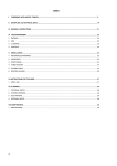
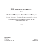
Freescale Semiconductor
Application Note
AN2551
Rev. 1, 08/2005
MPC5200 Startup Code
by: Mark Jonas
1
Introduction
This application note describes the procedures necessary
to initialize a MPC5200 processor and to begin executing
programs compiled using the Embedded Application
Interface (EABI) for PowerPC processors. All source
code is target to run on the IceCube+ MPC5200
Evaluation Platform when it is compiled using GNU gcc
2.95.3. However, the source code is written so that it can
be ported to any other MPC5200 board with little effort.
The boot code presented in this document only does a
minimum what is needed to execute a program written
according to the EABI specification and is designed to
run from system reset. Other exceptions are not handled
by the code. Instead, empty handlers are supplied which
will prevent the further execution of the program once
they are called. If the users whish to add their own
exception handling functions this can be done easily in
exactly the same way the system reset exception handler
is called.
The boot code also demonstrates how to gain basic
access to the memory management unit (MMU) of the
MPC5200. Access protection via block address
© Freescale Semiconductor, Inc., 2005. All rights reserved.
Table of Contents
1 Introduction . . . . . . . . . . . . . . . . . . . . . . . . . . . . . . . .1
2 MPC5200 Initialization . . . . . . . . . . . . . . . . . . . . . . . .2
2.1
2.2
2.3
2.4
2.5
General Initialization . . . . . . . . . . . . . . . . . . . . . .2
SDRAM Controller . . . . . . . . . . . . . . . . . . . . . . . .2
Memory Management Unit . . . . . . . . . . . . . . . . .3
Caches. . . . . . . . . . . . . . . . . . . . . . . . . . . . . . . . .3
EABI Register Initialization . . . . . . . . . . . . . . . . .4
3 PowerPC EABI Compliance . . . . . . . . . . . . . . . . . . . .4
4 Sample Boot Code . . . . . . . . . . . . . . . . . . . . . . . . . . .5
4.1
4.2
4.3
4.4
4.5
4.6
Configurable Options . . . . . . . . . . . . . . . . . . . . . .6
General Initialization . . . . . . . . . . . . . . . . . . . . . .7
EABI Register Initialization . . . . . . . . . . . . . . . . .9
Moving from ROM to RAM. . . . . . . . . . . . . . . . . .9
GCC Compilation and Linking . . . . . . . . . . . . . . .9
Example User Program . . . . . . . . . . . . . . . . . . .10
5 Source Code . . . . . . . . . . . . . . . . . . . . . . . . . . . . . .10
6 Literature . . . . . . . . . . . . . . . . . . . . . . . . . . . . . . . . .11
MPC5200 Initialization
translation (BAT) as well as the usage of data and instruction cache are demonstrated. More advanced
features of the MMU which provide support for paging and segmentation are not utilized.
Before starting the EABI user program the boot code copies the code and data of the program from ROM
to RAM and calls the main () function of the user program. An example user program is supplied which
demonstrates C level access of MPC5200 peripherals.
This application note is based on the application note A Minimal PowerPC Boot Sequence for Executing
Compiled C Programs (AN1809/D).
2
MPC5200 Initialization
2.1
General Initialization
Like most other PowerPC processor MPC5200 is at power up in a minimal state with most features, such
as caching and address translation, disabled. External interrupts, the machine check exception, floating
point exceptions and the time base registers (DEC, TBU and TBL) are also disabled. The exception prefix
is configured by the Reset Configuration Word. If this application note speaks about “boot low” the
exception prefix is set to 0x0000_0000. 0xFFF0_0000 means “boot high”. This means upon system reset
(exception vector 0x0100) the processor executes code beginning at 0x0000_0100 (boot low) or
0xFFF0_0100 (boot high).
The code located at the system reset vector must handle system initialization. Exceptions for PowerPC
processors are located at increments of 0x0100 from the vector table start address. Because of this the
initialization code must fit in such a slot of 256 bytes (64 PowerPC instructions). As the boot code
presented here does not fit in this slot the system reset code branches to an address located beyond the end
of the exception table’s allocated space. 0x3000 bytes (12 kilobytes) are reserved for the exception vector
table.
The only chip select active at power up is CSBoot. Depending on the configuration of the exception prefix
it is set to start from 0x0000_0000 or 0xFFF0_0000. In both cases it covers 512 kilobytes. To unify the the
two cases the boot code sets up CS0 to map the address range from 0xFF80_0000 to 0xFFFF_FFFF, moves
execution to this range and disables CSBoot. Anyhow, CSBoot and CS0 share the same physical chip
select pin.
2.2
SDRAM Controller
When initializing the SDRAM Controller the following sequence is suggested:
• If SDRAM CS1 is used, configure GPIO Port Configuration Register (GPS peripheral)
accordingly
• Set up SDRAM CS0 and CS1 (MM peripheral)
• Configure SDRAM Controller (SDRAM peripheral)
• Write tap delay to Power On Reset Configuration Register (CDM peripheral)
MPC5200 Startup Code, Rev. 1
2
Freescale Semiconductor
MPC5200 Initialization
Details can be found in the source code accompanying this application note and the MPC5200 User
Manual [1].
2.3
Memory Management Unit
The boot code sets up the MMU if memory management is required. Using the MMU to translate memory
addresses allows the programmer to specify protection and access control for individual regions of
memory. For a minimal system with eight or fewer memory regions, it is sufficient to use block address
translation (BAT) to perform rudimentary mapping. For more complex systems, the segment registers and
page tables need to be initialized. This application note only addresses the minimal configuration using the
BAT registers. For documentation about using BAT registers and the MMU, refer to Programming
Environments Manual for 32-Bit Implementations of the PowerPC Architecture (MPCFPE32B/AD) [2]
and G2 Core Reference Manual (G2CORERM/D) [3].
When using the MMU to provide address translation via the BAT registers, each region of memory in the
system should have an associated BAT mapping. These mappings allow the programmer to specify options
such as whether the specified address range is valid for supervisor or user mode, the memory/cache access
mode and the protection bits for the block. There are sixteen BAT array entries. Eight of these map data
regions (DBATs), while the remaining eight entries specify instruction regions (IBATs). See [2] for details
on using the BAT registers.
In a complete operating system, MMU setup continues with invalidating TLB entries, initializing the
segment registers and setting up the page table. Even if only BAT mappings are used for translation it is
possible that a user program may generate accesses to addresses that are invalid or not mapped by the BAT
registers. In this case the processor attempts to look at the page table to resolve the reference. If the page
table pointer and entries have not been initialized it is possible that they may contain random data and
cause unintended memory accesses.
When the MMU setup completes, the MMU may be enabled by setting MSR bits 26 and 27, Instruction
Address Translation (IR) and Data Address Translation (DR). At this point address translation is active.
2.4
Caches
At power-up instruction and data caches are disabled. These should be turned on to boost program
performance. To turn on the instruction cache set bit 16, Instruction Cache Enable (ICE), in the Hardware
Implementation Register 0 (HID0). Data cache is enabled by setting bit 17, Data Cache Enable (DCE), in
the same register. An isync instruction should be issued before setting the ICE bit to ensure that the cache
is not enabled or disabled during an instruction fetch. Similarly, a sync instruction should be executed
before setting the DCE bit.
Memory regions that represent processor internal or external peripherals should not be cached. Else, it is
possible that values written to these regions are not written immediately when using copy back caching or
that changes in the hardware are not reflected in the values read from the cache. Therefore, the caches
should be disabled whenever the MMU is disabled.
Note that simply enabling the caches is not sufficient to ensure that the caches will be used if the MMU is
enabled. Memory regions where the user data resides should be mapped as non-cache-inhibited in order
MPC5200 Startup Code, Rev. 1
Freescale Semiconductor
3
PowerPC EABI Compliance
to make use of the cache. See Section 2.3, Memory Management Unit for more information on mapping
memory regions.
2.5
EABI Register Initialization
In order for user applications to run correctly, registers specified by the Embedded Application Binary
Interface (EABI) must be set up. This is handled by the __eabi() startup code and the code that executes
prior to entry into main(). The sample boot code provides a simple __eabi() function that initializes
registers GPR2 and GPR13. GPR1 is initialized prior to the call to main() by the initialization sequence.
Section 3, PowerPC EABI Compliance describes these registers and the other EABI register conventions
in more detail.
3
PowerPC EABI Compliance
The PowerPC EABI specifies the system interface for compiled programs. The EABI is based on the
System V Application Binary Interface [4] and the PowerPC Processor Supplement [5]. For general ABI
documentation, refer to these documents, as well as the PowerPC Embedded Application Binary Interface
[6]. This application note only includes aspects of the EABI that apply directly to preparing to jump into
a compiled C program.
For running compiled programs, the EABI-specified register conventions must be followed. The EABI
defines how the processor’s registers are to be used by a conforming application. Table 1 lists the register
conventions for the PowerPC EABI.
Table 1. PowerPC EABI Registers
Register
Type
Contents
GPR0
Volatile
GPR1
Dedicated
Stack Frame Pointer (SP)
GPR2
Dedicated
Read-only small data anchor (_SDA2_BASE)
GPR3 - GPR4
Volatile
Parameter passing / return values
GPR5 - GPR10
Volatile
Parameter passing
GPR11 - GPR12
Volatile
GPR13
Dedicated
GPR14 - GPR31
Nonvolatile
FPR0
Volatile
Language specific
FPR1
Volatile
Parameter passing / return values
FPR2- FPR8
Volatile
Parameter passing
FPR9 - FPR13
Volatile
Language specific
Read-write small data anchor (_SDA_BASE)
MPC5200 Startup Code, Rev. 1
4
Freescale Semiconductor
Sample Boot Code
Table 1. PowerPC EABI Registers (continued)
Register
Type
FPR14 - FPR31
Nonvolatile
Fields CR2 - CR4
Nonvolatile
Other CR fields
Volatile
Other registers
Volatile
Contents
The symbols _SDA_BASE and _SDA2_BASE are defined during linking. They specify the locations of
the small data areas (read-write and read-only). A program must load these values into GPR13 and GPR2,
respectively, before accessing program data.
The small data areas contain part of the data of the executable. They hold a number of variables that can
be accessed within a 16-bit signed offset of _SDA_BASE or _SDA2_BASE. References to these variables
are performed through references to GPR13 and GPR2 by the user program. Typically, the small data areas
contain program variables that are less than or equal to 8 bytes in size, although this differs by compiler
and is usually adjustable, too.
Before executing user code, the startup code must also set up the stack pointer in GPR1. This pointer must
be 8-byte aligned for the EABI (as opposed to 16-byte aligned for the PowerPC ABI) and should point to
the lowest allocated valid stack frame. The stack grows toward lower addresses, so its location should be
selected so that it does not grow into text, data or bss areas.
Much of the required EABI register setup is accomplished through a call to __eabi(). The user does not
call this function directly. Instead, the compiler inserts the call to __eabi() at the beginning of main() in the
user program. Most compile environments provide an __eabi() function that is automatically linked with
user programs. Unfortunately, this standard __eabi() is often designed to work with a particular operating
system or environment. Because the processor is using the source in this application note, a minimal
__eabi() function is supplied to handle these specific requirements.
The remainder of the registers are listed for completeness and are not modified by the minimal boot code.
They may be modified by the user program.
4
Sample Boot Code
The sample boot code that accompanies this application note performs a minimal processor setup, chip
select configuration and SDRAM controller initialization and executes a user program. Other peripherals
are not initialized and external and critical interrupts are left disabled. It is designed for use with the
IceCube+ MPC5200 Evaluation Platform and was tested using GNU gcc 2.95.3 and GNU binutils 2.11.92.
This code sequence is designed to take the place of the traditional crt0 module, as well as to provide
hardware initialization normally performed by operating the system.
The basic operation of the boot sequence is as follows:
1. Invalidate BAT entries.
2. Set up BAT registers to provide address translation and protection.
3. Invalidate TLB entries.
MPC5200 Startup Code, Rev. 1
Freescale Semiconductor
5
Sample Boot Code
4. Turn on address translation.
5. Set up SDRAM controller.
6. Relocate the text, data and bss sections from ROM to RAM.
7. Enable caches.
8. Place the user code main() entry address in SSR0
9. Put the MSR value for the user program into SRR1.
10. Save the return address in the link register.
11. Set up a stack pointer in GPR1 for the user program.
12. Execute rfi. This executes the user program by jumping to the address stored in SRR0. Before
running the user code, a compiler-inserted call to __eabi() sets up EABI registers GPR2 and
GPR13.
13. Perform an endless loop in case the user program exits.
This procedure may be modified or configured to match the desired configuration.
4.1
Configurable Options
The design of the boot code allows it to be easily configurable. The many options defined in the header
file init.h allow the user to choose how the code should execute. These option are summarized in Table 2.
Table 2. User-Configurable Program Options
Option
MMU_ON
Definition
Specifies whether or not to use the MMU.
1 = MMU on
0 = MMU off
ICACHE_ON
Specifies whether to turn on the instruction cache.
1 = icache on
0 = icache off
DCACHE_ON
Specifies whether to turn on the data cache.
1 = dcache on
0 = dcache off
DDR
EMODE
MODE
Specifies the kind of SDRAM used.
1= DDR
0= SDR
Value to write to the Extended Mode Register of the DDR SDRAM chip(s) during initialization of
the SDRAM controller.
Value to write to the Mode Register of the SDRAM chip(s) during initialization of the SDRAM
controller.
CONTROL
Value to write to the Control Register of the SDRAM controller.
CONFIG1
Value to write to the Config1 Register of the SDRAM controller.
CONFIG2
Value to write to the Config2 Register of the SDRAM controller.
TAP_DEL
Tap Delay to be used when accessing SDRAM.
RAM_START
RAM_SIZE
Start address of the SDRAM. Should be 0x0000_0000 for this boot code.
Size of SDRAM in MPC5200 SDRAM Chip Select notation. See [1], Memory Map chapter.
MPC5200 Startup Code, Rev. 1
6
Freescale Semiconductor
Sample Boot Code
Table 2. User-Configurable Program Options (continued)
Option
Definition
FLASH_START
Flash memory range start address. Should be 0xFF80_0000 for the IceCube+ board.
FLASH_STOP
Flash memory range stop address. Should be 0xFFFF_FFFF for this boot code.
STACK_LOC
Initialization value of the stack pointer. Make sure that the stack does not grown into text, data or
bss sections.
PROM_BASE
The start address of the address range corresponding to the physical address of the Flash.
PRAM_BASE
The start address of the address range corresponding to the physical address of the SDRAM.
PMBAR
The start address of the address range corresponding to the physical address of the internal
peripheral address space. Should be 0x8000_0000 as MBAR is not move by the boot code.
VROM_BASE
The start address of the address range corresponding to the virtual address of the Flash.
VRAM_BASE
The start address of the address range corresponding to the virtual address of the SDRAM.
VMBAR
The start address of the address range corresponding to the virtual address of the internal
peripheral address space.
IBATxL_VAL
Specifies the 32-bit value for the lower BAT register for instruction BAT array entry x (x=0 to 7).
IBATxU_VAL
Specifies the 32-bit value for the upper BAT register for instruction BAT array entry x (x=0 to 7).
DBATxL_VAL
Specifies the 32-bit value for the lower BAT register for data BAT array entry x (x=0 to 7).
DBATxU_VAL
Specifies the 32-bit value for the upper BAT register for data BAT array entry x (x=0 to 7).
The locations of the text, data and bss sections are defined in the linker definition script linkerscript.lds.
These addresses control the location of the various sections in the compiled program both when
programming the image to ROM or when the sections are relocated from ROM to RAM by the boot code.
To aid the user in flashing the boot code and the user program easily using the dBUG monitor program the
Load Memory Address (LMA) is set to 0x0002_0000 as this is the first address in SDRAM not used by
dBUG and is available to the user. The place from where the code is being execute is the Virtual Memory
Address (VMA). This is set to 0x0000_0000 for this boot code because SDRAM starts at this address after
it is set up.
4.2
General Initialization
Processor initialization in the sample boot code follows the steps outlined in Section 2, MPC5200
Initialization. One of the most important tasks of the boot code is to set the value of the MSR for the user
program. Specifically, the MSR is set up to enable floating-point and machine check exceptions. The
exceptions prefix is set to 0x0000_0000 as the text section including the exception vector table is copied
from ROM to RAM and the SDRAM starts at 0x0000_0000.
MPC5200 Startup Code, Rev. 1
Freescale Semiconductor
7
Sample Boot Code
Boot High
1
2
3
2b
3
CSBoot
CS0
SDRAM
Boot Low
1
2a
Figure 1. Chip Selects During Boot
The order in which the chip selects are enabled and disabled during boot is shown in Figure 1. When
booting high execution starts at 0xFFF0_0000. Then CS0 is set up and covers the same area CSBoot
covers. Then it is enabled and CSBoot is disabled in the same moment. Boot low is a little bit more
complicated. CS0 is set up just like when booting low but instead of disabling CSBoot when enabling CS0
it stays active. Before CSBoot can be disabled execution must be moved to the alias address in CS0. When
that has been accomplished CSBoot can be deactivated.
The caches are invalidated and disabled during the majority of the boot code. This prevents program data
from being preloaded into the caches, which would unfairly speed up a benchmark. Before branching into
the user program the boot code enables instruction and data caches if ICACHE_ON and DCACHE_ON
are set to 1 respectively. Finally, if MMU_ON is set to 1, the boot code initializes the BAT registers and
enables address translation.
MPC5200 Startup Code, Rev. 1
8
Freescale Semiconductor
Sample Boot Code
4.3
EABI Register Initialization
In order for a C program compiled with an EABI-compliant compiler to execute properly, registers GPR1,
GPR2 and GPR13 must be initialized as described in Section 3, PowerPC EABI Compliance GPR1 should
be loaded with STACK_LOC, the location of the stack reserved for the user program defined in init.h.
Care should be taken to ensure that the stack size is sufficient and that it does not grow into text, data or
bss sections of the program during execution.
The EABI registers GPR2 and GPR13 are initialized by the __eabi() function. The call to __eabi() is
automatically inserted at the beginning of main() by the compiler. It should not be called directly by the
user program unless the user does not have a main() function. Programs that lack main() should call
__eabi() before executing any user code.
4.4
Moving from ROM to RAM
The code relocation depends on the variables that are allocated in the file linkerscript.lds. The text, data
and bss sections are copied from ROM to RAM using these variables.
The first section that is relocated is the text section. The relocation code looks at the linkerscript.lds
variable __text_start and the location of the section in ROM to determine if the text section must be
relocated. If the addresses are not the same, the section is relocated.
The length of the text section is stored in the variable __text_size. The size of the section must be a multiple
of 64 bytes as the copy loop is speed optimized for this. That the size is a multiple of 64 bytes is ensured
by linkerscript.lds. The text section is relocated from ROM to RAM to speed up the execution of
programs as access to ROM are usually slower than to RAM.
Next, the data and bss section are relocated. Their location is also marked by a start address (__data_start,
_bss_start) as well as a size in bytes (__data_size, __bss_size), which must be a multiple of 64 bytes again.
The data and sections are relocated from ROM to RAM not only to speed up the access to data but also to
allow the user code to modify the data.
The bss section is not actually copied since it only holds uninitialized data. Instead, the region starting at
__bss_start is initialized to all zeroes for __bss_size bytes. This code may be commented out for programs
which do not depend on zero-filled bss.
Execution from the relocated text section in RAM starts when the boot code jumps to main() using the rfi
instruction.
4.5
GCC Compilation and Linking
The compilation and linking procedure for a standalone bootable program is fairly complex. The compiled
program should not include standard libraries or startup code, and needs to be in a format that can be used
to program the Flash memory of the board. Most importantly, the code needs to be located at a specific
absolute start address so that it begins execution on system reset. In addition, the executable needs to be
built so that references to symbols and variables refer to the location of variables after the relocation to
RAM has occurred. Most of this work is accomplished through the use of a linker script.
MPC5200 Startup Code, Rev. 1
Freescale Semiconductor
9
Source Code
The compilation procedure described here uses GNU gcc 2.95.3 and GNU binutils 2.11.92 which are free
and publicly available from many different source on the Internet. The GNU make utility is also used.
The file Makefile is the makefile for the boot code and an example user program. It is written in a quite
flexible way so that source files can be added or removed easily by editing the makefile variable SRCS.
Dependencies between the source files and their includes are maintained using an automatically generated
dependency file depend.
The tools needed for compilation, linking and object file maintenance must be passed through the variables
CC, LD, OC, MKDEP and RM. CC defines the C compiler (default ’powerpc-eabi-gcc’), LD defines the
linker (default ’powerpc-eabi-ld’), OC a program to convert one object file format into another (default
’powerpc-eabi-objcopy’), MKDEP the dependency file generator (default ’powerpc-eabi-gcc -MM’) and
RM a program to delete files (default ’rm -rf’).
When using the default target the makefile will generate four main output files. mpc5200startup.elf is an
image of the compiled program in ELF format. mpc5200startup.mot and mpc5200startup.bin represent
the same image but in S-Record and Binary format respectively. Additionally, mpc5200startup.map is a
map file showing the symbols and their location in the image.
The linker script linkerscript.lds controls how the GNU linker will put together the object files the project
consists of in one executable image. The linker script groups together the various segments (.text, .rodata,
.data, .sdata, .sdata2, .bss, .sbss, ...) generated by the compiler into sections which are then arranged in the
LMA and VMA memory map, see Section 4.2, General Initialization.
4.6
Example User Program
All source files (*.S, *.c, *.h) except vectors.S, init.S, init.h and reg_defs.h belong to the example user
program. The user program implements a Sieve of Erastostenes benchmark timing how long it takes to
find all primes between 0 and 100000. To print its results the program initializes PSC1 to UART mode at
115200 Baud, 8N1. To measure the time elapsed while the program calculated the primes the core’s time
base registers TBU and TBL are used.
The program can be used to experiment with the various cache and MMU settings as well as a basis for
own benchmarks. Of course, it can be used as an example for programming any other kind of application
as well.
5
Source Code
The source code accompanying this application note is not printed here because it would span to many
pages. It can be downloaded from the same place on the Freescale Semiconductor, Inc. (formerly
Motorola) web page where this application note was found.
MPC5200 Startup Code, Rev. 1
10
Freescale Semiconductor
Literature
6
Literature
[1] MPC5200 User Manual ( Freescale [formerly Motorola])
[2] Programming Environments Manual for 32-Bit Implementations of the PowerPC Architecture (
Freescale [formerly Motorola], MPCFPE32B/AD)
[3] G2 Core Reference Manual (Freescale [formerly Motorola], G2CORERM/D)
[4] System V Application Binary Interface
[5] PowerPC Processor Supplement
[6] PowerPC Embedded Application Binary Interface
[7] Developing PowerPC Embedded Application Binary Interface (EABI) Compliant Programs (IBM)
[8] A Minimal PowerPC Boot Sequence for Executing Compiled C Programs (AN1809/D)
MPC5200 Startup Code, Rev. 1
Freescale Semiconductor
11
How to Reach Us:
Home Page:
www.freescale.com
E-mail:
[email protected]
USA/Europe or Locations Not Listed:
Freescale Semiconductor
Technical Information Center, CH370
1300 N. Alma School Road
Chandler, Arizona 85224
+1-800-521-6274 or +1-480-768-2130
[email protected]
Europe, Middle East, and Africa:
Freescale Halbleiter Deutschland GmbH
Technical Information Center
Schatzbogen 7
81829 Muenchen, Germany
+44 1296 380 456 (English)
+46 8 52200080 (English)
+49 89 92103 559 (German)
+33 1 69 35 48 48 (French)
[email protected]
Japan:
Freescale Semiconductor Japan Ltd.
Headquarters
ARCO Tower 15F
1-8-1, Shimo-Meguro, Meguro-ku,
Tokyo 153-0064
Japan
0120 191014 or +81 3 5437 9125
[email protected]
Asia/Pacific:
Freescale Semiconductor Hong Kong Ltd.
Technical Information Center
2 Dai King Street
Tai Po Industrial Estate
Tai Po, N.T., Hong Kong
+800 2666 8080
[email protected]
For Literature Requests Only:
Freescale Semiconductor Literature Distribution Center
P.O. Box 5405
Denver, Colorado 80217
1-800-441-2447 or 303-675-2140
Fax: 303-675-2150
[email protected]
AN2551
Rev. 1, 08/2005
Information in this document is provided solely to enable system and software
implementers to use Freescale Semiconductor products. There are no express or
implied copyright licenses granted hereunder to design or fabricate any integrated
circuits or integrated circuits based on the information in this document.
Freescale Semiconductor reserves the right to make changes without further notice to
any products herein. Freescale Semiconductor makes no warranty, representation or
guarantee regarding the suitability of its products for any particular purpose, nor does
Freescale Semiconductor assume any liability arising out of the application or use of any
product or circuit, and specifically disclaims any and all liability, including without
limitation consequential or incidental damages. “Typical” parameters that may be
provided in Freescale Semiconductor data sheets and/or specifications can and do vary
in different applications and actual performance may vary over time. All operating
parameters, including “Typicals”, must be validated for each customer application by
customer’s technical experts. Freescale Semiconductor does not convey any license
under its patent rights nor the rights of others. Freescale Semiconductor products are
not designed, intended, or authorized for use as components in systems intended for
surgical implant into the body, or other applications intended to support or sustain life,
or for any other application in which the failure of the Freescale Semiconductor product
could create a situation where personal injury or death may occur. Should Buyer
purchase or use Freescale Semiconductor products for any such unintended or
unauthorized application, Buyer shall indemnify and hold Freescale Semiconductor and
its officers, employees, subsidiaries, affiliates, and distributors harmless against all
claims, costs, damages, and expenses, and reasonable attorney fees arising out of,
directly or indirectly, any claim of personal injury or death associated with such
unintended or unauthorized use, even if such claim alleges that Freescale
Semiconductor was negligent regarding the design or manufacture of the part.
Freescale™ and the Freescale logo are trademarks of Freescale Semiconductor, Inc.
All other product or service names are the property of their respective owners.
© Freescale Semiconductor, Inc. 2004, 2005. All rights reserved.