1
CUSTOMER NOTIFICATION
ZUD-CD-06-0006 (1/44)
March 6, 2006
Koji Nishibayashi, Group Manager
Development Tool Group
Multipurpose Microcomputer Systems Division
4th Systems Operations Unit
NEC Electronics Corporation
CP(K), O
Preliminary User’s Manual
QB-Programmer
Programming GUI
Operation
QB-Programmer Programming GUI Preliminary User’s Manual
[MEMO]
ZUD-CD-06-0006
2/44
QB-Programmer Programming GUI Preliminary User’s Manual
ZUD-CD-06-0006
3/44
MINICUBE is a registered trademark of NEC Electronics Corporation in Japan and Germany.
Windows is either a registered trademark or a trademark of Microsoft Corporation in the United States
and/or other countries.
PC/AT is a trademark of International Business Machines Corporation.
• The information in this document is current as of March 2006. The information is subject to change
without notice. For actual design-in, refer to the latest publications of NEC Electronics data sheets or
data books, etc., for the most up-to-date specifications of NEC Electronics products. Not all
products and/or types are available in every country. Please check with an NEC Electronics sales
representative for availability and additional information.
• No part of this document may be copied or reproduced in any form or by any means without the prior
written consent of NEC Electronics. NEC Electronics assumes no responsibility for any errors that may
appear in this document.
• NEC Electronics does not assume any liability for infringement of patents, copyrights or other intellectual
property rights of third parties by or arising from the use of NEC Electronics products listed in this document
or any other liability arising from the use of such products. No license, express, implied or otherwise, is
granted under any patents, copyrights or other intellectual property rights of NEC Electronics or others.
• Descriptions of circuits, software and other related information in this document are provided for illustrative
purposes in semiconductor product operation and application examples. The incorporation of these
circuits, software and information in the design of a customer's equipment shall be done under the full
responsibility of the customer. NEC Electronics assumes no responsibility for any losses incurred by
customers or third parties arising from the use of these circuits, software and information.
• While NEC Electronics endeavors to enhance the quality, reliability and safety of NEC Electronics products,
customers agree and acknowledge that the possibility of defects thereof cannot be eliminated entirely. To
minimize risks of damage to property or injury (including death) to persons arising from defects in NEC
Electronics products, customers must incorporate sufficient safety measures in their design, such as
redundancy, fire-containment and anti-failure features.
• NEC Electronics products are classified into the following three quality grades: "Standard", "Special" and
"Specific".
The "Specific" quality grade applies only to NEC Electronics products developed based on a customerdesignated "quality assurance program" for a specific application. The recommended applications of an NEC
Electronics product depend on its quality grade, as indicated below. Customers must check the quality grade of
each NEC Electronics product before using it in a particular application.
"Standard": Computers, office equipment, communications equipment, test and measurement equipment, audio
and visual equipment, home electronic appliances, machine tools, personal electronic equipment
and industrial robots.
"Special": Transportation equipment (automobiles, trains, ships, etc.), traffic control systems, anti-disaster
systems, anti-crime systems, safety equipment and medical equipment (not specifically designed
for life support).
"Specific": Aircraft, aerospace equipment, submersible repeaters, nuclear reactor control systems, life
support systems and medical equipment for life support, etc.
The quality grade of NEC Electronics products is "Standard" unless otherwise expressly specified in NEC
Electronics data sheets or data books, etc. If customers wish to use NEC Electronics products in applications
not intended by NEC Electronics, they must contact an NEC Electronics sales representative in advance to
determine NEC Electronics' willingness to support a given application.
(Note)
(1) "NEC Electronics" as used in this statement means NEC Electronics Corporation and also includes its
majority-owned subsidiaries.
(2) "NEC Electronics products" means any product developed or manufactured by or for NEC Electronics (as
defined above).
M8E 02. 11-1
QB-Programmer Programming GUI Preliminary User’s Manual
ZUD-CD-06-0006
4/44
INTRODUCTION
Target Readers
This manual is intended for users who use the QB-Programmer when designing and
developing a system using an NEC Electronics on-chip flash memory microcontroller.
Purpose
This manual is intended to give users an understanding of the basic specifications
and correct use of the QB-Programmer.
Organization
This manual includes the following sections.
• Overview
• Software installation
• Software usage
• Troubleshooting
How to Read This Manual
It is assumed that the readers of this manual have general knowledge of electricity,
logic circuits, and microcontrollers.
In the explanations of the operation of the
applications, it is also assumed that the readers have sufficient knowledge of
Windows. For the usage and terminology of Windows 98, Windows Me, Windows
2000, and Windows XP, refer to each Windows manual.
To understand the overall operation of the QB-Programmer
→ Read this manual according to the CONTENTS.
To know the basic specifications, usages, and usage examples of hardware
→ See the QB-MINI2 On-Chip Debug Emulator with Programming Function
User’s Manual (ZUD-CD-06-0018).
QB-Programmer Programming GUI Preliminary User’s Manual
Conventions
ZUD-CD-06-0006
Note:
Footnote for item marked with Note in the text
Caution:
Information requiring particular attention
Remark:
Supplementary information
Numeric representation:
Binary ... xxxx or xxxxB
5/44
Decimal ... xxxx
Hexadecimal ... xxxxH
Prefix indicating power of 2 (address space, memory capacity):
10
K (kilo): 2
= 1,024
20
M (mega): 2
Terminology
= 1,0242
The meanings of the terms used in this manual are as follows.
Term
Meaning
MINICUBE2
General name of QB-MINI2, on-chip debug emulator with programming
function
QBP
Abbreviation of programming GUI QB-Programmer
Target device
NEC Electronics on-chip flash memory microcontroller
Target system
User-designed board on which NEC Electronics on-chip flash memory
microcontroller is mounted
Target board
Target board for MINICUBE2, on which NEC Electronics on-chip flash
memory microcontroller is mounted
FA adapter
Conversion adapter to write programs to NEC Electronics on-chip flash
memory microcontrollerNote
Note The FA adapter (FA-xxxx) is a product of Naito Densei Machida Mfg. Co., Ltd.
If you have any questions about the FA adapter board, contact:
Naito Densei Machida Mfg. Co., Ltd. Tel: +81-45-475-4191
Related Documents
Please use the following documents in combination with this manual.
The related documents listed below may include preliminary versions. However,
preliminary versions are not marked as such.
{ Documents Related to Development Tools (User’s Manuals)
Document Name
Document Number
QB-Programmer Programming GUI OPeration
This document
QB-MINI2 On-Chip Debug Emulator with Programming Function
ZUD-CD-06-0018
MINICUBE2 Self-Testing Tool
ZUD-CD-06-0044
Caution The related documents listed above are subject to change without
notice. Be sure to use the latest version of each document for
designing, etc.
QB-Programmer Programming GUI Preliminary User’s Manual
ZUD-CD-06-0006
6/44
CONTENTS
CHAPTER 1
OVERVIEW ......................................................................................................................................... 7
1.1 Features .......................................................................................................................................................... 7
1.2 Writing Quality................................................................................................................................................. 7
1.3 Supported Devices .......................................................................................................................................... 7
1.4 System Configuration ...................................................................................................................................... 8
1.5 Operating Environment ................................................................................................................................... 9
CHAPTER 2
SOFTWARE INSTALLATION............................................................................................................ 10
2.1 Obtaining Software........................................................................................................................................ 10
2.2 Installation ..................................................................................................................................................... 10
2.3 Uninstallation................................................................................................................................................. 11
2.4 Updating Firmware ........................................................................................................................................ 12
2.5 MINICUBE2 Self-Testing Tool ....................................................................................................................... 12
CHAPTER 3
SOFTWARE USAGE......................................................................................................................... 13
3.1 Main Window................................................................................................................................................. 13
3.2 Menu Bar....................................................................................................................................................... 14
3.3 Toolbar .......................................................................................................................................................... 32
3.4
Action Log Window........................................................................................................................................ 32
3.5 Programmer Parameter Window................................................................................................................... 33
3.6 Progress Bar ................................................................................................................................................. 34
3.7 Status Bar...................................................................................................................................................... 34
CHAPTER 4
TROUBLESHOOTING ...................................................................................................................... 35
4.1 Problems During Startup ............................................................................................................................... 35
4.2 Problems During Operation........................................................................................................................... 36
APPENDIX A MESSAGES ..................................................................................................................................... 39
A.1 Message Format........................................................................................................................................... 39
A.2 Messages ..................................................................................................................................................... 40
APPENDIX B
REVISION HISTORY ....................................................................................................................... 44
QB-Programmer Programming GUI Preliminary User’s Manual
ZUD-CD-06-0006
7/44
CHAPTER 1 OVERVIEW
The programming GUI “QB-Programmer” (QBP) is a software tool that is used to erase, write, and verify programs
on the target system or FA adapter, on which an NEC Electronics single-power-supply on-chip flash memory
microcontroller is mounted, by using the on-chip debug emulator with programming function QB-MINI2
(MINICUBE2), via a 16-pin target cable (target cable). The QBP can also be used to perform self-testing and
firmware updates using the MINICUBE2 self-testing tool.
1.1
Features
The programming function has the following features when the QBP is used together with MINICUBE2.
• Supports single-power-supply on-chip flash memory microcontrollers
• Compact and lightweight
• Supports USB interface as a host interface
• Supports UART and CSI-H/S as a target device interface
• Reads device-specific parameters required for programming from the parameter file (*.PRM)
• Can supply 3 or 5 V power to the target device (max. 100 mA)
• Can supply 4, 8, or 16 MHz clock to the target device
• Can perform self-testing and firmware updates using the MINICUBE2 self-testing tool
1.2
Writing Quality
Thoroughly confirm, verify and evaluate the following points before using the QBP, in order to improve the writing
quality.
• Design circuits as described in the user’s manuals for the device and MINICUBE2.
• Use the device, QBP and MINICUBE2 as described in the user’s manual for each product.
• The power supplied to the target system is stable.
1.3
Supported Devices
For devices supported by the QBP, see the following document or website.
• Document: QB-MINI2 Operating Precautions
• URL: http://www.necel.com/micro/english/product/sc/allflash/minicube2.html
QB-Programmer Programming GUI Preliminary User’s Manual
1.4
ZUD-CD-06-0006
8/44
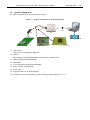
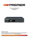
System Configuration
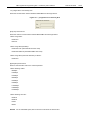
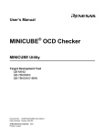
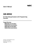
The system configuration for flash programming is as follows.
Figure 1-1.
System Configuration for Flash Programming
<5>
<6>
<3>
<1>
<4>
<2>
<7>
<8>
<1> Host machine
Those which are equipped with USB ports
<2> Software
QB-Programmer, USB driver, MINICUBE2 self-testing tool, parameter file, etc.
<3> USB cable (supplied with MINICUBE2)
<4> MINICUBE2
<5> 16-pin target cable (supplied with MINICUBE2)
<6> Target connector (sold separately)
<7> Target system
<8> Target board QB-xxxx-TB (sold separately)
<9> FA adapter FA-xxxx (sold separately; a product of Naito Densei Machida Mfg. Co., Ltd.)
<9>
QB-Programmer Programming GUI Preliminary User’s Manual
1.5
ZUD-CD-06-0006
9/44
Operating Environment
This section explains the following items with respect to the operating environment.
• Hardware environment
• Software environment
1.5.1
Hardware environment
(1) Host machines
• PC98-NX series, IBM PC/ATTM compatible
• USB 2.0 (compatible with 1.1)
(2) Supported hardware tool
• QB-MINI2
1.5.2
Software environment
(1) OS (any of the following)
• Windows 98
• Windows Me
• Windows 2000
• Windows XP
Caution
Installing the latest Service Pack for the OS used is recommended.
(2) Parameter file (separately available)
• Parameter file for the target device used
Reference Download the parameter file from the following NEC Electronics website (ODS).
URL: http://www.necel.com/micro/ods/eng/index.html
Remark
To search for the parameter file based on the device name, search the name under the [Each
Device Series] menu.
(3) Program files
• Motorola HEX format
• Intel HEX format
QB-Programmer Programming GUI Preliminary User’s Manual
ZUD-CD-06-0006
10/44
CHAPTER 2 SOFTWARE INSTALLATION
This chapter explains the following items for QBP installation.
• Obtaining software
• Installation
• Uninstallation
• Updating firmware
• MINICUBE2 self-testing tool
2.1
Obtaining Software
Download the QBP, USB driver, MINICUBE2 self-testing tool, and parameter file from the following NEC Electronics
website (ODS).
<QBP, USB driver, MINICUBE2 self-testing tool>
URL: http://www.necel.com/micro/ods/eng/tool/MINICUBE2_Software/list.html
<Parameter file>
URL: http://www.necel.com/micro/ods/eng/index.html
Remark
To search for the parameter file based on the device name, search for the name under the [Each Device
Series] menu.
Caution Use of the latest version of software is recommended.
If you wish to receive an upgrade
notification, complete the registration for the upgrade notification service, found on the ODS
home page.
2.2
Installation
This section explains how to install the QBP, USB driver, MINICUBE2 self-testing tool, and parameter file.
Table 2-1.
Installation
Item
Method
QBP
Run the downloaded executable file and complete installation following the
USB driver
directions on the installer screen.
MINICUBE2 self-testing
The MINICUBE2 self-testing tool is included in the MINICUBE utilities.
tool
Parameter file (*.PRM)
Run the downloaded self-extracting file. A *.PRM file is decompressed in a folder.
Copy the decompressed parameter file to an arbitrary folder.
QB-Programmer Programming GUI Preliminary User’s Manual
ZUD-CD-06-0006
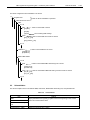
The folder configuration after installation is as follows.
C:\
\Program Files
Folder for which installation is specified
\NEC Electronics Tools
\QBP
\V1.00
\BIN
[qbp.exe]
Folder in which QBP is stored
[qbp.dll]
[qbp.ini]
File containing QBP settings
\DOC
Folder in which QBP documents are stored
[qbp_um_j.pdf]
[qbp_readme_j.pdf]
\V1.10
\MQB2ALL
Folder in which USB driver is stored
[mqb2all.sys]
[mqb2all.inf]
\MINICUBE Utilities
\V1.00
\BIN
Folder in which MINICUBE2 self-testing tool is stored
[mqb2utl.exe]
[ieocdutl.exe]
\DOC
Folder in which MINICUBE2 self-testing tool documents are stored
[utl_um_j.pdf]
[ocd_um_j.pdf]
\V1.10
2.3
Uninstallation
This section explains how to uninstall the QBP, USB driver, MINICUBE2 self-testing tool, and parameter file.
Table 2-2. Uninstallation
Item
Method
QBP
Open [Add/Remove Programs] (or [Add or Remove Programs]) on the Control
USB driver
Panel and uninstall these items.
MINICUBE2 self-testing
tool
Parameter file (*.PRM)
Delete the parameter file (*.PRM).
11/44
QB-Programmer Programming GUI Preliminary User’s Manual
2.4
ZUD-CD-06-0006
12/44
Updating Firmware
Firmware is a program that is embedded in the device for controlling MINICUBE2. Updating the firmware enables
the following.
• Addition of newly supported devices
• Removal of restrictions
For version confirmation of firmware, system configuration and update procedure, refer to the MINICUBE2
Self-Testing Tool User’s Manual.
Cautions 1. Use of the latest version of software is recommended. If you wish to receive an upgrade
notification, complete the registration for the upgrade notification service, found on the ODS
home page.
2. If update of firmware is improperly performed, MINICUBE2 may no longer operate.
Be sure to
refer to the MINICUBE2 Self-Testing Tool User’s Manual when updating firmware.
2.5
MINICUBE2 Self-Testing Tool
The MINICUBE2 self-testing tool can be used to find if the reason that the QBP does not operate normally derives
from a MINICUBE2 defect or from other hardware. For the usage, refer to the MINICUBE2 Self-Testing Tool
User’s Manual.
QB-Programmer Programming GUI Preliminary User’s Manual
ZUD-CD-06-0006
13/44
CHAPTER 3 SOFTWARE USAGE
This chapter explains functional details on windows and dialog boxes of the QBP.
Cautions 1. For the specifications, settings, connection, startup procedure and examples for basic usages
of MINICUBE2, refer to the QB-MINI2 On-Chip Debug Emulator with Programming Function
User’s Manual.
2. Be sure to remove the 78K0-OCD board.
3. Terminate the debugger, MINICUBE2 self-testing tool, and MINICUBE OCD Checker before
starting the QBP.
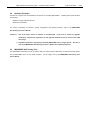
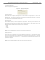
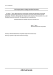
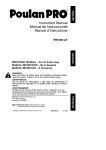
3.1
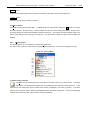
Main Window
In the Start menu, point to “All programs”, “NEC Electronics Tools”, “Latest Version”, and then choose
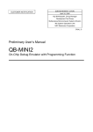
“QB-Programmer VX.XX” to start the QBP. When the QBP is started normally, the following screen appears.
Figure 3-1.
Main Window
<1> Menu bar
<4> Programmer parameter window
<2> Toolbar
<3> Action log window
<6> Status bar
<5> Progress bar
The main window consists of the following areas.
Name
Displayed Items
Refer to:
<1>
Menu bar
Menu items executable by the QBP
3.2
<2>
Toolbar
Frequently used commands, as button.
3.3
<3>
Action log window
A QBP action log
3.4
<4>
Programmer parameter window
Programming parameter settings.
3.5
<5>
Progress bar
Command progress shown as a percentage or with message
3.6
<6>
Status bar
Hints for commands and toolbar
3.7
QB-Programmer Programming GUI Preliminary User’s Manual
3.2
ZUD-CD-06-0006
14/44
Menu Bar
The menu bar displays the commands that are available for the QBP.
Some commands may be unavailable
depending on the parameter selected, or when the QBP is started for the first time.
Caution
3.2.1
During command execution do not execute another command or terminate the QBP.
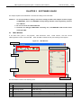
[File] menu
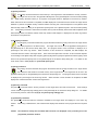
The following pull-down menu appears by clicking the [File] menu.
This menu includes commands related to file operation.
Figure 3-2. [File] Menu
(1)
(2)
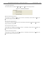
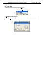
(1) [Load] command
The [Load] command selects a program file. When this command is executed, the program file select
dialog box appears. Browse the relevant folder and select the target program file in the folder. The
selected program file will be written to the flash memory in the target device, by executing the [Program] or
[Autoprocedure (EPV)] command.
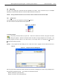
Remark
In the program file select dialog box, the folder from which a program file was selected last time is
displayed.
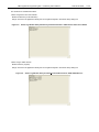
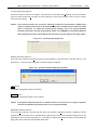
Figure 3-3. Program File Select Dialog Box
After the program file is selected, the QBP calculates the checksum and displays the result in the [Load file] area in
the programmer parameter window. The checksum is calculated as follows.
Method: Subtraction (16-bit arithmetic)
Range: From start to end of the program file
QB-Programmer Programming GUI Preliminary User’s Manual
Open
ZUD-CD-06-0006
15/44
button
Selects the specified program file as a program to be written to the flash memory in the target device.
Cancel
button
Closes the window without selecting a program.
(2) [Quit] command
The [Quit] command terminates the QBP.
The QBP can also be terminated by clicking the
×
button on the right
end of the title bar in the Main window. When the QBP is terminated, various settings are saved in the qbp.ini file,
and these settings are loaded when the QBP is started the next time. The settings include the settings made in the
Device Setup dialog box and the program file selected. The qbp.ini file is created in a folder where the QBP was
installed.
3.2.2
[Device] menu
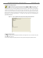
The following pull-down menu appears by clicking the [Device] menu.
This menu mainly consists of commands for programming the target device, such as erase, program and verify.
Figure 3-4. [Device] Menu
(1)
(2)
(3)
(4)
(5)
(6)
(7)
(8)
(9)
(10)
(1) [Blank Check] command
The [Blank Check] command performs blank check for the flash memory in the target device. The target
area can be set in the [Operation Mode] area on the [Standard] tab in the Device Setup dialog box. If the
flash memory has already been erased, “Blank Check PASS” is displayed in the action log window. If the flash
memory has not yet been erased, “Blank Check ERROR (E2008): Not Blank.” is displayed. If this error is displayed,
erase the entire area of the flash memory before starting programming.
QB-Programmer Programming GUI Preliminary User’s Manual
ZUD-CD-06-0006
16/44
(2) [Erase] command
The [Erase] command erases the flash memory in the target device and initializes the security functions.
The target area can be set in the [Operation Mode] area on the [Standard] tab in the Device Setup dialog
box. While erasing the flash memory is in progress, the progress status is displayed in the action log window.
When execution of this command is completed, the QBP displays the command execution result in the target device.
Whether to perform the [Blank Check] command before executing this command depends on the [Blank check
before Erase] check box setting in the [Command options] area on the [Advanced] tab in the Device Setup dialog
box.
If the [Erase] command is executed for the flash memory that has already been erased with the [Blank check
before Erase] check box selected, “Blank check Chip: PASS. Erase skipped.” is displayed in the action log window
and erasure is not performed.
(3) [Program] command
The [Program] command transmits the program file selected with the [Load] command to the target device
and writes programs to the flash memory. The target area can be set in the [Operation Mode] area on
the [Standard] tab in the Device Setup dialog box.
percentage in the action log window.
The progress status of this command is displayed as a
When execution of this command is completed, the QBP displays the
command execution result in the target device. Each command option after execution of this command depends
on the settings of the [Read verify after Program], [Security flag after Program] and [Checksum after Program] check
boxes in the [Command options] area on the [Advanced] tab in the Device Setup dialog box. For details on the
check boxes, refer to 3.2.2 (10) (b) <1> [Command options] area.
(4) [Verify] command
The [Verify] command transmits the program file selected with the [Load] command to the target device
and verifies the data written to the flash memory in the target device. The target area can be set in the
[Operation Mode] area on the [Standard] tab in the Device Setup dialog box. The progress status of this command
is displayed as a percentage in the action log window.
When execution of this command is completed, the QBP
displays the command execution result in the target device.
(5) [Security] command
The [Security] command sets the security functions for the target device and sets the boot area. These settings
can be made in the [Security flag settings] area on the [Advanced] tab in the Device Setup dialog box. For details
on the security function, refer to 3.2.2 (10) (b) <2> [Security flag settings] area.
(6) [Checksum] command
The [Checksum] command reads the checksum calculated in the target device and displays it in the action log
window. When using a 78K0S device, this command also displays the checksum of the program file and compares
both.
Caution The checksum read by this command differs from the one displayed in the [Load file] area in the
programmer parameter window.
QB-Programmer Programming GUI Preliminary User’s Manual
ZUD-CD-06-0006
17/44
The checksum is calculated as follows.
<When using device other than 78K0S>
Method: Subtraction (16-bit arithmetic)
Range: Area set in the [Operation Mode] area on the [Advanced] tab in the Device Setup dialog box
Figure 3-5.
Action Log Window After [Checksum] Command Execution <With Device Other Than 78K0S>
<When using a 78K0S device>
Method: Division (original)
Range: Area set in the [Operation Mode] area on the [Advanced] tab in the Device Setup dialog box
Figure 3-6.
Action Log Window After [Checksum] Command Execution <With 78K0S Device>
QB-Programmer Programming GUI Preliminary User’s Manual
ZUD-CD-06-0006
18/44
(7) [Autoprocedure (EPV)] command
The [Autoprocedure (EPV)] command continuously executes the [Erase] and [Program] commands. The
target area can be set in the [Operation Mode] area on the [Standard] tab in the Device Setup dialog box.
The progress status of this command is displayed in the action log window. When execution of this command is
completed, the QBP displays the command execution result in the target device. Each command option after
execution of this command depends on the settings of the [Blank check before Erase], [Read verify after Program],
[Security flag after Program], and [Checksum after Program] check boxes in the [Command options] area on the
[Advanced] tab in the Device Setup dialog box.
For details on the check boxes, refer to 3.2.2 (10) (b) <1>
[Command options] area.
Figure 3-7.
Action Log Window After [Autoprocedure (EPV)] Command Execution
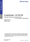
(8) [Signature Read] command
The [Signature Read] command reads signature information of the target device, such as the device name, flash
memory information, and so on.
The read result is displayed in the [Device] area in the action log window and programmer parameter window.
QB-Programmer Programming GUI Preliminary User’s Manual
ZUD-CD-06-0006
19/44
(9) [Get Security Settings] command
The [Get Security Settings] command reads the settings for the security functions for the target device and the boot
area and displays the result in the [Security flag settings] area on the [Advanced] tab in the Device Setup dialog box.
When execution of this command is enabled, execute this command before the [Security] command, check the
settings for the security functions or the boot area, and then add the security settings.
functions, refer to 3.2.2 (10) (b) <2> [Security flag settings] area.
Figure 3-8. [Get Security Settings] Command
For details on the security
QB-Programmer Programming GUI Preliminary User’s Manual
ZUD-CD-06-0006
20/44
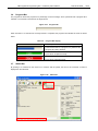
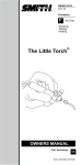
(10) [Setup] command
When the [Setup] command is executed, the Device Setup dialog box appears.
In this dialog box,
perform the settings in accordance with the user environment for flash memory programming, and set
command options and security settings.
Each time the QBP is started, the QBP loads the parameter file (.PRM)
that was used last and displays the settings. Settings for the items not dimmed can be changed in accordance with
the user environment. Switch the [Standard] and [Advanced] tabs for setting.
Figure 3-9. Device Setup Dialog Box
(a)
(b)
QB-Programmer Programming GUI Preliminary User’s Manual
ZUD-CD-06-0006
21/44
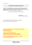
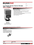
(a) [Standard] tab in Device Setup dialog box
On the [Standard] tab, set the programming environment of the flash memory in the target device.
This tab consists of the [Parameter File], [Target Device Connection], [Supply Oscillator], and [Operation Mode]
areas. The overall basic settings that are made in accordance with the user environment and target device are
available. The mode for communication with the target device, operating clocks, or the like that can be set vary
depending on the device used, so refer to the manual for each device.
Figure 3-10.
[Standard] Tab in Device Setup Dialog Box
<1>
<3>
<2>
<4>
OK
button
Saves the settings made on the [Standard] and [Advanced] tabs and closes the Device Setup dialog box.
Cancel
button
Closes the Device Setup dialog box without saving the settings made on the [Standard] and [Advanced] tabs.
QB-Programmer Programming GUI Preliminary User’s Manual
ZUD-CD-06-0006
22/44
<1> [Parameter File] area
Select the parameter file in this area. The selected parameter file name is displayed in this area.
Figure 3-11. [Parameter File] Area
PRM File Read
button
Clicking this button opens the parameter file select dialog box, so select the parameter file that has been copied in
an arbitrary folder.
Remark
In the parameter file select dialog box, the folder from which a parameter file was selected last time is
displayed.
Figure 3-12. Parameter File Select Dialog Box
Open
button
Selects the specified parameter file as a file to be written to the flash memory in the target device.
Cancel
button
Closes this dialog box without selecting a parameter file.
Remark
A parameter file contains timing data and parameters required for programming the flash memory in the
target device. Data in a parameter file affects the reliability of the programmed data, so do not change
the data. A parameter file is protected by the checksum; if the checksum result is invalid, the QBP will
not accept the parameter file.
QB-Programmer Programming GUI Preliminary User’s Manual
<2> [Target Device Connection] area
Select the communication channel between MINICUBE2 and the target device.
Figure 3-13. [Target Device Connection] Area
[Port] drop-down list box
Select the mode for communication between MINICUBE2 and the target device.
<When using V850>
• UART-ch0
• SIO-H/S
<When using 78K0 (All Flash)>
• UART-Ext-OSC (with external resonator used)
• UART-Ext-QB2CLK (with MINICUBE2 clock used)
<When using 78K0 (other than All Flash) or 78K0S>
• UART-ch0
[Speed] drop-down list box
Select a communication rate for the channel specified.
<When selecting UART>
• 9600bps
• 19200bps
• 31250bps
• 38400bps
• 57600bps
• 76800bps
• 115200bps
• 128000bps
• 153600bps
<When selecting SIO-H/S>
• 250KHz
• 500KHz
• 1MHz
• 2MHz
Remark For the selectable speed, refer to the user's manual for the device used.
ZUD-CD-06-0006
23/44
QB-Programmer Programming GUI Preliminary User’s Manual
ZUD-CD-06-0006
24/44
<3> [Supply Oscillator] area
Set the clock supplied to the target device.
Figure 3-14.
[Supply Oscillator] Area
[On Target] check box
Specify which clock is supplied to the target device: a clock mounted on the target system, or a clock on the
MINICUBE2 side. If this check box is selected, the clock mounted on the target system will be used. If this check
box is cleared, clock on the MINICUBE2 side will be used.
[Frequency] text box
Set the oscillation frequency of the clock supplied to the target device. When using the clock mounted on the
target system ([On Target] check box selected), input its oscillation frequency.
When using the clock on the
MINICUBE2 side ([On Target] check box cleared), input one of the following.
• 4 MHz
• 8 MHz
• 16 MHz
Remark For the selectable frequency, refer to the user's manual for the device used.
[Multiply rate] text box
Set the division ratio or multiplication ratio of the clock supplied to the target device. If the target device includes
the PLL circuit, input the division ratio or multiplication ratio in accordance with the environment used.
If the target
device does not include the PLL circuit, input “1.0”. In the initial screen, the default setting that is loaded from the
parameter file is displayed.
Remark For the selectable multiply rate, refer to the user's manual for the device used.
QB-Programmer Programming GUI Preliminary User’s Manual
ZUD-CD-06-0006
25/44
<4> [Operation Mode] area
Switch the operation mode: whether to execute commands, such as flash memory programming, for the entire flash
memory area, or in the block units. The settings made here are valid for the [Blank Check], [Erase], [Program],
[Verify], [Read], [Checksum], and [Autoprocedure (EPV)] commands.
Modes unavailable in the target device
cannot be selected.
Figure 3-15.
[Operation Mode] Area
If [Chip] is selected:
The entire flash memory area of the target device is subject to command processing, such as programming.
If [Block] is selected:
Specify the block range subject to the command processing, using the [Start] and [End] drop-down list boxes.
These lists show the block numbers where the flash memory in the target device is configured.
[Show Address] check box
Specify the display format in the [Start] and [End] drop-down list boxes. If this check box is selected, the block
address will be displayed. If this check box is cleared, the block number will be displayed.
QB-Programmer Programming GUI Preliminary User’s Manual
ZUD-CD-06-0006
26/44
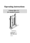
(b) [Advanced] tab in Device Setup dialog box
On the [Advanced] tab, set the command options to be added to a programming command and set the security
settings. This tab consists of the [Command options] and [Security flag settings] areas.
Figure 3-16. [Advanced] Tab in Device Setup Dialog Box
<1>
<2>
QB-Programmer Programming GUI Preliminary User’s Manual
ZUD-CD-06-0006
27/44
<1> [Command options] area
Set command options to be added to the [Erase], [Program], or [Autoprocedure (EPV)] command.
Figure 3-17.
[Command options] Area
[Blank check before Erase] check box
If this check box is selected, the [Blank Check] command is automatically executed before the [Erase] and
[Autoprocedure (EPV)] commands are executed.
[Read verify after Program] check box
If this check box is selected, the [Verify] command is automatically executed after the [Program] and [Autoprocedure
(EPV)] commands are executed.
[Security flag after Program] check box
If this check box is selected, the [Security] command is automatically executed after the [Program] and
[Autoprocedure (EPV)] commands are executed.
[Checksum after Program] check box
If this check box is selected, the [Checksum] command is automatically executed after the [Program] and
[Autoprocedure (EPV)] commands are executed.
QB-Programmer Programming GUI Preliminary User’s Manual
ZUD-CD-06-0006
28/44
<2> [Security flag settings] area
Specify the security functions to be enabled. When execution of the [Get Security Settings] command is enabled,
execute it before the [Security] command, check the settings for the security functions or the boot area, and then
add the security settings.
Caution
If the security functions are set and the [Security] command is executed with a 78K0S device
used, the security functions are set to the target device but not enabled unless VDD of the target
device is turned off. To enable the security function settings, refer to the system shutdown
procedure described in the flash programming chapter in the QB-MINI2 On-Chip Debug Emulator
with Programming Function User’s Manual and shut down the power supply to the target system.
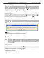
Figure 3-18. [Security flag settings] Area
[Disable Chip Erase] check box
If this check box is selected, the [Erase] command will be disabled for the entire area of the flash memory in the
target device. If this check box is selected, the following dialog box appears.
Figure 3-19. [Disable Chip Erase] Warning Dialog Box
OK
button
The [Disable Chip Erase] check box is selected.
Cancel
button
The [Disable Chip Erase] check box is not selected.
Caution
If the [Disable Chip Erase] function is enabled, erasure for the device can no longer be possible,
moreover, the [Disable Chip Erase] function can no longer be disabled.
[Disable Block Erase] check box
If the [Security] command is executed with this check box selected, the [Erase] command is disabled for all the
selected blocks in the flash memory selected with the [Block] option button in the [Operation Mode] area on the
[Standard] tab in the Device Setup dialog box. This setting is cleared if the [Erase] command is executed with the
[Chip] option button selected in the [Operation Mode] area.
QB-Programmer Programming GUI Preliminary User’s Manual
ZUD-CD-06-0006
29/44
[Disable Program] check box
If the [Security] command is executed with this check box selected, the [Erase] command for all the selected blocks
in the flash memory selected with the [Block] option button in the [Operation Mode] area on the [Standard] tab in the
Device Setup dialog box and the [Program] command is disabled. The [Erase] command is enabled when the
[Chip] option button selected.
This setting is cleared if the [Erase] command is executed with the [Chip] option
button selected in the [Operation Mode] area.
[Disable Read] check box
If the [Security] command is executed with this check box selected, the [Read] command is disabled. The [Erase]
command is enabled when the [Chip] option button selected. This setting is cleared if the [Erase] command is
executed with the [Chip] option button selected in the [Operation Mode] area.
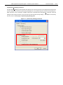
[Disable Boot block cluster reprogramming] check box
If the [Security] command is executed with this item selected, the boot block set in the [End Boot block] drop-down
list is regarded as the last block and then the boot area is set.
If this item is selected, the following dialog box
appears.
Figure 3-20.
OK
[Disable Boot block cluster reprogramming] Warning Dialog Box
button
The [Disable Boot block cluster reprogramming] check box is selected.
Cancel
button
The [Disable Boot block cluster reprogramming] check box is not selected.
Caution
If the [Disable Boot block cluster reprogramming] function is enabled, rewriting of the boot area
and execution the [Erase] command with the [Chip] option button selected in the [Operation
Mode] area can no longer be performed for the device, and the [Disable Chip Erase] function can
no longer be disabled.
[Reset vector] text box
If an address value is input in this text box and then the [Security] command is executed, the reset vector is changed
to the specified address. This setting is cleared if the [Erase] command is executed with the [Chip] option button
selected in the [Operation Mode] area. The initial value is 000000h.
[End Boot block] drop-down list box
Specify the number of the end Boot block. This list shows the block numbers where the flash memory in the target
device is configured.
QB-Programmer Programming GUI Preliminary User’s Manual
ZUD-CD-06-0006
30/44
[Show Address] check box
Specify the display format in the [End Boot block] drop-down list. If this check box is selected, the block address is
displayed. If this check box is cleared, the block number is displayed.
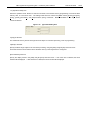
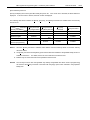
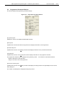
The following table shows whether the [Erase], [Program], and [Read] commands are enabled when each security
function is set.
Command
Security Function
[Erase] Command
[Erase] Command
[Program]
with [Chip] Selected
with [Block] Selected
Command
Disable Chip Erase
Disable Block Erase
Enabled
Disable Program
Enabled
Disable Read
Enabled
Disable Boot block
cluster reprogramming
[Read] Command
EnabledNote 1
Enabled
Enabled
Enabled
Enabled
EnabledNote 2
Note 3
Enabled
Enabled
EnabledNote 3
Enabled
Notes 1. Since the [Erase] command is disabled, data different from that already written to the flash memory
cannot be written.
2. The [Erase] command with the [Block] option button selected is disabled if the [Disable Read] function is
enabled in the device. For details, refer to the user's manual for the device used.
3. Enabled only for areas other than those specified as the boot area.
Remark
The security functions other than [Disable Chip Erase] and [Disable Boot block cluster reprogramming]
are cleared if the [Erase] command is executed with the [Chip] option button selected in the [Operation
Mode] area.
QB-Programmer Programming GUI Preliminary User’s Manual
3.2.3
ZUD-CD-06-0006
[Help] menu
The following pull-down menu appears by clicking the [Help] menu.
Figure 3-21. [Help] Menu
(1)
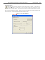
(1) [About QB-Programmer] command
This command opens the following dialog box and shows the versions of the QBP and MINICUBE2 firmware.
Clicking the
OK
button closes this dialog box.
Figure 3-22.
[About QB-Programmer] Dialog Box
31/44
QB-Programmer Programming GUI Preliminary User’s Manual
3.3
ZUD-CD-06-0006
32/44
Toolbar
The commands frequently used with the QBP are displayed on the toolbar. A command can be executed just by
clicking the relevant button. Some commands may be unavailable depending on the parameter selected, or when
the QBP is started for the first time. By pointing to a button with the pointer, the hint for the button is displayed on
the status bar.
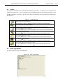
Table 3-1.
Toolbar Buttons
Opens the Device Setup dialog box.
The same action is taken as selecting the [Setup] command on the [Device] menu.
Opens the program file select dialog box.
The same action is taken as selecting the [Load] command on the [File] menu.
Executes the [Blank Check] command.
The same action is taken as selecting the [Blank Check] command on the [Device] menu.
Executes the [Erase] command.
The same action is taken as selecting the [Erase] command on the [Device] menu.
Executes the [Program] command.
The same action is taken as selecting the [Program] command on the [Device] menu.
Executes the [Verify] command.
The same action is taken as selecting the [Verify] command on the [Device] menu.
Executes the [Autoprocedure (EPV)] command.
The same action is taken as selecting the [Autoprocedure (EPV)] command on the
[Device] menu.
3.4
Action Log Window
This window displays the log for the QBP actions.
Figure 3-23.
Action Log Window
QB-Programmer Programming GUI Preliminary User’s Manual
3.5
ZUD-CD-06-0006
33/44
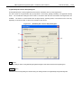
Programmer Parameter Window
This window displays the programming parameter settings.
Figure 3-24.
Programmer Parameter Window
[Programmer] area
Displays the versions of the QBP and MINICUBE2 firmware.
[Device] area
Updated after communication with the target device and displays information on the target device.
[Parameter file] area
Updated after execution of the [Setup] command and displays information on the parameter file selected.
[Load file] area
Updated after execution of the [Load] command and displays information on the program file selected.
The program file checksum result is displayed in the [Chksum] column. The checksum is calculated as follows.
Method: Subtraction (16-bit arithmetic)
Range: From start to end of the program file
[Connection to device] area
Updated after execution of the [Setup] command and displays the settings made on the [Standard] tab in the Device
Setup dialog box.
The number of FLMD0 pulses is displayed in the [Pulse] column.
QB-Programmer Programming GUI Preliminary User’s Manual
3.6
ZUD-CD-06-0006
34/44
Progress Bar
The progress bar shows the progress as a percentage or with a message, when a parameter file or program file is
selected or a command is executed for the target device.
Figure 3-25. Progress Bar
When execution of a command for the target device is completed, the progress bar indicates the result as shown
below.
Table 3-2. Progress Bar Display
Immediately after the QBP is started
A command execution is in progress or a parameter file
or program file is being selected
A command execution or selection of a parameter file or
program file is completed normally
A command execution or selection of a parameter file or
program file is ended abnormally
3.7
Status Bar
By pointing to a command on the menu bar or a button with the pointer, the hint for the command or button is
displayed on the status bar.
Figure 3-26. Status Bar
QB-Programmer Programming GUI Preliminary User’s Manual
ZUD-CD-06-0006
35/44
CHAPTER 4 TROUBLESHOOTING
This chapter explains the troubleshooting.
Remark
Using the MINICUBE2 self-testing tool, the user can find out why the QBP does not operate normally,
such as a defect in MINICUBE2, or problems in other hardware. For the usage of the tool, refer to the
MINICUBE2 Self-Testing Tool User’s Manual.
4.1
Problems During Startup
This section explains the troubleshooting for problems that may occur from software installation to startup.
(1) When MINICUBE2 is connected to the host machine via a USB interface, the driver is not recognized by
Plug and Play.
[Cause]
The USB connector may not be inserted properly into the USB port of the host machine.
[Action]
Check that the USB connector is fully inserted into the USB port of the host machine.
Alternatively, disconnect the USB connector, then insert the USB connector again after a while.
(2) The USB driver file cannot be found at a specified location.
[Cause]
The USB driver may not have been installed normally.
[Action]
Refer to CHAPTER 2 SOFTWARE INSTALLATION and reinstall the USB driver.
If the file is requested by Plug and Play, specify the following path for the USB driver.
C:\Program Files\NEC Electronics Tools\MQB2ALL
(3) MINICUBE2 is connected to the host machine but the Power LED on MINICUBE2 is not turned on.
[Cause]
The USB port of MINICUBE2 or the host machine may have a defect.
[Action]
Check a defect of MINICUBE2 using the MINICUBE2 self-testing tool. If a defect is found, consider repair. If
there is no defect, try connecting MINICUBE2 to another machine.
(4) The “Add New Hardware Wizard” screen appears when MINICUBE2 is connected with the host machine.
[Cause]
If the USB connector of MINICUBE2 is not inserted into the USB port during installation but into another USB
port, MINICUBE2 may be recognized as a new hardware item.
[Action]
Select “Search for a suitable driver for my device (recommended)” and install the USB driver.
QB-Programmer Programming GUI Preliminary User’s Manual
4.2
ZUD-CD-06-0006
36/44
Problems During Operation
This section explains the troubleshooting for problems that may occur during operation.
Remark For causes and actions for the messages displayed in the error/warning dialog box and action log window,
refer to APPENDIX A MESSAGES.
(1) “(E0001): USB host connection failed.” is displayed in the action log window.
[Cause 1]
The USB cable may not be connected properly or the USB driver may not have been installed normally.
[Action 1]
Refer to 4.1 Problems During Startup and take an appropriate action.
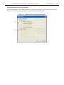
[Cause 2]
When “NECPCIF” is expanded in the Device Manager, “NEC Electronics IE-PC Interface [MINICUBE2 USB]”
is not displayed. Alternatively, the “!” or “×” is prefixed.
[Action 2]
<1> With MINICUBE2 connected to the host machine, right-click the driver marked with the “!” or “×”, and then
click [Uninstall] on the shortcut menu.
<2> Execute [Scan for hardware changes] in the Device Manager.
<3> Reinstall the USB driver by Plug and Play.
[Cause 3]
MINICUBE2 may not have been recognized (when connected via USB hub).
[Action 3]
Try the following.
<1> Disconnect the USB cable and then reconnect it.
<2> Connect the USB connector to another port on the USB hub.
<3> If the above measures do not resolve the problem, do not use the USB hub but directly connect the USB
connector to the USB port of the host machine main unit.
QB-Programmer Programming GUI Preliminary User’s Manual
ZUD-CD-06-0006
37/44
(2) The following message is displayed in the action log window and the flash memory programming mode
cannot be entered.
(E2001) No response from Target Device. (FLMD) ← When UART is selected
(E2002) No response from Target Device. (RESET) ← When UART is selected
(E2003) No response from Target Device. (FREQ) ← When UART is selected
(E9004) Wait status timeout. ← When SIO-H/S is selected
[Cause 1]
The mode select switch that is used to select the target device may be set incorrectly.
[Action 1]
Confirm the target device and the mode select switch setting.
[Cause 2]
The 78K0-OCD board may be connected.
[Action 2]
Remove the 78K0-OCD board.
[Cause 3]
The connection between the target cable and target system may be wrong.
[Action 3]
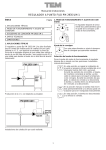
<1> Connect the TxD and RxD signals from MINICUBE2 with TxD (SO) and RxD (SI) of the target device so
that signal input/output are consistent.
MINICUBE2
Target device
TxD
TxD (SO)
RxD
RxD (SI)
<2> The signal lines used for programming must be isolated from other devices, using jumper switches or the
like; otherwise, malfunction may occur.
[Cause 4]
The parameter file selected in the [Parameter file] area on the [Standard] tab in the Device Setup dialog box
may not be correct.
[Action 4]
Use the parameter file that supports the target device.
For details on parameter files, refer to 1.3 Supported Devices and 3.2.2 (10) (a) <1> [Parameter file] area.
[Cause 5]
No clock may be able to be supplied to the target device.
[Action 5]
<1> Check the settings in the [Supply Oscillator] area on the [Standard] tab in the Device Setup dialog box.
For the correct settings, supplementary for the parameter file.
<2> Check the clock supply on the target system.
QB-Programmer Programming GUI Preliminary User’s Manual
ZUD-CD-06-0006
38/44
[Cause 6]
Power may not be supplied normally to the target device.
[Action 6]
<1> Check the power select switch setting.
<2> Check that the power is supplied on the target system.
If the power select switch is set to “3” or “5”, the
power supply is 100 mA max., so a power shortage may occur.
In such a case, set the power select
switch to “T” and then supply power from the target system.
[Cause 7]
When using a 78K0S device, a wrong connection procedure may have been implemented.
[Action 7]
When using a device that uses the program file in which “use the RESET pin as the input-only port (P34)” is
set by the option byte, if power is supplied to the target system before the target cable is connected to the
target system, the flash memory programming mode cannot be entered. Connect the target cable to the
target system in accordance with the procedure and then supply power to the target system.
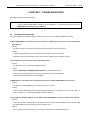
(3) The following message is displayed in the action log window and normal communication is not
performed in the flash memory programming mode.
(E2004) Communication failure or timeout.
[Cause 1]
The clock or power supply may not be stable.
[Action 1]
Confirm that the clock or power is stably supplied on the target system.
[Cause 2]
Communication may not be stable.
[Action 2]
Confirm that MINICUBE2 and the target system are properly connected.
Confirm that unused pins are
properly handled. Confirm that the correct clock and communication rate are selected. Stable programming
may be achieved by setting a lower value for the clock or communication rate.
QB-Programmer Programming GUI Preliminary User’s Manual
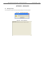
APPENDIX A MESSAGES
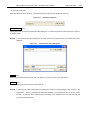
A.1
Message Format
The message will be output for both the error/warning dialog box and action log window.
Figure A-1.
Error/Warning Dialog Box
Figure A-2.
Action Log Window
ZUD-CD-06-0006
39/44
QB-Programmer Programming GUI Preliminary User’s Manual
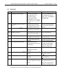
A.2
ZUD-CD-06-0006
40/44
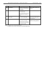
Messages
No.
E0001
Message
Cause
USB host connection failed.
Note 1
Action
Possible causes may be:
Check if the USB driver has
The USB driver is not
been installed normally. For
recognized normally.
details, refer to 4.1 Problems
Communication failed.
During Startup.
MINICUBE2 is not connected.
The USB driver is not installed
normally.
E0002
MINICUBE2 Firmware version too
old.
E0003
Note 1
Note 2
Load File not found.
The QBP does not operate
Download the latest firmware
normally because the version of
from the website (ODS) and
MINICUBE2 firmware is old.
update it.
The program file stored in the
Select a program file.
qbp.ini file cannot be loaded.
E0004
PRM File not found.Note 2
The parameter file stored in the
Select a parameter file.
qbp.ini file cannot be loaded.
E0005
E1001
E1002
QBP already started.Note 1
Note 2
Invalid Parameter File.
Not supported Parameter File.
An attempt was made to start
The QBP cannot be started
the QBP for the second time.
while it is running.
An invalid parameter file was
Download the latest parameter
selected.
file from the website (ODS).
A parameter file with an
Download the latest parameter
unsupported file format version
file, QBP, and MINICUBE2
was selected.
firmware from the website
(ODS) and update them.
E1003
Invalid Load File.
An unsupported format or
Select a relevant program file.
illegal program file was
selected.
E1004
E1005
E1006
Note 2
Not specify Parameter File.
Not specify Load File.Note 2
No parameter file has been
Select a parameter file using
loaded.
the [Setup] command.
No program file has been
Select a program file using the
selected.
[Load] command.
Illegal Supply Oscillator setting.Note 1 The wrong frequency is set for
See the device manual, confirm
the clock supplied to the target
the selectable frequency, and
device.
then set the correct value for
frequency and multiply ratio.
Notes 1. Displayed only in error/warning dialog boxes.
2. Displayed only in both action log window and error/warning dialog boxes.
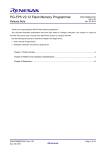
QB-Programmer Programming GUI Preliminary User’s Manual
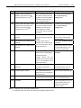
No.
E1007
Message
ZUD-CD-06-0006
Cause
Action
Caution: When ’Chip Erase’ is
This is a warning output when
For details, refer to 3.2.2 (10)
disable, chip cannot be erased
the security function cannot be
(b) <2> [Security flag
disabled if “Chip erase disable”
settings] area.
Note 1
and programmed any more!
41/44
is enabled, because the chip
can no longer be erased.
E1008
Caution: When ’Boot block cluster
This is a warning output when
For details, refer to 3.2.2 (10)
reprogramming’ is disable, boot
the security function cannot be
(b) <2> [Security flag
block cannot be erased and
disabled if “boot block area
settings] area.
Note 1
rewrite disable” is enabled,
programmed any more!
because the chip can no longer
be erased.
E2001
E2002
E2003
No response from Target Device.
The flash memory
MINICUBE2 may have hung,
(FLMD)
programming mode cannot be
disconnect the USB interface
entered.
and reconnect it.
No response from Target Device.
Possible causes may be:
Refer to 4.2 Problems During
(RESET)
unstable clock or power supply,
Operation.
No response from Target Device.
(FREQ)
error in communication line, or
target device defect.
See the device manual, confirm
the selectable frequency, and
then set the correct value.
E2004
Communication failure or timeout.
Normal communication is not
Refer to 4.2 Problems During
performed in the flash memory
Operation.
programming mode.
Possible
causes
may
be:
unstable clock or power supply,
error in communication line, or
target device defect.
E2005
E2006
Synchronization failure for
A baud rate that is not
See the device manual, confirm
baudrate.
supported by the device is
the selectable baud rate, and
selected.
then set the correct value.
The specified parameter file
Select a relevant parameter file.
Invalid Signature reading.
differs from the one specified in
the target device.
E2007
E2008
Invalid parameter file version.
Not Blank.
The versions of the selected
Download the latest parameter
parameter file and device differ.
file from the website (ODS).
The flash memory is not blank.
Before programming, be sure to
erase the flash memory and
make sure that the flash
memory is blank.
Notes 1. Displayed only in error/warning dialog boxes.
2. Displayed only in both action log window and error/warning dialog boxes.
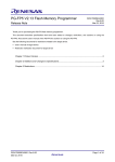
QB-Programmer Programming GUI Preliminary User’s Manual
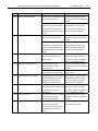
No.
E2009
Message
Erasing operation failed.
ZUD-CD-06-0006
Cause
42/44
Action
Erasure may be impossible due
The device may have a defect,
to a flash memory defect.
so replace it with a non-defective
sample.
With the 78K0S, the specified
Some security functions cannot
command may not be enabled
be disabled by executing chip
because security settings have
erase. For details, refer to the
already been made on the target
manual for the target device.
device.
E2010
Programming operation failed.
Programming may be impossible
The device may have a defect,
due to a flash memory defect.
so replace it with a non-defective
sample.
With the 78K0S, the specified
Some security functions cannot
command may not be enabled
be disabled by executing chip
because security settings have
erase. For details, refer to the
already been made on the target
manual for the target device.
device.
E2011
Verifying operation failed.
Data of the program file may
Reexecute EPV. If the same
differ from that written to the
error occurs again, the device
target device.
may have a defect, so replace it
with a non-defective sample.
E2012
E2013
E2014
E2015
E2016
Security flag setting failed.
Protection by security setting.
Checksum verification failed.
Retry status over.
Illegal status from device.
Security setting may be
The device may have a defect,
impossible due to a flash
so replace it with a non-defective
memory defect.
sample.
Additional security setting may
Refer to the manual for the
be impossible in some devices.
target device.
The specified command may not
Some security functions cannot
be executed because security
be disabled by executing chip
settings have already been
erase. For details, refer to the
enabled on the target device.
manual for the target device.
With the 78K0S, the program
Reexecute EPV. If the same
code written to the target device
error occurs again, the device
may differ from that of the
may have a defect, so replace it
program file.
with a non-defective sample.
The retry count for the command
The device may have a defect,
performed for the device
so replace it with a non-defective
exceeded the upper limit.
sample.
An illegal status code was
The device may have hung, so
returned from the device.
reexecute the command.
The communication line may be
unstable due to an external
factor.
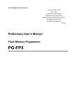
QB-Programmer Programming GUI Preliminary User’s Manual
No.
Message
E9001
Note 2
Not Initialized.
ZUD-CD-06-0006
Cause
43/44
Action
Acquisition of work memory at
Start the QBP in another host
startup failed, or sled processing
machine.
startup failed.
E9002
Illegal parameter.
Command parameter error was
Check the communication line.
returned from F/W.
The communication line may be
unstable due to an external
factor.
E9003
Control failed. Please restart the
An unexpected error code is
MINICUBE2 may have hung,
MINICUBE2.
returned from MINICUBE2.
disconnect the USB interface
and reconnect it.
E9004
Wait status timeout.
Wait of MINICUBE2 for the
For details, refer to 4.2
device timed out. Possible
Problems During Operation.
causes may be: incorrect wiring,
incorrect clock or power supply,
or target device defect.
Notes 1. Displayed only in error/warning dialog boxes.
2. Displayed only in both action log window and error/warning dialog boxes.
QB-Programmer Programming GUI Preliminary User’s Manual
APPENDIX B REVISION HISTORY
Document Number
ZUD-CD-06-0006
Issued on
March 6, 2006
Description
Newly created.
ZUD-CD-06-0006
44/44