1
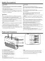
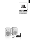
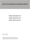
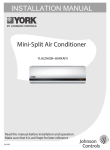
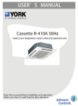
USER’S MANUAL
Floor Ceiling Inverter Indoor R-410A 50/60HZ
YHFJXH(012-024)BAM(R)- -FX
Read this manual before installation and operation
Make sure that it is well kept for later reference
0150509250
Cautions
Safety Precautions
Parts and Functions
Operation
Cleaning and Care
Operation Tips
Troubleshooting
Installation Procedure
Test Run
3
4
4
6
8
8
9
11
17
English
Contents
Cautions
tubes with sharp or pointed items, crushing or twisting any
tubes, or scraping the coatings off the surfaces. If the
refrigerant spurts out and gets into eyes, it may result in
serious eye injuries.
Do not obstruct or cover the ventilation grille of the air
conditioner. Do not put fingers or any other things into the
inlet/outlet and swing louver.
Do not allow children to play with the air conditioner. In no
case should children be allowed to sit on the outdoor unit.
When the indoor unit is turned on, the PCB will test if swing
motor is O.K., and then fan motor will start up.So there is a
few seconds to wait.
In cooling mode,the flaps will swing automatically to a fixed
position for anti-condensating.
This appliance is not intended for use by persons (including
children) with reducedphysical, sensory or mental capabilities,
or lack of experience and knowledge, unless they have been
given supervision or instruction concerning use of the
appliance by a person responsible for their safety.
Children should be supervised to ensure that they do not play
with the appliance.
Disposal of the old air conditioner
Before disposing an old air conditioner that goes out of use,
please make sure it's inoperative and safe. Unplug the air
conditioner in order to avoid the risk of child entrapment.
It must be noticed that air conditioner system contains
refrigerants, which require specialized waste disposal. The
valuable materials contained in a air conditioner can be
recycled. Contact your local waste disposal center for proper
disposal of an old air conditioner and contact your local
authority or your dealer if you have any question. Please
ensure that the pipework of your air conditioner does not get
damaged prior to being picked up by the relevant waste
disposal center, and contribute to environmental awareness
by insisting on an appropriate, anti-pollution method of
disposal.
Disposal of the packaging of your new air conditioner
All the packaging materials employed in the package of your
new air conditioner may be disposed without any danger to
the environment.
The cardboard box may be broken or cut into smaller pieces
and given to a waste paper disposal service. The wrapping
bag made of polyethylene and the polyethylene foam pads
contain no fluorochloric hydrocarbon.
Specifications
The refrigerating circuit is leak-proof.
For all the models in this manual, the all-pole discon-nexion
connection method should be applied in the power supply.
Such means for disconnection must be incorporation in the
fixed wiring.
All these valuable materials may be taken to a waste collecting
center and used again after adequate recycling.
Consult your local authorities for the name and address of the
waste materials collecting centers and waste paper disposal
services nearest to your house.
Cooling
Safety Instructions and Warnings
Heating
Before starting the air conditioner, read the information given
in the User's Guide carefully. The User's Guide contains very
important observations relating to the assembly, operation
and maintenance of the air conditioner.
Indoor temperature
max. DB/WB
min. DB/WB
32/23 C
18/14 C
Outdoor temperature
max. DB/WB
min. DB/WB
46/24 C
18 C
Indoor temperature
max. DB/WB
min. DB/WB
27 C
15 C
Outdoor temperature
max. DB/WB
min. DB/WB
24/18 C
-15 C
If the supply cord is damaged, it must be replaced by the
manufacturer or its service agentor a similar qualified person.
If the fuse on PC board is broken please change it with the
type of T 3.15A /250VAC.
The wiring method should be in line with the local wiring
standard.
The waste battery shall be disposed properly.
The indoor unit installation height is at least 2.5m.
The air breaker and the power switch should installed the
conveniently reachable pleace for user.
The manufacturer does not accept responsibility for any
damages that may arise due to non-observation of the
following instruction.
Damaged air conditioners are not to be put into operation.
In case of doubt, consult your supplier.
Use of the air conditioner is to be carried out in strict
compliance with the relative instructions set forth in the
User's Guide.
Installation shall be done by professional people. Don't install
unit by yourself.
For the purpose of safety, the air conditioner must be properly
grounded in accordance with specifications.
Always remember to unplug the air conditioner before
opening inlet grill. Always grip plug firmly and pull straight
out from the outlet.
All electrical repairs must be carried out by qualified
electricians. Inadequate repairs may result in a major source
of danger for the user of the air conditoiner.
Do not damage any parts of the air conditioner that carry
refrigerant by piercing or perforating the air conditioner's
3
Safety Precautions
CAUTION!
WARNING!
If the power supply cord of this air conditioner is damaged,
it must be replaced by the manufacturer or its authorized
service personnel only.
Use copper wire only. All the cables shall have got the
Local authentication certificate.
The power cable and connecting cable are self-provided.
If the fuse on PC board is broken please change it with
the type of T3.15A/250VAC.
Provide occasional ventilation during use.
Do not direct air flow at fireplaces or heating apparatuses.
Do not place objects on the air conditioner or climb onto
it.
Do not hang objects from the indoor unit.
Do not set flower vases or water containers on top of the
air conditioner.
Do not expose the air conditioner directly to water.
Do not operate the air conditioner with wet hands.
Do not pull power supply cord.
Turn off power source when not using the unit for extended
periods.
Check the condition of the installation stand for damage.
Do not place animals or plants in the direct path of the air
flow.
Do not drink the water drained from the air conditioner.
Do not use in applications involving the storage of foods,
plants or animals, precision equipment or art works.
Do not apply any heavy pressure to radiator fins.
Operate only with air filters installed.
Do not block or cover the intake grill and outlet port.
Ensure that any electronic equipment is at least one metre
away from either the indoor or outdoor unit.
Avoid installing the air conditioner near a fireplace or other
heating apparatuses.
When installing the indoor and outdoor unit, take
precautions to prevent access to infants.
Do not use inflammable gases near the air conditioner.
DANGER!
Do not attempt to install this air conditioner by yourself.
This unit contains no user-serviceable parts. Always
consult authorized service personnel for repairs.
When moving, consult authorized service personnel for
disconnection and installation of the unit.
Do not become excessively chilled by staying for lengthy
periods in the direct cooling airflow.
Do not insert fingers or objects into the outlet port or intake
grills.
Do not start and stop air conditioner operation by connecting
and disconnecting the power supply cord and so on.
Take care not to damage the power supply cord.
In the event of a malfunction (burning smell, etc.), stop
operation immediately, turn off the circuit breaker, and
consult authorized service personnel.
Parts and Functions
10
1
11
3
9
POWER
4
OPER
5
TIMER
6
COMP
7
EMER
2
3
8
(1) Operating Control Panel
Note :
(2) Emergency Switch
For the wired control type unit, the unit state should be
(3) Remote Control Signal Receiver
checked by the wired controller, instead of the remote
(4) Power Indicator Lamp (Red)
receiver. and if you set the TIMER function, the TIMER
(5) Operation Indicator Lamp (Green)
LED on the remote receiver will not be on.
(6) Timer Indicator Lamp (Yellow)
(7) Compressor Run Lamp (Green)
(8) Intake Grill
(9) Air Filter
(10) UP/DOWN Air Direction Flaps
(11) RIGHT/LEFT Air Direction Louvers (behind UP/DOWN Air Direction Flaps)
4
Parts and Functions
Base Operation
Remote controller
SPEED
1. Unit start
Press ON/OFF on the remote controller, unit starts.
2.Select operation mode
Press MODE button. For each press, operation mode
changes as follows:
Remote controller:
AUTO
COOL
DRY
FAN
HEAT
3.Select temp.setting
Press TEMP+ / TEMP- button
time the button is pressed, temp.setting
increase 1oC,if kept depressed, it will increase
rapidly
TEMP- Every time the button is pressed, temp.setting
decrease 1oC,if kept depressed, it will decrease
rapidly
Select a desired temperature.
TEMP+ Every
4.Fan speed selection
Press FAN SPEED button. For each press, fan speed
changes as follows:
Remote controller:
LOW
MED
AUTO
HI
Air conditioner is running under displayed fan speed.
When FAN is set to AUTO, the air conditioner
automatically adjusts the fan speed according to room
temperature.
Operation Remote Display
Controller Board
Mode
AUTO
COOL
according to room temperature.
DRY
In DRY mode, when room temperature becomes
lower than temp.setting+2 oC,unit will run intermittently
at LOW speed regardless of FAN setting.
FAN
In FAN operation mode, the unit will not operate in
COOL or HEAT mode but only in FAN mode ,AUTO is
not available in FAN mode.And temp.setting is disabled.
In FAN mode,SLEEP operation is not available.
HEAT
5
Note
Under the mode of auto operation, air conditioner will
automatically select Cool or Heat operation according
to room temperature. When FAN is set to AUTO, the
air conditioner automatically adjusts the fan speed
Operation
Sleep Operation
3. In AUTO mode
The unit operaters in corresponding sleep mode
adapted to the automatically selected operation
mode.
Before going to bed,you can simply press the SLEEP
button and unit will operate in SLEEP mode and bring
you a sound sleep.
4. In FAN mode
It has no SLEEP function.
5.Set the wind speed change when sleeping
If the wind speed is high or middle before
setting for the sleep, set for lowing the wind
speed after sleeping.
If it is low wind, no change.
Note
When TIMER function is set, the sleeping function
can't be set up .After the sleeping function is set up ,
if user resets TIMER function, the sleeping function
will be cancelled;the machine will be in the state of
timing-on.
Use of SLEEP function
After the unit starts,set the operation status,
then press SLEEP button before which the
clock must be adjusted and time being set.
Operation Mode
1. In COOL,DRY mode
POWER/SOFT Operation
1 hours after SLEEP mode starts,temp.will become
1OC higher than temp.setting.After another 1 hours,
temp.rises by 1OC futher.The unit will run for further
6 hours then stops Temp. is higher than temp.
setting so that room temperature won
for
yourlow
sleep.
be too
SLEEP operation starts
(1) POWER Operation
When you need rapid heating or cooling, you can use this
function. In COOL mode, fan speed automatically takes
high speed of AUTO fan mode. In HEAT mode, fan speed
automatically takes medial speed of AUTO fan mode.
(2) SOFT Operation
You can use this function when silence is needed for
rest or reading. In SOFT operation mode, fan speed
SLEEP operation stops
Approx.6hrs
1 hr
automatically takes low speed of AUTO fan mode.
Note £”
Rises 1OC
During POWER operation, in rapid HEAT or COOL
mode ,
distribution. Long period SOFT operation will cause
effect of not too cool or not too warm.
Rises 1OC
1 hr
Temp.setting
Unit stop
In COOL, DRY mode
To cancel POWER or SOFT operation
Press POWER/SOFT button again ,POWER or SOFT
disappears.
2. In HEAT mode
1 hours after SLEEP mode starts,temp will
become 2 OC lower than temp.setting.After
another 1 hours,temp decrease by 2 OC
futher.After more another 3hours,temp.rises
by 1OC futher.The unit will run for further 3
hours then stops.Temp.is lower than temp.
setting so that room temperature won
too
be high for your sleep.
Temp.setting
1 hr
NOTE:
Cooling only unit do not have displays and functions
related with heating.
Unit stop
Decreases 2OC
1 hr
Decreases 2OC
3 hrs
3 hrs
SLEEP
operation starts
Rises 1OC
SLEEP
operation stops
In HEAT mode
6
6:,1*
ķ
ĸ
Ĺ
ĺ
Ļ
ľ
Ľ
ļ
Note: Postion ĸĹ are null for this model 7
Cleaning and Care
CAUTION:
Before cleaning the air conditioner, be sure to turn it off and disconnect the Power Supply Cord.
Be sure the Intake Grill is installed securely.
When removing and replacing the air filters, be sure not to touch the heat exchanger, or personal injury may result.
Cleaning the Air Filter
1. Open the Intake Grill
Pull out both sides and the center of the Intake Grill.
Arm
2. Pull the Air Filters upward to remove them
Push the Air Filter handles away from the Intake Grille in
the direction as illustrated, then pull out Air Filters.
3. Clean the Air Filters
Remove the dust from the Air Filters by vacuum cleaner
or washing them. After washing, allow the Air Filters to
dry thoroughly in an area protected from sunlight.
Side Panel
Hook
About 30 mm
Notch
Arm
Intake Grill
Air Filter
Bracket
Air Filter
(Figure 1)
4. Re-attach the Air Filters to the Intake Grill
(1)The Filters fit onto the inside of the intake Grill.(Figure 1)
(2)The bottom edges of the Air Filters should fit into the
filter brackets. (Figure 1)
(3)The Air Filters should be pushed down so that their top
edges fit under the projections at the top of the Intake Grill.
(Figure 2)
Base
Handle
(Figure 2)
Filter bracket
5. Close the intake grill
Push in both sides and the center of the Intake Grill.
Dust can be cleaned from the Air Filter either with a vacuum cleaner, or by washing the filter in a solution of mild detergent
and warm water. If you wash the filter, be sure to allow it to dry thoroughly in a shady place before reinstalling.
If dirt is allowed to accumulate on the Air Filter, air flow will be reduced, operating efficiency lowers and noise increases.
During periods of normal use, the Air Filters should be cleaned every two weeks.
Operation Tips
Instructions relating to heating are applicable only to "HEAT & COOL TYPE"
Heating Performance
This air conditioner operates on the heat-pump principle, absorbing heat from outdoor air and transferring that heat indoors.
As a result, the operating performance is reduced as outdoor air temperature drops. If you feel that insufficient heating
perfomance is being produced, we recommend you use this air conditioner in conjunction with another kind of
heating appliance.
Heat-pump air conditioners heat your entire room by recirculating air throughout the room, with the result that some time
may be required after first starting the air conditioner until the room is heated.
Microcomputer-controlled Automatic Defrosting
When using the Heating mode under conditions of low outdoor air temperature high humidity, frost may form on the outdoor
unit, resulting in reduced operating performance.
In order to prevent this kind of reduced performance, this unit is equipped with a Microcomputer-controlled Automatic
Defrosting function. If frost forms, the air conditioner will temporarily stop, and the defrosting circuit will operate briefly (for
about 7 to 15 minutes).
8
Troubleshooting
Followings are not problems
Sound of water flowing is not a problem.
During unit operation or at stop, a swishing or gurgling noise may be heard.
This noise is generated by refrigerant flowing in the system.
Sound of cracking is heard.
During unit operation, a cracking noise may be heard.
This noise is generated by the casing expanding or shrinking because of
temperature changes.
Smell are generated.
This is because the system circulates smells from the interior air such as
the smell of cigarettes or the painting on the furniture.
During operation, white fog or steam
comes out from the indoor unit.
When unit is running at places like restaurant, etc. where dense edible oil
fumes always exist, this will happen.
In cooling operation, unit switches to
blowing operation.
To prevent frost from accumulating on indoor heat exchanger, unit will switch
to blowing operation for a while then resume cooling operation.
Unit will not restart after stop.
Though ON/OFF button is set to ON, the unit won't
resume cooling, dry or heating operation in 3 min
after it is stopped, this is because of
3-min-delay protection circuit.
Won't start?
Please wait 3 minutes
No outlet air or fan speed can't be changed
in dry mode.
Unit will reduce fan speed repeatedly and automatically if room temp. is
too low in dry operation.
In heating operation, water or steam
are blown out of outdoor unit.
This occurs when frost accumulated on the outdoor unit is removed (during
defrosting operation).
In heating operation, indoor fan won't stop
even if unit is stopped.
After unit stop, indoor fan will go on running until indoor unit cools down.
Before ask for services, please first check your unit against the following.
Air conditioner won't start.
Is power supply switch turned on?
Is city power supply normal?
Is leakage current breaker activated?
This is very dangerous, please
disconnect power supply immediately
and contact your dealer.
Power
failure?
Power supply switch is not set at ON.
Poor cooling or heating
Are operation control adjusted
correctly as specified?
Is air filter too dirty?
Proper
temp
Are horizontal louvers at up position
(in heating mode)?
Any doors or windows left open?
9
Are there any obstacles in inlet or
outlet grill?
Troubleshooting
Poor cooling
Is there any direct sunlight in the room?
If there are unexpected heat sources
in the room?
Too many people in the room?
Cold air blows out (in heating mode). Is air conditioner in standby condition in heating mode?
If your unit still can't work properly after above mentioned checks, or following problems occur, please stop it immediately
and contact your dealer.
Fuses or circuit breakers often blow out.
Water comes out in cooling/dry operation.
Operation is abnormal or sound is heard.
When failure happens,the fan of indoor unit stop running.
For indoor failure, only running LED of remote receiver will indicate,
For outdoor failure, timer LED and running LED will indicate .timer LED of remote receiver stands for ten's place, and
running LED stands for one's place. Timer LED will flash firstly, 2 seconds later, running LED will flash too.After that
finishes, 4 seconds later, they will flash in turns again. Flash times is the failure of outdoor + 20.
For example,failure code that outdoor is 2, so indoor unit should display 22. As a result, timer LED flashes twice firstly,
then running LED flashes twice,But when outdoor failure LED flash 20,the indoor unit will flash 42,it's a special.
Ta: ambient temperature sensor
Tm: coil temperature sensor
=^a cWT ^dcS^^a UPX[daT X]SXRPcTS Qh cWT X]S^^a d]Xc _[TPbT aTUTa c^ cWT ^dcS^^a UPX[daT R^ST [Xbc
10
Installation Procedure
Please ask the dealer or specialist to install, never try by the SELECTING THE MOUNTING POSITION
users themselves. After the installation please be sure of the Decide the mounting position with the customer as
following conditions.
follows:
WARNING:
(1) Install the indoor unit level on a strong wall, floor, ceiling
Please call dealer to install the air-conditioner.
which is not subject to vibration.
Incorrect installation may cause water leaking, shock and (2) The inlet and outlet ports should not be obstructed.The
fire hazard.
air should be able to blow all over the room.
(3) Install the unit near an electric outlet or special branch
CAUTION:
circuit.
Air-conditioner can't be installed in the environment
(4) Do not install the unit where it will be exposed to direct
with inflammable gases because the inflammable gases
sunlight.
near air-conditioner may cause fire hazard.
(5) Install the unit where connection to the outdoor unit is
Installed electrical-leaking circuit breaker.
easy.
It easily cause electrical shock without circuit breaker.
(6) Install the unit where the drain pipe can be easily installed.
Connect earthing wire.
(7) Take servicing etc. into consideration and leave the
Earthing wire should not be connected to the gas pipe, water spaces shown in the figure below. Also install the unit where
pipe, lightning rod or phone line, incorrect earthing may
the filter can be removed.
cause shock.
Use discharge pipe correctly to ensure efficient
WARNING:
discharge.
Install at a place that can withstand the weight of the indoor and
Incorrect pipe use may cause water leaking.
outdoor units and install positively so that the units will not topple
Earthing
or fall.
Wiring
Air-conditioner should be equipped with special power supply
CAUTION:
wire.
(1)Do not install where there is the danger of combustible gas
Location
leakage.
(2)Do not install near heat sources.
(3)If children under 10 years old may approach the unit, take
preventive measures so that they cannot reach the unit.
Air-conditioner should be located in well-vented and easily
accessible place.
Air-conditioner should not be located in the following places:
(1) Places with machine oils or other oil vapours.
(2) Seaside with high salt content in the air.
(3) Near hot spring with high content of sulfide gases.
(4) Area with frequent fluctuation of voltage e.g. factory,
etc.
(5) In vehicles or ships.
(6) Kitchen with heavy oil vapour or humidity.
(7) Near the machine emitting electric-magnetic waves.
(8) Places with acid, alkali vapour.
Choose the following locations:
(1) Capable of supporting air conditioner weight, don't
increase operating noise and vibration.
(2) Hot vapour from outdoor unit outlet and operating noise
don't disturb neighbour.
(3) No obstacles around the outdoor unit outlet.
TV, radio, acoustic appliances etc. are at least 1 m far away
from the indoor unit, outdoor unit, power supply wire,
connecting wire, pipes, otherwise images may be disturbed
or noises be created.
As required, take measures against heavy snow.
Under ceiling
Left
30 cm
or more
Floor console
Ceiling
Drain hose
Saddle (L.S) with screws
Piping hole cover
Heat insulation material
Left
30 cm
or more
2 cm
or more
Outdoor unit
Plastic clamp
Putty
Indoor unit
11
1.5m
1.5m
INSTALLATION PARTS
The following installation parts are optional parts. Use them
as required.
Optional parts
Adhesive tape
may be difference
Right
Indoor unit
Right
1.5m
30 cm
or more
Installation Procedure
PREPARING INDOOR UNIT INSTALLATION
Remove the intake grill
Open the intake grill and remove the three or four or six screws.
Note:
The main unit can be wired before the indoor unit is installed.
Select the most appropriate installation order.
Intake grill
Fig. 1
A.FLOOR CONSOLE TYPE
1.Drilling for piping
Select piping and drain directions. The piping and drain can be made
in three directions as shown in the Fig.1.
rear
right
down
The drain hose can be connected to either the left or right side. (Fig.2)
Fig. 2
Drain hose (Left side)
When the directions are selected, drill a 7 cm dia. hole on the wall so
that the hole is tilted downward toward the outdoor for smooth water
flow. When the pipe is led out from the rear, make a hole at the position
shown in Fig.3.
Drain hose (Right side)
Fig. 3
Wall
6mm
7cm
Indoor unit
When installing set to wall, install the accessory wall
bracket at the position shown in Fig. 4, and mount the
set to it.
outdoor unit
Fig. 4
99cm
50cm
24.5cm
Wall bracket
7cm hole
3.5cm hole
12.5cm
2. Installing drain hose
Select whether the drain hose will be
connected to the left or right side (Fig.2). Insert
the drain hose into the drain pan, then secure
the drain hose with a nylon fastener (Fig.5).
Wrap the insulation (drain hose) around the drain
hose connection. (Fig.6)
Fig. 5
6.5cm
53cm
4.5cm
65.5cm
Side of set
6.5cm
10cm
Drain pan
Nylon fastener
Drain hose
Fig. 6
Drain pan
Drain hose
12
Insulation
(Drain hose)
Installation Procedure
Be sure to arrange the drain hose correctly so that it is
leveled lower than the drain hose connecting port of
the indoor unit. (Fig.7)
NO
OK
Fig.7
Arrange the drain hose
lower than this portion.
CAUTION:
Do not install the unit drain hose side is too high.
Height A should be less than 5 mm.(Fig.8)
NO
Drain hose
Fig.8
Drain hose
A
B. UNDER CEILING TYPE
Using the installation template, drill holes for
piping and anchor bolts(for holes).(Fig.9)
Fig.9
A
900m
Drilling position
for anchor bolt
Installation
template
200m
Ceilling
Wall
Drilling position
for piping
1.Drilling for piping
Select piping and drain directions. (Fig.10)
Fig. 10
Rear (Install the drain
hose in the direction.)
CAUTION:
Install the drain hose at the rear. It should not be
installed on the top or right side.
2.Drilling holes for anchor bolts and installing the
anchor bolts
With a concrete drill, drill four 12.7 mm dia. Holes.
(Fig.12)
Insert the anchor bolts into the drilled holes, and drive
the pins completely into the anchor bolts with a hammer.
(Fig.13)
Fig.11
Wall
6mm
Fig.12
60 to 70mm
When the directions are selected, drill 80mm and 50mm
or 150mm dia. hole on the wall so that the hole is tilted
downward toward the outdoor for smooth water flow.
(Fig.11)
Right
12.7mm
Fig.13
13
Installation Procedure
3. Installing brackets
Install the brackets with nuts, washers and spring
washers. (Fig.14)
Fig.14A
Bracket (Left)
Spring washer
Special nut
4. Installing indoor unit
Fig.14B
Bracket
Fig.15
Reset the hex bolts as shown in Fig.15.
Hex bolt
8 to 13mm
Indoor unit
Apply the indoor unit to the brackets. (Fig.16)
Now, securely tighten the hex bolts in both sides.
Bracket (Right)
Fig.16
Bolt
Bracket
Indoor unit
5. Installing the drain hose
Select whether the drain hose will be connected to the left or right side.(Fig.2)
Insert the drain hose into the drain pan, then secure the drain hose with a nylon fastener.(Fig.5)
Wrap the insulation (drain hose) around the drain hose connection. (Fig.6)
Be sure to arrange the drain hose correctly so that it is leveled lower than the drain hose connecting port of the indoor
unit. (Fig.17)
Fig.17
Remove the hole cover.
Arrange the drain hose
lower than this portion
Drain hose
NO
OK
When drain hose is arranged backward. Secure the drain hose with the VT wire. (Fig.18)
Fig.18
Piping hole
VT wire hole
VT wire
Base (Bottom)
Intake grill
Pass the drain hose through here
Drain hose
Cut the grill
14
Installation Procedure
CONNECTING THE PIPING
Table 1
1. Flare processing
(1) Cut the connection pipe with pipe cutters so that the
pipe is not deformed.
(2) Holding the pipe downward so that cuttings cannot
enter the pipe, remove the burrs.
(3) Remove the flare nut from the indoor unit pipe and
outdoor unit and assemble as shown in Table1 and
insert the flare nut onto the pipe, and flare with a
flaring tool.
(4) Check if the flared part "L" (Fig.1) is spread uniformly
and that there are no cracks.
Model
12K
18K
24K
Pipe
Diameter of pipe
Liquid pipe
6.35mm (1/4")
Gas pipe
9.52mm (3/8")
Liquid pipe
6.35mm (1/4")
Gas pipe
12.7mm (1/2")
Liquid pipe
9.52mm (3/8")
Gas pipe
15.88mm (5/8")
Pipe
Small pipe
Flare nut
Small (width across flats 22mm)
Large pipe
Large (width across flats 24mm)
Fig.1
Width across flats
L dimension
L
Dimension A (mm)
A
1.0~1.2
1.0~1.2
Pipe expander
1.4~2.2
2. Bending pipes
The pipes are shaped by your hands. Be careful not to
collapse them.
NO
OK
Extend the pipe by unwinding it
ELECTRICAL WIRING
Connect wiring to the terminal blocks
A. For solid core wiring (or F-cable) (Fig.A)
(1) Cut the wire with a wire cutter or wire-cutting pliers, then strip the insulation to about 25mm of the exposed solid wire.
(2) Using a screwdriver, remove the terminal screw(s) on the terminal board.
(3) Using pliers, bend the solid wire to form a loop suitable for the terminal screw.
(4) Shape the loop wire properly, place it on the terminal board and tighten securely with the terminal screw using a screw
driver.
B. For strand wiring (Fig.B)
(1) Cut the wire with a wire cutter or wire-cutting pliers, then strip the insulation to about 10mm of the exposed strand wiring.
(2) Using a screwdriver, remove the terminal screw(s) on the terminal board.
(3) Using a round terminal fastener or pliers, securely clamp a round terminal to each stripped wire end.
(4) Position the round terminal wire, and replace and tighten the terminal screw using a screw driver.
B. Strand wire
Loop
Insulation
Strip 10mm
Strip 25mm
A. Solid wire
Screw with
special washer
Screw with
special washer
Round
terminal
Round
terminal
Terminal
board
Round
terminal
Wire
Wire
Insulation tube
Cord clamp
Fix connection cord and power cable at the cord clamp
After passing the connection cord and power cable through the insulation tube,
fasten it with the cord clamp, as shown right.
Use VW-1, 0.5 to 1.0 mm thick, PVC tube as the insulation tube.
15
Installation Procedure
CAUTION:
Match the terminal block numbers and connection cord colors with those of the outdoor unit. Erroneous wiring may cause
burning of the electric parts.
Connect the connection cords firmly to the terminal block. Imperfect installation may cause a fire.
Always fasten the outside covering of the connection cord with the cord clamp.(If the insulator is chafed, electric leakage
may occur.)
Always connect the ground wire.
Wiring of indoor unit
(1) Remove the electrical component box.
Electrical component box
CAUTION:
Do not remove the screws. If the
screws are removed, the electrical
component box will fall.
Electrical component box
Remove the four tapping screws.
(2) Pull out the electrical component box.
(3) Remove the electrical component box cover.
CAUTION:
Be careful not to pinch the lead wires
between the electrical component box
and base.
Electrical component box
Base
Remove the three tapping screws.
(4) Wiring
1.Remove the cord clamp.
2.Process the end of the connection cords to the
dimensions shown in the right figure.
3.Connect the end of the connection cord fully into the
terminal block.
4.Fasten the connection cord with a cord clamp.
5.Fasten the end of the connection cord with the screw.
Indoor unit
terminal block
Outdoor unit
terminal block
Electrical component box cover
1
2
3
Y/G
1(N) 2(L) 3(C)
Y/G
WARNING:
(1) Always use a special branch circuit and install a special receptacle to supply power to the room air conditioner.
(2) Use a circuit breaker and receptacle matched to the capacity of the room air conditioner.
(3) The circuit breaker is installed in the permanent wiring. Always use a circuit that can trip all the poles of the wiring and
has an isolation distance of at least 3mm between the contacts of each pole.
(4) Perform wiring work in accordance with standards so that the room air conditioner can be operated safely and positively.
(5) Install a leakage circuit breaker in accordance with the related laws and regulations and electric company standards.
CAUTION:
(1) The power source capacity must be the sum of the room air conditioner current and the current of other electrical
appliances. When the current contracted capacity is insufficient, change the contracted capacity.
(2) When the voltage is too low and the air conditioner is difficult to start, contact the power company the voltage raised.
16
Installation Procedure
MOUNT THE COVER PLATE AND THE INTAKE GRILL
1.Mount the cover plate (right)
(1) Cut a pipe exit hole in the right plate. This is only when
the pipe exits from the right side. This operation is not required
when the protrusion is on the top or rear.
(2) Insert the hinges on the bottom of the intake grill into the
holes in the base assembly. Then mount the arms to the
three areas on the top of the intake grill.
Cover plate (right)
(2) Join the cover plate (right) and mount with screws.
31
3. Mount the intake grill.
(1) Cut the right side of the intake grill. This is only when
the pipe exits from the right side
2. Mount the cover plate (left)
Join the cover plate (left) and mount with screws.
Test Run
Check items
1. Indoor unit
Is operation of each button on the remote control unit
normal?
Does each lamp light normally?
Do not air flow direction louvers operate normally?
Is the drain normal?
2. Outdoor unit
Is there any abnormal noise and vibration during operation?
Will noise, wind or drain water from the unit disturb the
neighbors?
Is there any gas leakage?
Customer guidance
Explain the following to the customer in accordance with the
operating manual:
(1) Starting and stopping method, operation switching,
temperature adjustment, timer, air flow switching and other
remote control unit operations.
(2) Air filter removal and cleaning, and how to use air louvers.
(3) Give the operation and installation manuals to the customer.
17
2013 Johnson Controls, Inc.
www.johnsoncontrols.co m
AHFJXHAR--130131
Johnso n Controls reserve the right to change product features without prior notice .