1
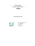
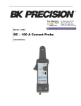
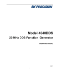
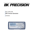
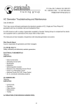
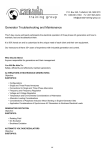
Data sheet
50 MHz Arbitrary Waveform/ Function Generators
Models 4076 & 4079
Common Features & Benefits
■ 14-bit,
125 MSa/s, 4,000 k point Arbitrary
Waveform Generator
■ 50
MHz Sine / 50 MHz Square waveforms
■ Predefined
Pulse, Ramp, Triangle, Noise, Sin
(X)/X, Exponential and Gaussian waveforms
■ AM,
■ 10
FM and FSK modulation
mVpp to 10 Vpp with 1 mVpp settable
amplitude resolution
■ Large
4076
graphical LCD shows a detailed output
waveform representation
■ Fully
programmable markers
■ Fully
protected output
■ Closed
case calibration
■ Arbitrary
waveform editing software included
■ SCPI
compliant command set
■ GPIB
and RS-232 interfaces (standard)
4079
Industry Leading Performance
Dual Channel Model 4079
Models 4076 and 4079 are versatile high performance function/arbitrary waveform generators with the
largest arbitrary memory depth in their class. The generators combine the ability to produce nearly any
conceivable arbitrary waveform with accuracy and precision and a DDS architecture offering easy to use
conventional function generator capabilities. Arbitrary waveforms have 14 bit amplitude resolution,
125 MSa/s sample rate and up to 4,000,000 points length. Waveforms can be output in continuous,
triggered, gated or burst modes. Front panel operation is straightforward and user-friendly. The
instruments can be remotely controlled using SCPI-compliant commands via RS232 or GPIB interface.
■ Both
channels offer full functionality. All wave
form parameters such as frequency, amplitude
and offset can be set independently
■ Synchronize
both output signals to the same
clock signal (external or internal) and precisely
adjust the phase relationship between the two
signals
Extensive features such as internal or external AM, FM and FSK modulation along with versatile sweep
capabilities and variable edge pulse generation make these generators suitable for a wide range of applications including electronic design, sensor simulation, functional test or generation of I/Q modulated signals.
Technical data subject to change
© B&K Precision Corp. 2009
v082009
w w w.bk prec ision.c om
Tel.: 714.921.9095
■ Economical
■ Saves
baseband I/Q signal source
cost and bench space
50 MHz Arbitrary / Function Generators
Models 4076 & 4079
▲ Front panel
Informative
LCD with detailed display of
waveform parameters
Easy-to-use keypad
allows efficient parameter
configuration
Model 4079 allows for both
independent and phase synchronized waveform generation
Intuitive user interface
These Waveform Generators use a menu-driven
front panel keypad and control knob along with
an easy-to-read graphical LCD to adjust all
waveform parameters, which are visible at one
glance. Arbitrary waveform editing and definition
is flexible and easy: Waveforms can be defined
from scratch by entering data point by point, by
loading and modifying predefined built-in
waveforms or by downloading waveforms via the
remote interface, using either the included
arbitrary waveform generation software Wave-X
or a custom program. Standard function
generator waveforms sine, square, ramp and
pulse can be created by pressing a single button.
▲ Rear panel
4079 only
10 MHz external reference
Flexible interface
Built-in 10 MHz external reference is included
at no extra cost (both models).
This input/output let’s you synchronize with
another 4076/4079 generator or to an
external 10 MHz Clock for precise phase
adjustment.
Connect the programmable marker Output to
the Trigger input of additional generators to
create complex polyphase scenarios.
4076 & 4079
2
GPIB & RS-232
interface (standard)
w w w .b k p r ec is i o n .c o m
50 MHz Arbitrary / Function Generators
Models 4076 & 4079
Flexible memory management
Unlike other comparable generators, which
typically contain only a few fixed-size memory
locations for waveform storage, the 4076 and
4079 gives users more freedom - the
4,000,000 point flash memory can be allocated
to one large waveform or up to 50 different
waveforms, each with a customizable length.
Versatile noise generation
In Arb mode you can conveniently add noise to
your waveform directly from the front panel and
precisely adjust the scale of the noise amplitude.
Unlike other generators that only produce a
noise waveform, this feature allows you to
choose between generating a noise waveform or
adding noise to an existing waveform.
Waveform Summing
The Summing Input on the rear panel allows
waveforms from external signal sources to be
summed with the output signal of the 4076 or
4079.
Programmable Markers
Models 4076 and 4079 provide fully programmable markers, allowing you to generate a
positive TTL level output signal at the points
specified by address and length up to 4000
points. This feature is available in Arbitrary mode
and can not be found in other comparable
waveform generators. It could be used for
applications requiring polyphase signal
generation, e.g. simulation of a real world 3
phase AC network where one of the phases is
degraded with spikes or noise.
Generate waveforms with ease
The included PC Software allows you to easily
generate, edit and download custom arbitrary
waveforms.
Generate waveforms by importing a textfile, or
define via freehand, point draw or waveform
math. Waveforms can also be uploaded from the
generator for documentation purposes.
3
w w w .b k p r ec is i o n .c o m
50 MHz Arbitrary / Function Generators
Models 4076 & 4079
Specifications
4076
models
4079
Channels
1 Channel
2 Channels
F r eq ue nc y Ch ar ac te ri stic s
Sine
1 µHz to 50 MHz
Square
1 µHz to 50 MHz
Triangle, Ramp
1 µHz to 5 MHz
Pulse
0.5 mHz to 25 MHz
Accuracy
0.001 % (10 ppm)
Resolution
12 digits or 1 µHz
A r b itr a ry C ha ra ct er is t ics
Built-in Waveforms
Sine, Triangle, Square, Noise, Ramp Up, Ramp
Down, Sine(X)/X, Exponential Up, Exponential
Down, Gaussian
Waveform Length
2 points to 4,000,000 points
Vertical Resolution
14 bits (16,384 levels)
Noise
Add 1% to 100% to output waveform
Sampling Rate
125 MSa/s, Point execution rate adjustable from 8 ns-100 s
Frequency
Accuracy: 0.001% (10 ppm)
Resolution: 4 digits or 1 ps
O u tp u t C ha ra c ter ist ic s
Amplitude Range
10 mV to 10 Vp-p into 50 Ω
Amplitude Resolution
3 digits (1000 counts)
Amplitude Accuracy (1 kHz) ± 1% ± 20 mV of programmed output from
1 V – 10 V
Flatness (relative to 1 kHz) ± 0.1 dB to 10 MHz
± 1 dB to 50 MHz
Offset Range
± 4.99 V into 50 Ω, depending on the
Amplitude setting
Offset Resolution
10 mV with 3 digits resolution
Offset Accuracy
± 1% ± 10 mV into 50 Ω
Output Impedance
50 Ω typical
Output Protection
The instrument’s output is protected against
short circuit or nominal accidental voltages
applied to the main output connector
Filter
9 pole Elliptic and 5 pole Bessel filters
W ave for m Ch ar ac t eri stic s
Harmonic Distortion (sine) DC-20 kHz, -65 dBc
20 kHz-100 kHz, 60 dBc
100 kHz-5 MHz, -45 dBc
5 MHz-50 MHz, -35 dBc
Spurious (sine)
DC-1 MHz
< -65 dBc
Rise/Fall Time (square, pulse) < 6 ns (10% to 90%) at full amplitude into 50 Ω
Variable Duty Cycle
20% to 80% to 10 MHz (square)
40% to 60% to 30 MHz (square)
50% >30 MHz (square)
Variable Symmetry
10%-90% to 5 MHz (triangle)
Symmetry at 50%
< 0.5 %
Linearity (triangle, ramp)
<0.1% of peak output (1 µHz to 250 kHz)
Aberrations
< 3 % of p-p amplitude ± 50 mV
Pulse Width
20 ns to <(Period-20 ns)
(10 ns resolution)
Variable Edge Time
100 ns to Width/0.625 (50 % duty cycle)
10 ns resolution
O p er at ing Mod es
Continuous
Output continuous at programmed parameters
Triggered
Output quiescent until triggered by an internal or
external trigger, then one waveform cycle is generated
to programmed parameters. Up to 20 MHz trigger
rate for ARB waveforms and 10 MHz in DDS mode
Gate
Same as triggered mode, except waveform is
4
Burst
Phase
Trigger Source
executed for the duration of the gate signal. The last
cycle started is completed
2-999,999 cycles
-180 to +180 degrees with 0.1 degree resolution
Trigger source may be internal, external or manual.
Internal trigger rate 0.01 Hz-1 MHz (1 µs – 100 s)
M od ul at ion Ch ar a ct er is ti cs
Amplitude Modulation
Internal
0.01 Hz-20 kHz sine , square or triangle waveform
variable modulation from 0% to 100%
External
5 Vp-p for 100% modulation, 10 kΩ input
impedance, 0.01 Hz – 50 KHz bandwidth
Frequency Modulation
Internal
0.01 Hz-20 kHz sine wave, square or triangle
External
5 Vp-p for 100% deviation, 10 kΩ input impedance
0.01 Hz – 50 kHz bandwidth
FSK
Internal
0.01 Hz to 1 MHz
External
1 MHz max.
S we ep C ha ra c ter is t ics
Sweep Shape
Linear and Logarithmic, up or down
Sweep Time
10 ms to 500 s
Sweep Trigger
internal, external, continuous or burst
Inpu ts a nd Ou tpu ts
Trigger IN
TTL Compatible
Maximum rate 20 MHz
Minimum width 20 ns
Input Impedance10 kΩ nominal
Sync OUT
TTL pulse at programmed frequency, 50 Ω source
impedance
Modulation IN
5 Vp-p for 100% modulation
10 kΩ input impedance
DC to >50 kHz minimum bandwidth
Marker Out
Positive TTL pulse user programmable in Arbitrary
waveform, 50 Ω source impedance
Reference IN-OUT
10 MHz, TTL compatible, input or output, for
external unit synchronization 50 Ω output impedance
and 1 kΩ input
Summing IN
5 Vp-p signal for full scale output, 500 Ω input
impedance
I nt ern al Tri gger
Repetition
1 ms to 100 s
Resolution
4 digits
Accuracy
±0.002%
Ge ner al
Display Resolution
160 x 80 dots LCD
Remote Control Interface
GPIB, RS-232
Store Memory
50 full panel settings at power-off
Dimensions (WxHxD)
8.4(213) x 3.5(88) x 10.8(275) inches (mm)
Weight
Approx. 2.5 kg (5.55 lbs)
Power
100-240 VAC ± 10%, 50 VA max.
Temperature
Operating
0 ºC to + 50 ºC
Non-operating -20 ºC to + 70 ºC
Humidity
95 % RH , 0 ºC to 30 ºC
EMC
According to EN55011 for radiated and conducted
emissions
Electrical Discharge Immunity According to EN55082
Safety Specifications
According to EN61010 , CE approved
Three Year Warranty
Accessories
Supplied: CD containing user manual & Wave-X software, null modem serial
interface cable, power cord
w w w .b k p r ec is i o n .c o m