1
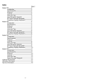
Model 4040DDS
20 MHz DDS Function Generator
OPERATING MANUAL
v092711
1
Model 4040DDS– Operating Manual
Limited Three-Year Warranty
B&K Precision warrants to the original purchaser that its products and the component parts thereof,
will be free from defects in workmanship and materials for a period of three years from date of
purchase from an authorized B&K Precision distributor.
B&K Precision will, without charge, repair or replace, at its option, defective product or component
parts. Returned product must be accompanied by proof of the purchase date in the form of a sales
receipt.
To obtain warranty coverage in the U.S.A., this product must be registered by completing the warranty
registration form on www.bkprecision.com within fifteen (15) days of purchase.
Exclusions: This warranty does not apply in the event of misuse or abuse of the product or as
a result of unauthorized alterations or repairs. The warranty is void if the serial number is
altered, defaced or removed.
B&K Precision shall not be liable for any consequential damages, including without limitation damages
resulting from loss of use. Some states do not allow limitations of incidental or consequential
damages. So the above limitation or exclusion may not apply to you.
This warranty gives you specific rights and you may have other rights, which vary from state-to-state.
Service Information
Warranty Service: Please go to our website, www.bkpreicsion.com & click on the service/repair button to
obtain an RMA #. Return the product in the original packaging with proof of purchase to the address below.
Clearly state in writing the performance problem and return any leads, probes, connectors and accessories that
you are using with the device.
Non-Warranty Service: Please go to our website, www.bkpreicsion.com & click on the service/repair button to
obtain an RMA #. Return the product in the original packaging to the address below. Clearly state in writing the
performance problem and return any leads, probes, connectors and accessories that you are using with the
device. Customers not on open account must include payment in the form of a money order or credit card. For
the most current repair charges please visit www.bkprecision.com and click on “service/repair”.
Return all merchandise to B&K Precision Corp. with pre-paid shipping. The flat-rate repair charge for NonWarranty Service does not include return shipping. Return shipping to locations in North American is included
for Warranty Service. For overnight shipments and non-North American shipping fees please contact B&K
Precision Corp.
B&K Precision
22820 Savi Ranch Parkway
Yorba Linda, CA 92887
www.bkprecision.com
714-921-9095
Include with the returned instrument your complete return shipping address, contact name,
phone number and description of problem.
2
Safety Summary
The following safety precautions apply to both operating and maintenance personnel and must be
observed during all phases of operation, service, and repair of this instrument. Before applying power,
follow the installation instructions and become familiar with the operating instructions for this
instrument.
Failure to comply with these precautions or with specific warnings elsewhere in this manual violates
safety standards of design, manufacture, and intended use of the instrument. B&K Precision
Corporation assumes no liability for a customer’s failure to comply with these requirements. This is a
Safety Class I instrument.
GROUND THE INSTRUMENT
To minimize shock hazard, the instrument chassis and cabinet must be connected to an electrical
ground. This instrument is grounded through the ground conductor of the supplied, three-conductor ac
power cable. The power cable must be plugged into an approved three-conductor electrical outlet. Do
not alter the ground connection. Without the protective ground connection, all accessible conductive
parts (including control knobs) can render an electric shock. The power jack and mating plug of the
power cable meet IEC safety standards.
DO NOT OPERATE IN AN EXPLOSIVE ATMOSPHERE
Do not operate the instrument in the presence of flammable gases or fumes. Operation of any electrical
instrument in such an environment constitutes a definite safety hazard.
KEEP AWAY FROM LIVE CIRCUITS
Instrument covers must not be removed by operating personnel. Component replacement and internal
adjustments must be made by qualified maintenance personnel. Disconnect the power cord before
removing the instrument covers and replacing components. Under certain conditions, even with the
power cable removed, dangerous voltages may exist. To avoid injuries, always disconnect power and
discharge circuits before touching them.
DO NOT SERVICE OR ADJUST ALONE
Do not attempt any internal service or adjustment unless another person, capable of rendering first aid
and resuscitation, is present.
DO NOT SUBSTITUTE PARTS OR MODIFY THE INSTRUMENT
Do not install substitute parts or perform any unauthorized modifications to this instrument. Return the
instrument to TEXIO for service and repair to ensure that safety features are maintained.
WARNINGS AND CAUTIONS
WARNING and CAUTION statements, such as the following examples, denote a hazard and appear
throughout this manual. Follow all instructions contained in these statements.
A WARNING statement calls attention to an operating procedure, practice, or condition, which, if not
followed correctly, could result in injury or death to personnel.
A CAUTION statement calls attention to an operating procedure, practice, or condition, which, if not
followed correctly, could result in damage to or destruction of part or all of the product.
WARNING:
Do not alter the ground connection. Without the protective ground connection, all
accessible conductive parts (including control knobs) can render an electric shock.
The power jack and mating plug of the power cable meet IEC safety standards.
3
Model 4040DDS– Operating Manual
WARNING:
To avoid electrical shock hazard, disconnect power cord before removing covers.
Refer servicing to qualified personnel.
CAUTION:
Before connecting the line cord to the AC mains, check the rear panel AC line
voltage indicator. Applying a line voltage other than the indicated voltage can
destroy the AC line fuses. For continued fire protection, replace fuses only with
those of the specified voltage and current ratings.
CAUTION:
This product uses components which can be damaged by electro-static discharge
(ESD). To avoid damage, be sure to follow proper procedures for handling, storing
and transporting parts and subassemblies which contain ESD-sensitive
components.
4
Contents
Section 1
Section 2
Section 3
Introduction
1.2
Description ................................................................................................................
7
1.3
Specifications ............................................................................................................
7
Installation
2.1
Introduction ...............................................................................................................
9
2.4
Instrument mounting..................................................................................................
9
2.5
Power requirements ...................................................................................................
9
2.6
Grounding requirements ............................................................................................
9
Operating Instructions
3.1
General Description ...................................................................................................
11
3.4
Connectors .................................................................................................................
12
3.6
Function Keys ............................................................................................................
13
3.10
Power-on Settings ......................................................................................................
17
Section 1
5
Model 4040DDS– Operating Manual
Introduction
1.1 Introduction
This manual contains information required to operate the MODEL 4040DDS – 20MHz DDS Function Generator.
This section covers the instrument general description, instrument specifications and characteristics. Please note
that the RS-232 connector on the back of the unit is not to be used as a programming or user interface. It is for
factory use only.
1.2 Description
The MODEL 4040DDS is a versatile high performance function generator that produces Sine, Square and Triangle
signals. Waveforms can be output in continuous, triggered or gated mode. AM and FM modulation combined with
versatile Sweep capabilities make the unit suitable for a wide range of applications.
1.3
MODEL 4040DDS - SPECIFICATIONS
FREQUENCY CHARACTERISTICS (STANDARD WAVEFORMS)
Sine
Square
Triangle , Ramp
Accuracy
Resolution
-
0.1 Hz to 20 MHz
0.1 Hz to 20 MHz
0.1 Hz to 2 MHz
0.01 % (100 ppm)
4 digits or 10 mHz
-
10mV to 10Vp-p into 50 ohms
3 digits (1000 counts)
± 2% ± 20mV of the programmed output from 1.01V- 10V
0.5 dB at 1MHz
1 dB to 20 MHz
± 4.5V into 50 ohms, depending on the Amplitude setting
10 mV with 3 digits resolution
± 2% ± 10mV into 50 ohms
50 ohms
The instrument output is protected against short circuit or accidental
voltage practically available in electronic laboratories, applied to the
main output connector
OUTPUT CHARACTERISTICS
Amplitude Range
Resolution
Amplitude Accuracy
Flatness
Offset Range
Offset Resolution
Offset Accuracy
Output Impedance
Output Protection
WAVEFORM CHARACTERISTICS
Harmonic Distortion
Spurious
Square Rise/Fall Time
Variable Duty Cycle
Symmetry at 50%
-
0-20 KHz
-50 dBc
20 KHz-100 KHz
-45 dBc
100 KHz-1 MHz
-40 dBc
1 MHz-20 MHz
-30 dBc
DC-1MHz <-55 dBc
< 20 ns (10% to 90%) at full amplitude into 50 ohms
20% to 80% to 2 MHz for Square and 10%-90% for Triangle
<1%
6
OPERATING MODES
Continuous
Triggered
-
Gate
-
Trigger Source
-
Output continuous at programmed parameters.
Output quiescent until triggered by an internal or
external trigger, then one waveform cycle is generated to
programmed parameters, up to 2 MHz
Same as triggered mode, except waveform is executed for the
duration of the gate signal. The last cycle started is completed.
Trigger source may be internal, external or manual.
Internal trigger rate 10us to 10s.
MODULATION CHARACTERISTICS
Amplitude Modulation
- Internal:
Sine signal of 1000 Hz
Variable modulation from 0% to 100% in 1% steps.
5 Vp-p for 100% modulation, 10 Kohms input impedance,
DC to 20 KHz bandwidth.
- External:
Frequency Modulation
- Internal:
- External:
Sine signal of 1000 Hz
5 Vp-p for 100% deviation, 10 Kohms input impedance,
DC to 20 KHz bandwidth.
SWEEP CHARACTERISTICS
Sweep Shape:
Sweep Time:
Linear and Logarithmic, up or down
10 ms to 50 s.
INPUTS AND OUTPUTS
Trigger In
Sync Out
Modulation IN
-
TTL compatible.
Max. rate 2MHz.
Minimum width 50ns.
TTL pulse at programmed frequency, 50 ohms source impedance.
5 Vp-p for 100% modulation .
10 KΩ input impedance. Dc to >20 KHz minimum bandwidth.
GENERAL
Dimensions
Weight
-
8.4 inch (213 mm) wide
3.5 inch (88 mm) high
8.3 inch (210 mm) deep
Aprox 2.5 Kg.
Power
- 90V-264V, 30 VA max
Temperature
- Operating - 0ºC to +50ºC, Non-operating - -10ºC to +70ºC
EMC
Electrical Discharge Immunity
Safety Specifications
- According to EN55011 for radiated and conducted emissions.
- According to EN55082
- According to EN61010
NOTE
Specifications are verified according to the performance check procedures in the technical manual.
Specifications not verified in the manual are either explanatory notes or general performance characteristics only.
7
Model 4040DDS– Operating Manual
Section 2
Installation
2.1 Introduction
This section contains installation information, power requirements, initial inspection and signal connections for
MODEL 4040DDS - Function Generator.
2.2 Mechanical Inspection
This instrument was carefully inspected before shipment. Upon receipt inspect the instrument for damage that might
have occurred in transit. If there is damage due to shipping, file a claim with the carrier who transported the unit. The
shipping and packing material should be saved if reshipment is required. If the original container is not to be used,
then use a heavy carton box. Wrap the unit with plastic and place cardboard strips across the face for protection. Use
packing material around all sides of the container and seal it with tape bands. Mark the box "FRAGILE".
2.3 Initial Inspection
After the mechanical inspection, verify the contents of the shipment (accessories and installed options). If the
contents are incomplete, or if the instrument does not pass the specification acceptance tests, notify the local service
center.
2.4 Instrument Mounting
The MODEL 4040DDS - Function Generator is intended for bench use. The instrument includes a front feet tilt
mechanism for optimum panel viewing angle. The instrument does not require special cooling when operated within
conventional temperature limits. The unit can be installed in a closed rack or test station if proper air flow is assured
for removing about 15 W of power dissipation.
2.5 Power Requirements
The MODEL 4040DDS can be operated from any source of 90V to 264V AC, frequency from 48Hz to 66Hz. The
maximum power consumption is 30 VA. Use a slow blow fuse UL/CSA approved of 1A as indicated on the rear
panel of the instrument.
The instrument power fuse is located in the AC input plug. To access the fuse, first disconnect the power cord and
then remove the fuse cartridge.
2.6 Grounding Requirements
For the safety of operating personnel, the instrument must be grounded. The central pin on the AC plug grounds the
instrument when properly connected to the ground wire and plugged into proper receptacle.
8
WARNING
TO AVOID PERSONAL INJURY DUE TO SHOCK, THE THIRD WIRE EARTH GROUND MUST BE
CONTINUOUS TO THE POWER OUTLET. BEFORE CONNECTION TO THE POWER OUTLET,
EXAMINE ALL CABLES AND CONNECTIONS BETWEEN THE UNIT AND THE FACILITY POWER
FOR A CONTINUOUS EARTH GROUND PATH.
THE POWER CABLE MUST MEET IEC SAFETY STANDARDS.
2.7 Signal Connections
Use RG58U 50 Ohm or equivalent coaxial cables for all input and output signals to and from the instrument.
1.4 TECHNICAL SUPPORT
If this product fails to operate upon arrival, contact your B&K PRECISION dealer or the factory to
arrange for service or exchange.
To arrange technical assistance or for service, contact the factory at:
B&K Precision Corp.
22820 Savi Ranch Parkway
Yorba Linda, CA 92887
714-921-9095
www.bkprecision.com
9
Model 4040DDS– Operating Manual
Section 3
Operating Instructions
3.1 General Description
This section describes the displays, controls and connectors of the MODEL 4040DDS - Function Generator.
All controls for the instrument local operation are located on the front panel. The connectors are located on both
front and rear panels.
Figure 3.1 - MODEL 4040DDS Front Panel
1. Power ON-OFF
-Applies and removes AC power to the unit.
2. Display Window
-Displays all instrument data and settings on a LCD.
3. Function Keys
-Select the output waveform, Sine, Square, Triangle or the MODE, SWEEP and
MODULATION..
4. Rotary Knob
-Used to increment/decrement numerical values or to scan
through the possible selections.
5. Modify Keys
-Used to move the cursor (when visible) to either left or right.
10
3.2 Display Window
The MODEL 4040DDS has a graphic LCD display that can display up to 122 x 32 dots. When you power-on the unit
the SINE is selected and its current settings appear in the display. The bottom displays a status line that corresponds
to the function, parameter or mode displayed selected.
3.3 Front Panel Controls
The front-panel controls select, display, and change parameter, function, and mode settings.
Use the rotary input knob and the cursor movement keys to enter data into the waveform generator.
To change a setting:
1. Press the key that leads to a required item.
2. Move cursor using cursor keys to the appropriate position in the numeric field (if applicable).
3. Use the rotary input to change the value of the displayed item. Changes take effect immediately.
The following subsections describe the function of each front panel key and connector.
3.4
Connectors
The function generator has all BNC connectors on the front panel where you can connect coaxial cables. These
coaxial cables serve as carrier lines for input and output signals delivered to and from the function generator.
Output Connector
Use this connector to transfer the main output signal from the function generator.
Trig In Connector
Use this connector to apply an external trigger or gate signal, depending on the waveform generator setting, to the
generator. This connector is also the input to the build-in counter, activated by pressing the COUNT pushbutton.
Sync Out Connector
Use this connector to output a positive TTL sync pulse generated at each waveform cycle.
Modulation In Connector
5V p-p signal for 100% modulation, 10Kohms input impedance with DC - >20 KHz bandwidth.
3.5
Output Connections
The waveform generator output circuits operate as a 50 ohms voltage source working into a 50 ohms load. At higher
frequencies, non terminated or improperly terminated output cause aberrations on the output waveform. In addition,
loads less than 50 ohms reduce the waveform amplitude, while loads more than 50 ohms increase waveform
amplitude.
Excessive distortion or aberrations caused by improper termination are less noticeable at lower frequencies, especially
with sine and triangle waveforms. To ensure waveform integrity, follow these precautions:
1. Use good quality 50 ohms coaxial cable and connectors.
2. Make all connections tight and as short as possible.
11
Model 4040DDS– Operating Manual
3. Use good quality attenuators if it is necessary to reduce waveform amplitudes applied to sensitive circuits.
4. Use termination or impedance-matching devices to avoid reflections.
5. Ensure that attenuators and terminations have adequate power handling capabilities.
If there is a DC voltage across the output load, use a coupling capacitor in series with the load. The time constant of
the coupling capacitor and load must be long enough to maintain pulse flatness.
Impedance Matching
If the waveform generator is driving a high impedance, such as the 1 Mohm input impedance (paralleled by a stated
capacitance) of an oscilloscope vertical input, connect the transmission line to a 50 ohms attenuator, a 50 ohms
termination and to the oscilloscope input. The attenuator isolates the input capacitance of the device and terminates
the waveform generator properly.
3.6 FUNCTION Keys
These keys select the main menus for displaying and changing a parameter, function or mode.
3.6.1 WAVEFORM Keys
The keys select the waveform output and displays the waveform parameters (frequency, amplitude or offset).
The SINE, RAMP and SQUARE pushbuttons select the output waveform. A build-in LED indicates the waveform
selected.
Sine Menu
FREQ button
- (Frequency) Selects and displays the frequency. Change the frequency setting using the cursor
keys and the rotary knob. This pushbutton returns to Frequency display from any other menu
displayed.
AMPL Knob
- Changes the waveform Amplitude.
OFST button
-Selects the Offset parameter. Change the offset by using the cursor keys and Amplitude/Offset
rotary knob. If a certain setting cannot be produced, the waveform generator will display a
“Setting Conflict” message.
Amplitude and Offset Interaction:
Amplitude and offset settings interact and are bound by hardware restrictions. In order to obtain the desired
waveform the following amplitude and offset hardware limitations must be considered:
Offset Menu
12
The offset voltage has three ranges as follows:
Output Voltage Range
Constraints of Amplitude + Offset
1.01 volt to 10.00 volts
(Vp-p)/2 + |offset| <= 5 volts
0.101 volt to 1 volt
(Vp-p)/2 + |offset| <= 0.5 volts
0.010 volt to 0.100 volt
(Vp-p)/2 + |offset| <= 0.05 volts
DUTY button
- When the Square or Triangle waveforms are selected, the variable SYMMETRY is
available. Change the waveform symmetry by using the cursor keys and rotary knob. If a
certain setting cannot be produced, the waveform generator will display a warning message.
Symmetry Menu
3.6.2 MODE Key
Selects the output mode: CONT (Continuous), TRIG (Triggered) and GATE (Gated).
To select the output mode, press MODE. Each additional MODE key operation selects TRIG, GATE or CONT
operating mode, Internal or External trigger source.
Mode Menu
Internal Trigger Menu
13
Model 4040DDS– Operating Manual
External Trigger Menu
External Gate Menu
3.6.3 SWEEP Key
Selects the Sweep Mode and allows LINEAR or LOGARITHMIC sweep mode.
To select the sweep mode, press SWEEP. Each pushbutton operation selects the LIN, LOG or OFF mode.
The Sweep Start, Stop and Rate parameters are changed with the Utility key.
LIN Sweep Menu
LOG Sweep Menu
3.6.4 UTILITY Key
Utility Menu
Selects the Sweep parameters editing mode. The Sweep Start, Sweep Stop and Sweep Rate parameters are
displayed and can be modified with the rotary knob.
Last parameter available on this menu is the Intensity mode.
Intensity
- Change the intensity and contrast of the LCD display, for optimal viewing angle.
14
.
3.6.5 MODULATION Key
Selects the Modulation mode AM or FM .
To select the output mode, press MODUL key. Each additional operation selects the AM, FM or OFF mode:
AM Menu
The AM depth, from 0% to 100%, is changed with the rotary knob.
FM Menu
The FM deviation frequency is changed with the rotary knob.
3.6.6 COUNTER Key
By pressing this key, the build-in Frequency counter is enabled and the frequency of the signal connected to
the
TRIG IN connector is displayed. The counter is auto ranging with up to 8 digits resolution.
Counter Menu
3.7 Cursor Movement Keys
Use these keys to move the cursor (when visible) either left or right. They are used in conjunction with the rotary
input knob to set the step size of the rotary input knob.
3.8 Rotary Input Knob
Use this knob to increase and decrease numeric values or to scroll through a list. The cursor indicates the low-order
position of the displayed value which changes when you rotate the knob (for straight numeric entries only). For other
types of data, the whole value changes when you rotate the knob.
15
Model 4040DDS– Operating Manual
16
3.9 Power-On Settings
At power-on, the waveform generator performs a diagnostic self-test procedure to check itself for errors. If it find an
error, and error code and text appear in the display window. Other error codes appear when you enter and invalid
front-panel setting.
When the waveform generator finishes the diagnostic self-test routine it enters the power-on default settings.
Table 3-2 lists the factory default settings.
Table 3-2
Power-on Default Settings
Key Function
FREQUENCY
AMPLITUDE
FUNCTION
OFFSET
REPETITION
MODE
TRIG SOURCE
SWEEP
MODULATION
1000 Hz
5.00V
SINE
0.00V
10ms
CONT
EXT
OFF
OFF
Comments
Wave frequency
Peak to peak output amplitude
Output waveform
Zero offset
Internal trigger rate
Waveform mode
External trigger source
Sweep execution
Modulation execution
17