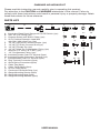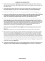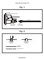
1
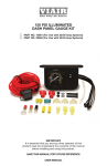
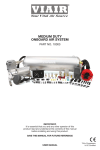
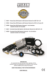
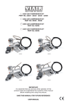
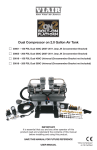
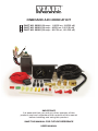
ONBOARD AIR HOOKUP KIT
PART NO. 20052 (30 amp - 110PSI on, 150PSI off)
PART NO. 20053 (30 amp - 85PSI on, 105 PSI off)
PART NO. 20055 (30 amp - 90 PSI on, 120 PSI off)
IMPORTANT:
It is essential that you and any other operator of this
product read and understand the contents of this manual
before installing and using this product.
SAVE THIS MANUAL FOR FUTURE REFERENCE
USER MANUAL
ONBOARD AIR HOOKUP KIT
Please read this instruction manual carefully prior to operating this product.
Pay attention to the CAUTION and WARNING statements in this manual. Failure to
comply with these instructions could result in personal injury or property damage. Retain
these instructions for future reference.
PARTS LIST:
A
B
C
D
E
F
G
H
I
J
K1
K2
L
M
N
O
P
Q
R
20
25
15
1
10
2
5
0
30
35
0
A. Illuminated Dash Panel Gauge with On/Off Switch (1pc)
B. 20Ft. Air Line Tubing (1pc)
C. Pressure Switch with Built-in Relay (1pc)
D. 20 Ft. Positive Extension Lead Wire
with 30A / 40A Inline Fuse (1pc)
E. 1/4” NPT (M) Quick Connect Coupler (1pc)
F. 1/4” NPT (F) Quick Connect Stud (1pc)
G. 1/4” NPT Female Tee (1pc)
H. 1/4” NPT Male Tee Compression Fitting (1pc)
I. Reducer (1/4” M to 1/8” F NPT) (1pc)
J. 1/4” Compression Fitting (1pc)
K1.Insulated Female Push-On Terminal (2pcs)
K2.Insulated Female Disconnect Terminal (1pc)
L. Insulated Male Push-On Terminal (2pcs)
M. Ring Terminal Connectors (3pcs)
N. Quick Splice Connectors (2pcs)
O. Cable Ties (6pcs)
P. Cable Tie Brackets (3pcs)
Q. Air Line Clips (3pcs)
R. Continuous Grommet Strip (1pc)
S1. Gauge Mounting Screws (2pcs)
S2. Gauge Mounting Nuts (2pcs)
S3. Gauge Mounting Washers (2pcs)
USER MANUAL
S1
S2
S3
INSTALLATION INSTRUCTIONS:
CHECK FOR CORRECT ONBOARD AIR HOOKUP KIT: Onboard Air Hookup Kits have been
designed for use with our 200, 300, and 400 series compressors. Please make sure that you have
the correct kit for use with your specific model compressor.
For Onboard Air Hookup to compressors or systems other than VIAIR components, refer to following
chart:
Compressor
Max. Amp Draw/Pressure Switch Cut-out Pressure
VIAIR
Onboard Air Hookup Kit
30 amp / 110PSI ON, 150 PSI OFF
Part No. 20052
30 amp / 85 PSI ON, 105 PSI OFF
Part No. 20053
30 amp / 90PSI ON, 120 PSI OFF
Part No. 20055
IMPORTANT:
The Illuminated Dash Panel Gauge has been fully function tested and calibrated for accuracy.
The air inlet on this gauge has a factory installed compression fitting. DO NOT attempt to
tighten or loosen the body of this compression fitting. Any adjustments will likely cause the
gauge to malfunction and void warranty. (See. Fig. 1)
NOTE: The Dash Panel Gauge included in this kit is rated for 150 PSI. Do not pressurize gauge over
150 PSI. Over-pressurization will cause the gauge to malfunction and will void your product warranty.
ONBOARD AIR HOOKUP KIT
STEP BY STEP INSTALLATION:
1.
Select a mounting location with a rigid mounting surface such as the bottom edge of the dashboard, on either side of the steering wheel column. Use the gauge mounting panel as a template; mark off 2 mounting points to be drilled. Drill two 13/64” diameter holes as marked. Do not mount Dash Panel Gauge at this time.
2.
Remove only the collar of the compression fitting from the back of the Dash Panel Gauge. Do not loosen or tighten the body of the compression fitting, which is permanently affixed to the air inlet of the gauge. Insert air line tubing through this collar, then, push air line tubing onto the barb of the compression fitting until the air line completely covers the barb. Tighten collar onto the body of the compression fitting. (See Fig. 1)
NOTE: When cutting air line tubing, always cut as squarely as possible. Use a hose cutter or razor blade. To ease insertion of air line tubing into fittings, lightly lubricate tip of air line, or soak air line tubing in warm water for about 5 minutes to soften the air line. When routing air line tubing, always remember to avoid sharp edges, heat sources and tight bends (Air line must be routed at least 12” away from exhaust systems & components.)
3.
Route the air line tubing on the Dash Panel Gauge to the air source. (See Figures 3 & 4) Do not cut air line at this time. In some cases a hole may be required to be drilled in the firewall to enable the air line to pass through the firewall to the air source. Make sure that the air line tubing is protected from any sharp edges of the drilled hole. A continuous grommet strip is included in your kit. Seat grommet strip around the edge of the hole, measure and cut strip to appropriate length. Work the strip around the hole opening until slot in the grommet strip seats firmly all the way around the edge of the hole. It will be necessary to seal any grommets or holes that have been cut or drilled so as to seal off elements from entering the cab area of vehicle. Use cable ties, air line clips, and or cable tie brackets to secure the air line to the vehicle.
IMPORTANT:
Drilling through firewall --- Always make sure what is on the other side of the
firewall before drilling. Make sure not to damage your vehicle’s electronic systems
or components when drilling.
4.
There are two tee fittings used in this kit, a female tee and a male tee. Install the quick connect coupler onto one leg of the female tee fitting as shown. (See Fig. 3) On the opposite leg, attach the male tee as shown to complete Tee Fittings Assembly. (See Fig. 3) Note: Apply sealant to threads prior to connecting all fittings.
5.
Select a rigid surface where the cable tie bracket can be mounted. Use provided cable tie(s) to secure the tee fittings assembly to the cable tie bracket. Use two cable ties if necessary to secure the tee fittings assembly. Keep in mind that the location of the tee
fittings assembly (female tee/male tee/quick connect coupler), should be close enough to the air compressor so that the 1.5 ft. leader hose of the compressor can reach the quick connect coupler.
USER MANUAL
ONBOARD AIR HOOKUP KIT
6.
Route air line to the male tee, measure and cut to appropriate length. Connect air line to one leg of the male tee as shown. (See Figs. 3 & 4) To connect air line to tee, remove collar of the male tee fitting, push airline onto the tee fitting until the air line completely covers the barb, and then tighten collar.
7. Attach the pressure switch with built-in relay to the remaining leg of the female tee by using the included reducer (1/4” M to 1/8” F) (See: Parts List Letter I). Wire the pressure switch with built in relay according to the instructions located on the pressure switch (See Fig. 3)
8. Place Dash Panel Gauge under dash over the two holes that were drilled. Using the provided screws, nuts and washers, mount the Dash Panel Gauge to the dash. (See Fig. 4)
9. Route 20 ft. extension lead wire from pressure switch to the dash panel gauge through the same hole drilled in the firewall for routing the air line. Measure and cut lead wire to appropriate length. Do not discard the remaining length of the wire, which has the Inline Fuse.
10. Attach one of the two female disconnect terminal to the wire that was routed from the pressure switch. There are two male spade connectors on the back of the On/Off switch.
Connect the female terminal connector to one of the male spade connector on the On/Off
switch. (See Fig. 4) Next, attach appropriate size ring terminal provided in the kit to the end of
the wire with the Inline Fuse. (The ring terminal will now be about 12” from the Inline Fuse.) This
wire is referred to as the power wire. Temporarily position the ring terminal at the power source
and route power wire to the dash panel gauge, measure and cut to appropriate length. (If additional wire is necessary, use appropriate gauge wire.) (See Fig. 4)
Attach the remaining female disconnect terminal to end of power wire, and connect to male
spade connector on the ON/OFF switch. (NOTE: Do not connect gauge to power source at
this time).
NOTE: When routing wire, use cable ties included in the kit to secure wire to the vehicle.
11. There are two wires, one red, and one black connected to the light bulb of the gauge. Connect
the red wire to a suitable fused dash panel circuit. Use the quick splice connector included in
the kit for wire connections. See Fig. 2 for how to use the quick splice connector. The black
wire is to be connected to a suitable ground source. Use the ring terminal or the quick splice connector for ground wire connection. (Note: Consult vehicle manufacturer’s electrical diagram.)
To use the quick splice connector, simply insert wire into one hole of the splice connector, and slip the connecting wire into the other hole. Once the wires are properly placed, close the top of
the quick splice connector using pliers if necessary. The connector will pierce the wire insulation to complete wire connection. (Note: If additional wire is required, use 22AWG to 18AWG wire for quick splice connector.) (See Fig. 2)
12. Connect the remaining length of air line to the remaining leg of the male tee. Route air line from
male tee to air tank, measure and then cut to appropriate length. Use the 1/4” compression fitting provided to connect air line to air tank. (See Fig. 3)
USER MANUAL
ONBOARD AIR HOOKUP KIT
13. Connect to air compressor is simple and easy with the Quick Connect Coupler by applying the 1/4” (NPT) Female Quick Connect Stud at the end of the compressor’s leader hose.
FYI: This quick connect setting is designed to have the option to air up tires directly from air compressor by connecting an air hose with Quick Connect Coupler to the applied Quick Connect Stud on compressor’s leader hose. (See Fig. 3)
NOTE: Compressor, fittings, & air hose connected to the compressor will become very hot during and immediately after use. Do not touch with bare hands. Use gloves if necessary.
14.
Before connecting the power wire to power source, check to make sure the On/Off switch
on dash panel gauge is in the OFF position. Connect the ring terminal of the power wire to
power source. (See Fig. 4) (This is the wire described in Step 11, which is connected to the ON/
OFF switch of the dash panel gauge.)
15.
Your Onboard Air Hookup Kit installation is now complete. Run the compressor to build up pressure in the air tank. Once air pressure reaches the preset cut out pressure, the compressor will shut off. Inspect all air line connections for leaks with soap and water solution. If a leak is
detected, the air line may not be cut squarely or pushed all the way in.
Fix connections as needed.
OPERATING INSTRUCTIONS:
1. Your Onboard Air Hookup Kit is designed for use in conjunction with an air tank. Make sure that your air tank is rated for at least 150 PSI maximum working pressure, and that your air tank setup is equipped with drain cock and pressure relief safety valve.
2.
Your Dash Panel Gauge comes with ON/OFF power switch. This convenient feature allows you
to shut off power to air compressor when air compressor operation is not required. When
constant supply of compressed air is required, simply turn the ON/OFF switch to the ON
position, and when pressure in your air tank reaches pre-set cut-out pressure, the pressure
switch will shut off your air compressor automatically. When pressure in your air tank drops below cut-in pressure, the pressure switch will automatically start air compressor.
3. Your Dash Panel Gauge is rated for maximum 150 PSI, do not use gauge on systems with
pressure ratings higher than 150 PSI.
USER MANUAL
TROUBLESHOOTING GUIDE:
PROBLEM
POSSIBLE CAUSE(S)
CORRECTIVE ACTION
Air Fittings Leak
1. Loose fitting connections
2. Air line tubing not published
all the way or cut squarely
1. Check connections with soap
& water solution. Reapply
sealant to fitting, reassemble.
Do not over-tighten.
(Make sure system pressure is
released before making repairs).
2. Remove air line, cut off one
inch, and reinstall.
Gauge leaks
1. Gauge connection loose
2. Air line not pushed all the way
in or cut squarely.
1. Remove air line from back of
gauge, cut off one inch, and reinstall.
2. Tighten compression fitting collar.
Compressor hooked up to 1. No power or ON/OFF switch is 1. Make sure power wire is
system will not run.
in the OFF position.
properly connected, and the ON/
2. Compressor hooked up to
OFF switch on Dash Panel
Gauge is in the ON position.
system will not run.
2. Check for the proper fuse
amperage. Replace fuse if needed.
Compressor hooked up to 1. Defective pressure switch.
system runs continuously. 2. If your air tank set up has a
safety valve, check for
defective safety valve.
1. Replace pressure switch.
2. Replace safety valve.
ONBOARD AIR HOOKUP KIT
Fig. 1
Dash Panel Gauge
Air Line
Compression
Fitting Body
Compression
Fitting Collar
Fig. 2
Quick Splice
Connector
(Open)
Quick Splice
Connector
(Closed)
Wire From
Lightbulb
Connecting Wire
USER MANUAL
ONBOARD AIR HOOKUP KIT
Fig. 3
Air Tank
Compression
Fitting
B
J
Air
Line
Drain Cock
F
E
H
G
Pressure
Switch
I
w/ built in relay
Compressor
(+) Lead
Compressor
Relay
Air
Line
C
white wire - to compressor
Thick
red wire
black wire
To Ground
Thin
red wire
To Fused
12-Volt
Car Battery
To Ground
B
Extension
Lead Wire
*Refer to the parts list to match the letters in the diagram to the correct corresponding parts.
Fig. 4
Fire Wall
Extension Lead Wire
Inline Fuse
Grommet
Female Terminal
Connectors
To Fused
Dash Panel Circuit
To Power
Source
On/Off
Switch
Quick Splice
Connector
To Ground
USER MANUAL
Air
Line
LIMITED WARRANTY:
VIAIR Corporation warrants this product, when properly installed and under normal conditions of
use, to be free from defects in workmanship and materials for a period of one year from its original
date of purchase. To receive warranty service or repair, please contact VIAIR Corporation.
Returns should be made within one year of the date of purchase, after a Return Goods Authorization
(RGA) number has been assigned by VIAIR Corporation. To obtain RGA, fax a copy of your receipt
to (949) 585-0188. For complete warranty details, please visit: www.viaircorp.com/warranty
PLEASE NOTE:
THIS WARRANTY COVERS PRODUCT DEFECTS ONLY; IT DOES NOT COVER INCIDENTAL
OR CONSEQUENTIAL DAMAGES AS RESULT OF MISUSE OR ABUSE.
15 EDELMAN • IRVINE, CA 92618
TEL: (949) 585-0011 • FAX: (949) 585-0188
www.viaircorp.com