Transcript
user manual
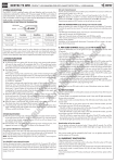
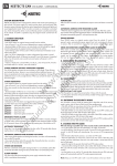
Note: Skoda Fabia is using 5wire actuators in the rear doors. Brown (color may vary)
wires routed from the wiring before connector are used as a door contact of the rear
door to connect with car alarm.
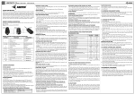
description of rc
Button
WARNING: Carefully read following instructions and technical specifications
in this manual before installation. The system must be installed and used only
according to this manual. The system is designed for vehicles with 12V power
supply. It has to be connected to 12V output and to the ground. Neither producer
or seller of the system is responsible for damages caused by incorrect installation,
using or operating of this product. Unprofessional operation or modification of
the system can damage the system alone, or the electric system of the vehicle
and leads to warranty loss. For proper working of the system we recommend the
installation to be made by authorized service.
I. System description - OEM LOCK key version
OEM LOCK is central locking system for SKODA vehicles.
Set OEM LOCK contains control unit, set of 4 actuators (two are designed to control
the front door and two to control the rear doors), cabling to connect the system, a
set of mechanical parts (rod, clamps, bolts and mounting rails). Actuators mounted
in the doors ensure movement of the rod (as in manual operation). Actuators in the
front doors contain a switch that senses the position of the lock and sends position
information to the controller. The control unit based on position changes in control
door lock controls all other door locks.
+12V
GND (-)
blue
green
black
blue
green
white
brown
blue
green
black
blue
green
white
brown
BR
ignition turned off
a: turn on function „LOCK CHECK“
b: turn off function „LOCK CHECK“
function „LOCK CHECK“ is disabled
function „LOCK CHECK“ is enabled
„LOCK CHECK“ function activation (last pressed
button on RC)
always (only RC KEY)
„LOCK CHECK“ function activation (last pressed
button on RC)
always (only RC MAX)
lights up the LED diode in the front on RC
always (RC MAX, RC LINE)
Note: Lock Check function is available only at RC MAX and RC KEY!
Button on RC KEY with symbol = button on the others RCs with symbol
FR
II. system description - oem lock version with RC
OEM LOCK is central locking system with remote control. It is suitable for Skoda
vehicles. System is controlled with RC (possibility to remote control of trunk opening)
or with original key. Communication between control unit and RC is protected by
floating code. OEM LOCK set contains of two control units, which provides propert
function of system, set of 4 actuators (two are designed to control the front door and
two to control the rear doors), cabling to connect the system, a set of mechanical
parts (rod, clamps, bolts and mounting rails). Actuators mounted in the doors ensure
movement of the rod (as in manual operation). Actuators in the front doors contain
a switch that senses the position of the lock and sends position information to the
controller. The control unit based on position changes in control door lock controls all
other door locks (key control).
connector CN1 (4-pin) - control unit 1
Brown (-) System unlock (output wire)
White (-) System lock (output wire)
Red (+) Power supply +12V (input wire)
Black (-) GND of vehicle (input wire)
connector CN2 (2-pin) - control unit 1
Orange (+) Directional lights (output wire)
Fialový (-) Trunk opening (output wire)
connector CN3 (12-pin) - control unit 2
Brown (-) System unlock (input wire)
White (-) System lock (input wire)
Red (+) Power supply +12V (input wire)
Black (-) GND of vehicle (input wire)
Green - wire for actuator connection
Blue - wire for actuator connection
Brown - wire for actuator connection
White - wire for actuator connection
Black - wire for actuator connection
CN2
CN1
Control unit 2
CN3
15A
.
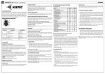
“lock check” function - RC MAX
This function allows you to check which button was pushed last time. Buttons for
locking and unlocking can be checked and therefore user can check, whether
he locked the car or not. LOCK CHECK function is optional and turned off from
factory. You can activate the function by holding buttons and together for two
seconds. When activating, icons for locking and unlocking will blink once. When
deactivating, they will blink twice. If the function is activated, you can check the
last pushed button by briefly pushing button . After that the icon of locking or
unlocking will light for aprox. 0,8 sec, depending on which button was pushed
last time.
Warning: When the LOCK CHECK function is activated, battery life will be
shorter
Low battery indicator on the remote
If the battery indicator will flash in blue colour when locking or unlocking vehicle,
the battery in remote control is weak and you have to replace it with new one.
Torch function on RC MAX, RC LINE
By holding button for more than 1 sec, high power LED in front of the remote will
light. LED will light as long as you hold the button or for a specified time, even if
you hold the button longer (only RC MAX). The time how long the LED can glow is
adjustable (only RC MAX).
LED light duration setting on rc max
duration of LED light can be adjusted from 1 to 30 sec or without limit. Push buttons
and
together for 1 sec. Red LED will flash for 3 sec. After those 3 sec, the LED
wil start to flash in 1 sec intervals. Press the button for as long as you wish the
light to be switched on (max. 30 sec). If you don’t press any button, light duration
will be unlimited. Programming will automatically end after 30 sec.
Funkcia “lock check” pri RC KEY
- press buttons and . Turn on/turn off of “LOCK CHECK” function (last pressed button
on RC control). Turning on of this function is signalized by green flash of LED diode on
RC. Turning off by red flash of LED diode. This function is turned off by factory settings.
- press button twice until 1 second and “LOCK CHECK” funcion will be activated (last pressed button on RC control). Every press of button is signalized by red
flash of LED diode, then LED diode flashes with green for 1x or 2x, depending on
which button was pressed last - (1x green flash) or button
(2x green flash).
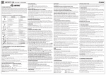
schematic - oEM Lock version with RC
BL
FL
for more
than 1 sec.
trunk open
Control unit 1
red
black
trunk opening
(-500mA output)
+12V
GND (-)
programming trunk opening output
directional lights (+ output)
directional lights (+ output)
BR
BL
FL
black
blue
green
white
brown
red
black
brown
lock input (-)
white
unlock input (-)
until
1sec.
locked vehicle
FR
Installation and maintenance
installation of control units
Control units must be installed into interior of vehicle. The most suitable place for
installation is under the dashboard.
When installing the servo, remove the upholstery from the door, to which they will
be mounted. Install the servomotors according to manuals for specific type of vehicles. Once installed and connected to the rod or to the lock, test functionality with
hand movements, if the operation is smooth and mechanism isn`t get stuck. If everything is allright, connect actuators wires to the power wires from unit according
to schematic. If the locks on some doors require a reverse operation, exchange of
power supply wires between them is required (blue and green wire). If this actuator
is control actuator, switch white and brown between them, too. When installing
wires pay attention to moving windows or doors to prevent wires from damage.
The location of the inlet wires pay attention to when moving a window or door damage. After connecting all the servo motors, wires and checking the correctness of
engagement, you can test the functionality of the system. In the event that control of
key locking system is active in one direction only, or not responding at all, move the
rod so that the moving part of the servo motor moves in the middle range of motion
Warning: If lock freezes in winter, even actuator can not unlock the door. Therefore, it must first be lock defrosted (with defrost liqiuds or by placing the vehicle into
heated room), then to try to unlock the doors using the central locking. Before the
winter season, pay attention to lubricate locks.
programming the remote controls
(1x for RC1, 2x for RC2 ...)
- programming will be automatically ended after 5 seconds after programing the last
RC
Adding or deleting programmed remote controls when programming
new ones
- disconnect power supply and press valet switch
- when pressing the valet switch, connect/disconnect power supply 7 times within
10 seconds, while for the seventh time power remains connected. Release the valet
switch
- LED diode on control unit starts flashes quickly to confirm entry into the programming
mode
- if you want to delete old RCs when adding new ones, press on programmed RC lock
button (factory set). Flashing LED will turn on permanently for 2 seconds, then starts
flashing again.
- if you want to keep old RCs when adding new ones, press on programmed RC unlock
button. Flashing LED will turn on permanently for 5 seconds, then starts flashing again.
- programming will be automatically ended after 10 seconds
blue
green
15A
2x
for 2sec.
vehicle unlock
black
blue
green
white
brown
connector CN1 (12-pin) - inputs/outputs connector
Brown (-) System unlock (input wire)
White (-) System lock (input wire)
Red (+) Power supply +12V (input wire)
Black (-) GND of vehicle (input wire)
Green - wire for actuator connection
Blue - wire for actuator connection
Brown - wire for actuator connection
White - wire for actuator connection
Black - wire for actuator connection
Note: Skoda Fabia is using 5wire actuators in the rear doors. Brown (color may vary)
wires routed from the wiring before connector are used as a door contact of the rear door
to connect with car alarm.
+
condition
ignition turned off
blue
green
Schematic - OEM LOCK key version
for 1sec.
function
vehicle lock
purple
CENTRal locking system
orange
keetec OEM LOCK
10A
EN
Up to 10 remote controls can be programmed into system.
- disconnect device from power supply and press valet switch
- when pressing the valet switch, connect/disconnect power supply 5 times within 7
seconds, while for the fifth time power remains connected. Release the valet switch
- LED diode on control unit starts flashes quickly to confirm entry
into the programming mode and the directional lights will flash 5 times.
- press any of the button on RC within 5 seconds
- successful programing of RC is confirmed by flash of directional lights
Output to open the luggage compartment is factory set to that after its activation has
been switched on for 1 second. The system allows the output can be set in three ways:
1. activate the output for the set time (1 to 300 sec.). Once activated, the output to
open the trunk is switched on for set time.
2. permanent turn on the output when pressing the trunk open button and by next
press output will be closed
3. in idle mode the output is „-“ 12V. Once activated, the output of the boot
opening is with no tension on it and the output for directional lights is permanently
switched on. Another pressing the button to activate the output to open the boot,
turn off output of directional lights and on output for trunk again appears „-“ 12V
Programming process of each option:
- disconnect power supply and press valet switch
- when pressing the valet switch, connect/disconnect power supply 3 times within 5
seconds, while for the third time power remains connected. Release the valet switch
- LED diode turns off for a while and then turns on to confirm entry into the programming
mode (procedure is the same for all options, proceed as follows according to each
option)
- programming function 1: press trunk opening button once. LED diode starts flashes in
1 second intervals óda začne blikať v sekundových intervaloch (LED flashes number
determines how long the trunk output will be switched on after activation). When the
number of flashes corresponds to time how long you want to output be switched on,
press again the trunk open button. The length of the output is now set.
- programming function 2: press and hold trunk opening button. LED diode switched
off. When LED diode flashes once, release the button. Output is now set.
- programming function 3: press and hold trunk opening button. LED diode starts
flashing in intervals (one flash, two flash). After two flashes release the button. Output
is set now.
System RESEt
- disconnect power supply and press valet switch
- when pressing the valet switch, connect/disconnect power supply 10 times within 13
seconds, while for the tenth time power remains connected. Release the valet switch
- directional lights flashes three times. system is now reseted to the factory settings, also
all programmed RCs are deleted from system
Note: The device OEM LOCK (version for remote control) is
working in the band 433.2 MHz. Ask your dealer for Declaration of conformity for
this product.
Technical parameters
Power supply
Working temperature
Stand-by current
Working frequency (P LOCK)
Lift of actuator
12V +/- 25%
from -30°C to 70°C
max. 10mA
433,92 MHz
18 mm