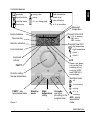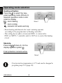
1
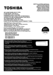
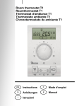
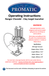
ENG Room unit DEU Raumeinheit ITA Termostato ambiente FRE Thermostat d‘ambiance DD2+ + ENG Termostato ambiente DD2+ ITA Thermostat d’ambiance DD2+ FRE Raumeinheit DD2+ DEU Room unit DD2+ User manual Preface .................................................................................................... 8 Operating mode selection ....................................................................... 10 Selection between heating or cooling ...................................................... 11 Setting the day and night temperature .................................................... 11 PARTY and ECO operating mode ........................................................... 12 Setting the accurate time ......................................................................... 13 Remote control ........................................................................................ 14 Room unit locking .................................................................................... 14 One time manual d. h. w. warming activation.......................................... 14 Indication of the controlled devices on display ......................................... 14 Command to quick save and quit (Escape) ............................................. 15 Battery replacement ................................................................................ 15 Display of auxiliary temperature sensor. ..................................................... 15 Setting manual Menu ....................................................................................................... 16 Factory settings - DD2+ reset.................................................................. 21 Solid fuel boiler systems .......................................................................... 21 Disable of room sensor on DD2+ ............................................................ 22 Installation manual Place of mount ........................................................................................ 22 Wall plate mount ...................................................................................... 22 Wiring connections .................................................................................. 24 Room unit synchronisation ...................................................................... 25 Connecting the Telewarm ....................................................................... 26 Connecting the auxiliary temperature sensor .......................................... 26 Coding switch .......................................................................................... 27 DD2+ malfunctions .................................................................................. 28 Technical data ......................................................................................... 30 Conformity with standards and directives ................................................ 30 Disposal of Old Electrical & Electronic Equipment ................................. 31 Connecting the DD2+ to heating controller .......................................... 113 7 ENG Table of contents ENG Preface DD2+ is a modern designed and efficient device for comfort heating control. It has the following features: - operating mode selection - requested room temperature setting LEGEND Hold key while pressing other keys. Hold key until you hear a beep sound. Press and release key. Press key to increase or decrease value. USER MANUAL 8 - mixing valve - pump - heat accumulator - liquid fuel boiler - solid fuel boiler - d. h. w. storage tank - solar collectors - gas boiler ENG Controlled devices - direct circuit - d. h. w. circulation - heat pump Measured temperature Empty batteries Program timer CH2 - d. h. w. warming Time and day ON - active OFF - inactive Remote activation Program timer CH1 Frost protection 1 2 Keyboard locking - day temperature - night temperature - circuit 1 - circuit 2 ECO PARTY + Knob for setting the day temperature Room unit does not control the heating circuit (only by WDC and CMP25-2 controllers). Operation mode - off - room heating PARTY - day temperature mode Stand by mode Night temperature setting Picture 1 9 On mode operation according to the program timer - cooling - d. h. w. warming ECO - saving temperature mode USER MANUAL ENG Operating mode selection Heating activation Press key to select the requested operating mode (Picture 2). Selected operation mode is indicated on display. - room heating - room cooling - domestic hot water warming Picture 2 - Room heating and domestic hot water warming operates according to the program timer of heating controller. - This setting has no affect, if room unit DD2+ is connected to WDC or CMP25-2 controller and it is NOT set to control the heating circuit. Stand-by Press key (Picture 3). On the display appears symbol . Frost protection remains active. Picture 3 i USER MANUAL Frost protection temperature is 6 °C and can be changed in program group P1.3 (page 18). 10 To switchover between heating and cooling and in reverse, hold key for approximately 15 seconds (Picture 4a). Release key after you hear a beep. The display writes out active mode for a few seconds, HEA- heating or cOO- cooling (picture 4b). Picture 4a Picture 4b Setting the day and night temperature Day temperature Turn knob to set the requested day temperature between 10 °C and 30 °C (Picture 5). Picture 5 Night temperature Hold key ( ) for approx. 5 seconds (Picture 6a). Release key after you hear a beep. Now press key or to set the requested night temperature (Picture 6b). To save and quit setup, press key ( ) once again. Picture 6a Picture 6b 11 USER MANUAL ENG Selection between heating or cooling ENG PARTY and ECO operating mode PARTY - day temperature operation Press key .. Use key or to set duration of the PARTY mode between 1 and 24 hours. For permanent PARTY mode, select on. To stop PARTY mode at anytime, press key i . The PARTY temperature increase above the day temperature is setted in parameter P1.9 (page 18). ECO - night temperature operation Press key . Use key or to set duration of the ECO mode between 1 and 24 hours. For permanent ECO mode, select on. To stop ECO mode at anytime, press key i . The ECO temperature reduction from the required day temperature is setted in parameter P1.2 (page 18). USER MANUAL 12 Hours Hold key and press key to set the hours (Picture 7). ENG Setting the accurate time* or Picture 7 Minutes Hold key and press key to set the minutes (Picture 8). or Picture 8 Day Hold both keys and , then press key or to set the day (Picture 9). The days are marked from 1 to 7. Monday is marked as 1 and Sunday as 7. Picture 9 i If the DD2+, by battery exchange, isn’t functional for a while, the time is set to Monday, 20:00. * When connected to PROMATIC WDC and CMP25-2 the time is automatically synchronized with the controller. 13 USER MANUAL ENG Remote control With telephone is possible to remotely activate the day temperature operating mode. For analogue telephone line device G1-D is available. Room unit locking Hold key for 15 seconds. Release the key after you hear a beep. Symbol indicates locked room unit. To unlock the DD2+, again hold key for 15 seconds. Setting or modifying the parameters by locked DD2+ isn’t possible or is limited. i DD2+ locking is set in service group S1.4 (page 20). One time manual d. h. w. warming activation Hold key i for 5 seconds. Release the key after you hear a beep. One time manual domestic hot warming is automatically deactivated, when requested d. h. w. temperature is reached or at the latest after 1 hour. Indication of the controlled devices on display If the indication of controlled devices is deactivated (setting in program group P1.8), the currently controlled devices can be viewed by holding the key and pressing the key (Escape). All the controlled devices will appear on the display for 15 seconds. USER MANUAL 14 Every time you wish to quick save and quit setup, hold key press key . Release both keys after you hear a beep. i and All modifications made, are stored. This command has no affect in program and service settings. Battery replacement Empty batteries are indicated with the symbol on display. We suggest the battery replacement every 2 years. DD2+ is supplied with two alkaline batteries 1.5 V type AAA. Battery socket is inside the DD2+. To remove room unit from the wall plate, do the following. Hold room unit in height of keys and pull it towards yourself (Picture 10 - OPEN). After battery exchange, put DD2+ back on the wall plate, by doing the following. Hook DD2+ on top and push it with bottom towards the wall plate (Picture 10 CLOSE). OPEN CLOSE Picture 10 Battery exchange should be done within 20 seconds. In other case you will have to set the accurate time again. Display of the auxiliary sensor temperature In normal display mode, hold key i and press key (Escape). If the auxiliary sensor isn’t connected, this command isn’t active. 15 USER MANUAL ENG Command to quick save and quit (Escape) ENG Menu All data and parameters are joined into 4 groups: d1 ·············· room unit data P1 ·············· basic parameters S1 ·············· service parameters S3 ·············· service parameters Menu To enter menu hold key and press key (Picture 11). Release keys after you hear a beep. The display writes out first group d1. Picture 11 Menu navigation In menu have keys new meaning, marked bellow them (Picture 12). To move between the groups press key to move to the left and key to move to the right (Picture 12). To move within the group press key to move down between the lines and key to move up between the lines. For your better understanding are all the lines marked. First two symbols mark the group and the third symbol successive number of the line in group (Picture 13). Move to the right Move to the left Picture 12 SETTING MANUAL Move down or decrease 16 Move up or increase ENG Entrance Parameters S are by default (factory) settings locked. Picture 13 i Which data and settings are hidden is set in parameter S3.1. Successive Nr. of the line Picture 14 Parameter Group name Room unit data d1 This group is sort of DD2+ ID. In this group are information about DD2+. The information are displayed in the following order: - [d1.1] room unit type (DD2+) - [d1.2] software version - [d1.3] heating or cooling - [d1.4] built-in temperature sensor calibration - [d1.5] battery voltage 17 SETTING MANUAL ENG Basic parameters P1 Basic parameters P1 are used for the thermostat user settings. To change the selected parameter, hold key for approximately 5 seconds. Parameter starts to flash. Press key or to set the parameter value. To store the setted value, again hold key for approximately 5 seconds. Group P1 contains the following parameters; (factory setting): - [P1.1] night temperature (6 °C ÷ 26 °C); (17 °C) - [P1.2] temperature reduction in ECO mode (0 °C ÷ -9 °C); (-3 °C) - [P1.3] frost protection temperature (0 °C ÷ 20 °C); (6 °C) - [P1.4] temperature sensor calibration (-2 °C ÷ 2 °C); (0 °C) - [P1.5] auxiliary temperature sensor calibration (-2 °C ÷ 2 °C); (0 °C) - [P1.6] display of measured temperatures (1 - room, 2 - outdoor, 3 - room and outdoor alternating, 4 - requested temp.); (1) - [P1.7] beeper mode (- - - silent, 1 - by typing, 2 - by timer switchover, 3 - by typing and timer switchover); (1) - [P1.8] display of controlled devices (1 - visible, 2 - hidden); (1) - [P1.9] temperature increase in PARTY mode (0 °C ÷ -9 °C); (0 °C) - [P1.10] temperature display by ESC command in normal display (see table): Parameter value --- WDC CMP25-2 D10, D20 / CMP25 Auxilliary sensor DD2+ Auxilliary sensor DD2+ Auxilliary sensor DD2+ 1 T1 Room temperature Outdoor temperature AF 2 T2 Not used. Room temperature RF 3 T3 Outdoor temperature Stand-pipe VF 4 T4 Stand-pipe Return-pipe RLF SETTING MANUAL 18 WDC CMP25-2 D10, D20 / CMP25 5 T5 Return-pipe Boiler KF 6 T6 Not used. Return into boiler RLKF 7 T7 Boiler Domestic hot water BF1 Domestic hot water BF2 or solid fuel boiler KF2 8 T8 Not used. 9 / Not used. Solar collectors KTF 10 / Not used. Auxilliary room sensor RF2 11 / Not used. Floor EF 12 / Not used. Solid fuel boiler KF2 13 / Not used. Sensor on clamp C.12 14 / Sensor on clamp T1 Sensor on clamp C.17 19 SETTING MANUAL ENG Parameter value ENG Service parameters S1 Service parameters S1 are intended for DD2+ service settings. To change the selected parameter, hold key for approximately 5 seconds. Parameter starts to flash. Press key or to set the parameter value. To store the setted value, again hold key for approximately 5 seconds. In service parameters S1 are the following settings; (factory settings): - [S1.1] measured temperatures roundup (0.1 °C, 0.2 °C, 0.5 °C, 1.0 °C); (0.5 °C) - [S1.2] room temperature (- - - no sensor, 1 - built in sensor, 2 - auxiliary sensor, 3 - avg. of built in and auxiliary sensor); (1) - [S1.3] menu auto-exit (1 - 20 s, 2 - 200 s); (1) - [S1.4] room unit locking (- - - no locking, 1 - no locking, but limited function of key , 2 - enabled key Party and knob, 3 - enabled only key Party, 4 - full lock, 5 - room temperature sensor influence is disabled for at least 5 hours); (2) - [S1.5] max. scale for day temperature setting (10 °C ÷ 40 °C); (30 °C) - [S1.6] min. scale for day temperature setting (0 °C ÷ 40 °C); (10 °C) Service parameters S3 Service parameters S3 are intended for DD2+ service settings. To change the selected parameter, hold key for approximately 5 seconds. Parameter starts to flash. Press key or to set the parameter value. To store the setted value, again hold key for approximately 5 seconds. In service parameters S3 are the following settings; (factory settings): - [S3.1] Parameter locking (- - - no locking, 1 - locked are groups S, 2 - locked are parameters S and P, 3 - locked complete menu); (1) SETTING MANUAL 20 Access to parameter S3.1 is possible in the following way. Hold key for 20 seconds (picture 15). Release the key after you hear a beep. On the display appears parameter (S3.1). Now it’s possible to modify this or any other parameter. Picture 15 Factory settings - DD2+ reset To restore the factory settings hold keys and for approx. 20 seconds (Picture 16). Release keys after you hear a beep. Picture 16 Solid fuel boiler systems If the solid fuel has burned down, DD2+ signalizes it with symbol on display and periodic beep sounds every 20 seconds. Signalisation of burned down solid fuel is active only in day temperature mode heating period. i Applies only to schemes from 408 to 413. 21 SETTING MANUAL ENG i ENG Disable of room sensor on DD2+ Room unit has built in function to disable room sensor influence for 5 hours. To activate this function, hold key ECO for 15 seconds (Parameter S1.4 needs to be set to value 5!). This function is especially useful in cases of heating with fireplace or other heat source, which is operating independently to controlled heating system. Place of mount Place of mount is very important for proper DD2+ operation. Suitable places are inner walls, which aren’t sun lighted or exposed to sources of heat and wind. DD2+ should be mounted approximately 150 cm above the floor (Picture 17). Picture 17 SETTING MANUAL 22 ENG Wall plate mount Remove the DD2+ from the wall plate, by doing the following. With one hand hold DD2+ in height of keys and with other hand the wall plate and pull them apart (Picture 18). Picture 18 Room unit DD2+ is intended for wall mounting. In case you don’t have installed a flush box, use the drilling template and mark drilling holes. Use enclosed screws to fasten the wall plate on the wall (Picture 19). After you have done connecting the wires (see chapters Wiring connections and Connecting the DD2+ to heating controller), put DD2+ back onto the base by doing the following. Hook DD2+ on top of the wall plate and push it with bottom towards the wall plate (Picture 10 - CLOSE). flush box wall Picture 19 23 SETTING MANUAL ENG Wiring connections WARNING: Mounting and wiring connections must be done by a qualified installer or authorized company. Local regulations or VDE 0100 and EN IEC 60364 regulations for electrical installations must be considered by doing the wiring connections. Bring the wires through the opening in bottom of the wall plate (Picture 19 - position A). Connect the terminals 1 and 2 on room unit with terminals GND and COM on controller (Schemes on pages113-116). After you have connected the wires, put DD2+ back on the wall plate. On the display appears rectangular frame (Picture 27). If the rectangular frame doesn't appear on the display, the communication between room unit and controller isn't established. For troubleshooting refer to the DD2+ malfunctions, page 28). Picture 20 INSTALLATION MANUAL 24 After the wiring connection, DD2+ needs to be synchronised with the controller. To synchronise the DD2+, hold key for 30 seconds. After you hear two successive beeps, release the key. The DD2+ synchronisation is now in progress. When you hear another beep, the DD2+ is synchronised and you can continue with your work. DD2+ needs to be synchronised with the controller after all the temperature sensors are connected.* The signal cable between DD2+ and controller must not exceed 50 meters. * Synchronisation is not required by WDC and CMP25-2 controllers. 25 INSTALLATION MANUAL ENG Room unit synchronisation* ENG Connecting the Telewarm Connect Telewarm G1-D into the terminals 3 and 4 on the DD2+ wall plate (Picture 21). To learn more about connecting the Telewarm on electric and telephone network see User manual for Telewarm. Connecting the auxiliary temperature sensor Always connect the auxiliary temperature sensor into the connector terminals 3 and 4 on wall DD2+ plate (Picture 21). Set the parameters for this sensor in service group S1. Telewarm for remote activation, can also be connected in the same terminals. Picture 21 On the DD2+ can be connected only MURATA type sensors. This sensors are: - outdoor sensor AF/M, - room sensor PS10/M, - immersion sensor TF/M. INSTALLATION MANUAL 26 On the DD2+ backside is the 4-pole coding switch. The meaning of switches is: Room unit DD2+ is connected on WDC10B, WDC10, WDC20, CMP25-2. Room unit DD2+ is connected on Promatic D10, D20, CMP25 or older devices. S1=OFF S1=ON S2=OFF Room unit controls circuit #1 Room unit controls direct circuit S2=ON Room unit does not control circuit #1 Room unit does not control direct circuit S3=OFF Room unit controls circuit #2 Room unit controls mixing circuit S3=ON Room unit does not control circuit #2 Room unit does not control mixing circuit S4=OFF Room unit #1 Room unit S4=ON Room unit #2 Service console i Coding switch factory setting is OFF. 27 INSTALLATION MANUAL ENG Coding switch ENG DD2+ malfunctions Room unit automatically detects eventual malfunctions and signalises them on the display. These errors are: Er1, Er2, Er3 and Er4. - temperature sensor malfunction If the display writes out (Picture 22), it means built-in temperature sensor is in malfunction. Send room unit to the nearest authorised service or dealer. Picture 22 - malfunction of one or more sensors, connected to the controller If the display writes out (Picture 23), it means one or more temperature sensors, connected to the heating controller is in malfunction. Check the resistance and connection of the sensors, to eliminate the malfunction. i DD2+ signalises error also when DD2+ isn’t synchronised with the controller (refer to the chapter Room unit synchronisation, on page 25).* * Synchronisation is not required by WDC and CMP25-2 controllers. INSTALLATION MANUAL 28 ENG Picture 23 - malfunction in communication link with the controller If the display writes out (Picture 24), communication link between room unit and controller isn’t established or the link isn’t established properly. Possible causes are: - connection between room unit and controller is disconnected. On the display does not appear the rectangular frame (Picture 25). Check the connection between room unit and controller. Picture 24 Picture 25 - malfunction of the auxiliary temperature sensor, connected to the room unit When the display writes out (Picture 26), auxiliary (external) temperature sensor is in malfunction or isn’t connected. Check the connection and resistance of the sensor. Picture 26 29 INSTALLATION MANUAL ENG Technical data Model: ............................................. DD2+ Power supply: ................................. 8 V d.c.; max 20 V d.c and 2 batteries LR03, type AAA Temperature sensor: ...................... Murata NTC (10 kE) Safety class: ................................... IP 30 by EN 60529 Degree of protection: ...................... II by EN 60730-1 Housing: ......................................... ABS thermoplastic, white Dimensions (l × w × h): ................... 72 × 32 × 112 [mm] Weight: ........................................... 150 g Conformity with standards and directives Room unit DD2+ corresponds to following guidelines and standards: · LVD: Low voltage directive 2006/95/EC, · EMC: Directive for Electromagnetic compatibility 2004/108/EC, · RoHS: Directive for hazardous substances in electric and electronic appliances 2002/95/EC. Product description: Room unit Model name: DD2+ Applied standards: EN 60730-1. INSTALLATION MANUAL 30 Disposal of Old Electrical & Electronic Equipment (Applicable in the European Union and other European countries with separate collection systems). This symbol on the product or on its packaging indicates that this product shall not be treated as household waste. Instead it shall be handed over to the applicable collection point for the recycling of electrical and electronic equipment. By ensuring this product is disposed of correctly, you will help prevent potential negative consequences for the environment and human health, which could otherwise be caused by inappropriate waste handling of this product. The recycling of materials will help to conserve natural resources. For more detailed information about recycling of this product, please contact your local city office, your household waste disposal service or the shop where you purchased the product. 31 STATEMENTS ENG Disposal of Old Electrical & Electronic Equipment