1
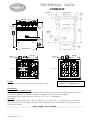
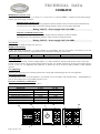
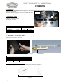
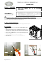
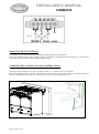
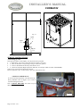
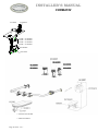
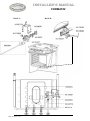
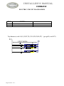
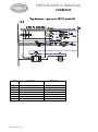
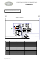
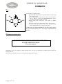
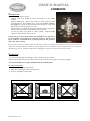
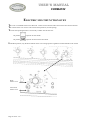
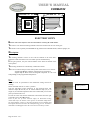
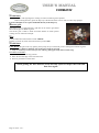
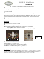
Fourneau «Cormatin» WARNING: If the information in this manual is not followed exactly, a fire or explosion may result causing property damage, personal injury or death. - Do not store or use gasoline or other flammable vapors and liquids in the vicinity of this or any other appliance. - WHAT TO DO IF YOU SMELL GAS. Do not try to light any appliance. Do not touch any electrical switch. Do not use any phone in your building. Immediately call your gas supplier from a neighbor’s phone. Follow the gas supplier’s instructions. If you cannot reach your gas supplier, call the fire department. - Installation and service must be performed by a qualified installer, service agency or the gas supplier. WARNING: THIS RANGE CAN TIP INJURY TO PERSONS COULD RESULT INSTALL ANTI-TIP DEVICE PACKED WITH RANGE SEE INSTALLATION INSTRUCTIONS Page 1 of 40 – US – Page 2 of 40 – US – TECHNICAL DATA CORMATIN 700 mm - 27 9/16 ’’ 768 mm* 30 1/4 914 mm* 36’’ 399 mm* 15 11/16 ’’ 478 mm-18 13/16 ’’ 55 mm 2 3/16 ’’ 350 mm 13 3/4 ’’ Fig. 2 55 mm 2 3/16 ’’ 350 mm 13 3/4 ’’ Fig. 3 Layout: 3- or 4-burner cook’s stove (Figure 1), G.N 1/1 oven (Figures 1, 2 & 3). * The range Height is adjustable: 910 mm-35 13/16 ’’ to 926 mm-36 7/16 ’’ Description: Cooking surface and body panels: Enamelled steel or stainless body panels AISI 430. Pressing cooking surface (stainless steel AISI 304) (Figures 2 and 3). 3or 4- burners of different size and power individually controlled by a safety valve. Electrical ignition. TRADITION” model equipped with a 385 x 510 mm (15 5/32’’ x 20 5/64’’) heating plate. Gas oven: Enamelled sheet metal. Dimensions L x D x H: 535 mm (211/16’’) x 465 mm (1819/64’’) x 300 mm (1151/64’’). 3 shelf level with 70 mm spacing, 69 liters / 2.44 ft3. Heating provided by thermostatically controlled burner, thermocouple safety cutouts. Electrical ignition. Power supply: 120 VAC 60Hz. Page 3 of 40 – US – TECHNICAL DATA CORMATIN Multifunction electric oven: Dimensions L x D x H: 535 (211/16’’) x 420 (1617/52’’) x 265 (1027/64’’); 68 litres/ 2.40 ft3, 3 shelf level with 70 mm spacing Electric grill with a rating of 2850 W Function static electric oven: One 1700 W element at the base and a peripheral 1200 W element in the roof which operate simultaneously. Thermostatically controlled roof and base heating elements, safety cut-out by safety thermostat. Rating: 2900 W – Power supply: 240 Volts 60Hz. Function ventilated electric oven: Heating provided by one circular 2650 W element and one peripheral of 1200 W element.. Thermostatically controlled heating elements, safety cut-out by safety thermostat. Rating: 2650 W – Power supply: 240 Volts 60Hz. Accessories: One drip tray, one shelf, one pastry tray per oven. Shipment-Packaging: Unpack and check the appliance is in good condition. In case damage, note any reservations on the delivery note and confirm them within 48 hours by registered letter with confirmation of delivery to the carrier. Appliance LG 731 G Width Depth 850 mm / 33.4’’ 840 mm / 33.1’’ Height mm 1070 mm / 42.1’’ Weight Gross/Net 105 kg / 89 kg – 233 / 197 lb Gas connection: 1/2” ID NPT (Sch 40) inlet, on male coupling (Figures 1, 2 and 3). Sealant on all pipe joints must be resistive to LP gas. If used, a flex gas line for the gas supply must be metal of at least 1/2” ID NPT approved by an approved certifying agency (A.G.A., C.G.A,. etc.) in compliance with ANSI Z21.41 and Z21.69. Never use a hose made of rubber or other synthetic material. Gas supplying: Appliance gas supplying can be switched, please refer to rating plate and marking at the rear of the appliance. Electrical connection: On terminal block at the rear of the appliance. Use flexible cord in accordance with standard N.E.C., AINSI/NEMA 701996 or latest edition (not cord provided) (Figures 1 & 3). Pressures and hourly consumption: Appliance gas supplying can be switched (table 1). Table 1 6’’ WC Natural Gas Btu / hr 13500 18000 15000 11000 5000 PRESSURE GAS Burner Oven Ultra fast (UF) Tradition (T) Intensive (I) Fast (F) Semi fast (SF) SF UF F Page 4 of 40 – US – T 10’’ WC G.P.L. Btu / hr 11000 17000 13000 10000 5000 SF F F SF F I Fourneau «Cormatin» INSTALLER'S MANUAL Appliances must be installed in a workmanlike manner in accordance with the instructions in this manual and locally applicable regulations. This manual will be handed over to the user after installation. Page 5 of 40 – US – Page 6 of 40 – US – INSTALLER’S MANUAL CORMATIN Cabinet preparation: Fig. 4 A B mm 762-914 330 ’’ 30-36 13 C D 457 18 914 36 E F G H I 290 420 235 405 20 117/16 16 9/16 9 1/4 15 15/16 13/16 J K L M 60 765 865 705 2 3/8 30 1/8 34 1/16 27 3/4 N O 51 2 671 26 The range is a free standing unit. If the unit is to be placed next to cabinets, the clearances shown in Figure 4 are required. The range cooktop surface must be no lower than the adjacent base cabinet countertop surface. Min clearances to combustibles : 0 ’’ (0 mm) from rear (with spacer installed). 0 ’’ (0 mm) from sides below 36’’ (914 mm) height. 2’’ (51 mm) from sides above 36’’ (914 mm) height. Cabinets 13’’ (330 mm) deep may be installed above the range at least 30’’ above the plane of the cooking surface. Use range only with factory supplied legs. Page 7 of 40 – US – INSTALLER’S MANUAL CORMATIN IMPORTANT Recommended to be installed under an exhaust hood. In the commonwealth of Massachusetts, the appliance must be installed by a licensed plumber or gas fitter. Do not install this unit near combustible walls, partitions, pieces of furniture or decorative material unless these are covered by adequate material of the non-combustible type. Making sure the resulting installation meets fire regulations. IMPORTANT THE APPLIANCE MUST BE INSTALLED IN ACCORDANCE WITH THE LOCAL CODES OR National Fuel Gas Code, ANSI Z223.1 or latest edition. IMPORTANT Manual shut-off valve should be installed in an accessible location in the gas piping external to the appliance for the purpose of turning on or shutting off gas to the appliance. A location at the back of an adjacent cabinet is recommended. Before connection: Check: - Pipework is perfectly clean in order to prevent the injectors becoming blocked and malfunctioning of the magnetic heads. - The gas for which the appliance was set up: Rating plate and markings. - Cross-sectional area of gas supply pipework is compatible with the appliance’s thermal output. - Provide adequate air supply during use of the appliance. A Fig. 4 Gas connection: Female coupling Ø 15/21, 1/2” ID NPT on A (Figure 4). After connection : Check the manifold pressure on pressure connection Ø 15/21, 1/8” NPT on B (Figure 5). Change of gas : The appliance is designed to operate with the gases in Table 2. Table 2 Country U.S. U.S. GAS Natural gas L.P. propane Pressure (Pn) 6’’ WC 10’’ WC B Fig. 12 With gas oven Page 8 of 40 – US – INSTALLER’S MANUAL CORMATIN Unscrew the screws C near the burner openings (Figures 6 and 7). Pull and raise the top after having loosened the 2 screws D (Fig. 8, CHAGNY and 9, CHAGNY 1400-1800), wedge the cooking surface. A pressure regulator (fig. 10) is located in the right rear corner under the hob, to gain access to the pressure regulator, remove the top. C C Figure 7 Fig. 8 D Fig. 9 Fig. 10 Convertible regulator The reversible cap is labeled either « LP » or « Nat » and is easily recognized by the raised center screw slot (for natural) or the center depth (for LP). To change LP to Natural or vice versa, the seal screw in the regulator lid is unscrewed, reversed and reinstalled to convert from one setting to another (Figure 12). Fig. 11 Page 9 of 40 – US – Nat Setting Fig. 12 LP Setting INSTALLER’S MANUAL CORMATIN In case of use with a gas other than that for which the appliance was initially set up, it is crucial to replace the orifices and modify the adjustments as defined below. Clé de 12 Wrench 12 (15/32) E TOP BURNERS Orifice Lift the air ring E. Replace the injectors F in accordance with Table 3 and Figure 13 (Ø in 1/100 mm). The side burner bodies are kept in place by a transversal bar (H, fig. 15). In order to take them out, unscrew screws I (fig. 16) then G (fig. 14). Note: When one or more nozzles are changed, the sealing ring should be changed as well (see gas circuit diagram). F Fig. 13 Fig. 14 Adjustment of primary air Put body & cap back on their respective burners, set air ring E by sliding it from bottom to top (fig. 13, Table 4). Note: Normal flames are bluish green except for natural gas flames which are violet. G Clé de 3 Wrench 3 (1/8) Fig. 15 Fig. 16 H I Clé de 7 Wrench 12 (15/32) Page 10 of 40 – US – INSTALLER’S MANUAL CORMATIN Table 3 Top burners 5000 11000 15000 18000 GAS Pressure 6" WC 0.90 1.30 1.45 1.70 Natural gas 0.90 1.05 1.20 L.P. propane 10" WC 0.65 Table 4 Top burners 5000 11000 15000 18000 GAS Pressure Oppening / inches Natural gas 6" WC 2,5 / 1/8 2,5 / 1/8 max 7 / 1/4 max max max L.P. propane 10" WC 3,5 / 1/8 Adjustment of reduced flow rate of surface burners (Figure 17): After connection or change of gas, it is crucial to modify this adjustment. -Remove the control knob. Light the burner, adjust to minimum setting, then use a small screwdriver to set the adjusting screw J. Note: Flame is reduced to ¼ of its size in the minimum setting, the burner must remain lit when changing from maximum setting to minimum setting. Refitting the cooking surface: When refitting the cooking surface, it is vital to tighten fastening screws (figures 6 and 7). Failure to do so can cause distortion of the cooking surface. J Fig. 17 OVEN BURNERS: Dismounting oven burner Remove the oven sole (Fig.18). CAUTION: when refitting place the base underneath the groove on the fascia (fig.19). Unscrew the screw K holding the burner (Fig.20). Remove the tray. Unscrew the screw L (Fig.21). Push the burner to the bottom of the oven and lift to remove it. Fig. 19 Fig. 18 L Fig. 20 Page 11 of 40 – US – K Fig. 21 INSTALLER’S MANUAL CORMATIN Oven orifice: Remove the base, CAUTION: when refitting place the base underneath the groove on the fascia (Figures 18 and 19). Remove the oven burner. Fig. 22 Disconnect the connection piece, unscrew screw M on the orifice holder (Figure 22). Replace the orifice (Table 5). Pilot burner orifice: L Change the pilot burner orifice Gas pilot LP: 65103032 Gas pilot NG: 65103031 Table 5 GAS Natural gas L.P. propane Pressure 6" WC 10" WC Gas oven 1.40 0.95 Ø Pilot burner 0.45 0.25 Adjustment of oven primary airflow: Remove the base, unscrew the screw K holding the burner (Fig.20). Adjust the air ring (Table 6, Figure 23). Fig. 23 GAS Natural gas L.P. propane Air Adjustment Table 6 Opening in mm / inches Pressure Oven 6" WC 4 / 3/16 10" WC 6 / 1/4 Adjusting pilot burner air supply Turn ring P to fully open for Butane/Propane, to half open for natural gas (Figures 24) P Page 12 of 40 – US – Fig. 24 INSTALLER’S MANUAL CORMATIN ELECTRICITY IMPORTANT ALL WORK ON OR REPAIR OF AN APPLIANCE MUST BE CARRIED OUT BY A QUALIFIED INSTALLER. THE APPLIANCE WHEN INSTALLED, MUST BE ELECTRICALLY GROUNDED IN ACCORDANCE WITH THE LOCAL CODES OR The National Electrical Code, ANSI/NFPA 70-1996 or latest edition. It is hazardous to put the appliance into service without connecting it to suitable ground. No liability can be accepted for accidents resulting from non-compliance with this requirement or incorrect grounding. Connect the equipotential bonding terminal (N, Figure 24). Before connection, check that the: Mains voltage is compatible with the appliance’s rated voltage and thermal output. Connection: - - Use a 4-wire rated for 30 A 125 / 250 VAC, type SRD, SRDT, S, SO or ST. Where local Codes do not permit grounding through neutral, use a 4wire power supply cord or “pigtail” kit. Cord must be agency approved for use with household ranges. Remove access door O (Figure.25, gas oven range) or P (Figure 26, gas and electric range). Connect to terminal block in accordance with figure 28. Secure the cable by means of cable clamp, item Q (Figure 27). Refit access door O Fig. 25 Q P Fig. 26 Fig. 27 Page 13 of 40 – US – INSTALLER’S MANUAL CORMATIN Fig. 28 BACK SPACER VENT FITTING: It is mandatory to mount the back spacer vent R to the wall supplied with the appliance. Screw the 2 brackets S to the wall according to figure, 30 (screws not supplied), then fit the back spacer vent onto these brackets by using the washers and nuts supplied with the range. STABILITY DEVICE INSTALLATION INSTRUCTIONS: Screw the anti-tip bracket T to the wall according to figures 30, 31 and 32 (screws not supplied). Remove the left-hand drawer, push the range against the wall until the anti-tip bracket screw goes through the back of the range. Through the drawer gap, screw the nut and its washer on the anti-tip bracket screw. R S Figure 30 Page 14 of 40 – US – INSTALLER’S MANUAL CORMATIN Fig 32 Fig. 31 30 mm 1 3/16" 30 mm 1 3/16" T T 206 mm 8 7/64" SERVICE INSTRUCTIONS: - Lubricating gas valve. If the gas taps tends to stick slightly, you may follow this procedure: 1 - Shut off the valve and / or the main electrical supply of the unit. 2 - Take out the knob corresponding to the gas valve to be greased. 3 - Unscrew the head from the body of the burner valve. 4 - Grease the tap shaft (High temperature lubricant, for example: SILICAL GEL ™ BARBAHL). Caution! Any excess grease should be removed. Reverse operation 3 to 1 (in that order) to put valve and knob back on. - LIMITING THERMOSTAT: To access internal components. Lift and secure top. Press pushbutton item U (Figure 33) in order to reset the limiting thermostat. U Note: ALWAYS IDENTIFY the reason why the thermostat tripped. Fig. 33 Page 15 of 40 – US – INSTALLER’S MANUAL CORMATIN Page 16 of 40 – US – INSTALLER’S MANUAL CORMATIN GAS CIRCUIT DIAGRAMME Designation Part number Burner cap 1,5 kW Burner cap 3,0 W Burner cap 4,0 kW Burner cap 5,0 kW Burner bowl 1,5 kW Burner bowl 3,0 kW Burner bowl 4,0 kW Burner bowl 5,0 kW Air Shuttler Mixing tube (1,5-3,0-4,0 & 5,0 kW) Injector holder Sealing ring Injector Dia. 65 Injector Dia. 90 Injector Dia. 95 Injector Dia. 105 Injector Dia. 120 Injector Dia. 130 Injector Dia. 140 Injector Dia. 145 Injector Dia. 170 Brass knob (Gas model) Chrome knob (Gas model) Brass knob (Elec. model) Chrome knob (Elec. model) Regulator All oven burner Injector holder Screw Reducing fitting switch Thermocouple Pilot burner LP Pilot burner NG Oven electrode Tap Spiggott rod Oven thermostat Oven burner valve Whole extension shaft for valve "PEL" range Westahl Valve shaft extension for "PEL" Cardan coupling valve 65.330004 65.330005 65.330006 65.330007 65.640008 65.640004 65.640005 65.640006 65.080005 65.064007 65.033018 65.430007 65.14964 65.14969 65.14970 65.52863 65.14973 65.14974 65.14975 65.27781 65.30546 65.044013 65.044014 65.044015 65.044016 65.103023 73.062010 65.51764 65.51085 65.129099 65.28979 65.103024 65.103032 65.103031 65.103004 65.103029 59.907379 65.53670 65.103033 90000543 59907379 90000853 Page 17 of 40 – US – INSTALLER’S MANUAL CORMATIN 65.39895 65.226006 1,5 kW = 65.064007 3,0 kW = 65.064007 4,0 kW = 65.064007 5,0 kW = 65.064007 65.080005 65.033018 + 4 screws 65.129101 + 4 disc 65.30932 Page 18 of 40 – US – INSTALLER’S MANUAL CORMATIN Détail A : Page 19 of 40 – US – Détail B : INSTALLER’S MANUAL CORMATIN ELECTRIC CIRCUIT DIAGRAMMES Item n° Designation B S1 Top burner electrode Switch 65.226006 65.103030 Top burners (code A,E,5,N,D,T,I,C,01,02,03,0O,0T) / gas grill (code 0Y) L1 N 120 V 60 Hz B N L N L HT HT S 4 5 4 5 GR S1 Page 20 of 40 – US – N L HT B 4 5 GR GR INSTALLER’S MANUAL CORMATIN Top burners + gas oven 120 V (code G) L1 120 V 60 Hz N GR S S N L GR B HT G Reig 1 N 2 M 3 R HT C 6548 L 4 5 B1 TH EV P2 1 P1 L S3 Item n° Designation Part number TH S S1 Oven thermostat Valve switch Thermostat switch 65.53670 65.226005 65.103030 B B1 S3 EV Top burner electrode Oven burner electrode Switch Valve 65.226006 65.103024 65.28979 65.103033 Page 21 of 40 – US – GR INSTALLER’S MANUAL CORMATIN convection & static electric oven (code D) L1 L2 240 V 60 Hz R2 TH R R R1 S2 4 P2 3 P1 1 T1 T2 T3 T4 5 A1 A2 L Item n° Designation TL TH KM S2 I R R1 R2 M H H1 L Mr Three pole limiting thermostat Oven regulating thermostat Contactor Thermostat switch Inverter Roof heating element Base heating element Circular heating element 2650 W Convection Fan Motor Red Lamp Orange Lamp Oven Lamp Microswitch Page 22 of 40 – US – L1 L2 L3 L4 4 5 6 L1 L2 L3 L4 A1 A2 I 1 2 3 arco3960 Mr KM KM M KM T1 T2 T3 T4 P3 2 H1 H TL 32 22 12 31 21 11 65.39942 65.224010 65.223001 65.52194 65.222012 65.211030 65.211026 65.211028 65.260001 65.231004 65.231005 65.232003 65.222011 Page 23 of 40 – US – «LACANCHE» USER'S MANUAL IMPORTANT Provide adequate air supply during use of the appliance. Provide adequate clearances for servicing and proper operation by not obstructing front or side of appliances. WARRANTY The warranty is stated on the sales contract. Please contact your approved Dealer if any work has to be carried out under warranty. This warranty excludes damage resulting from incorrect installation, improper use or inadequate servicing. Page 24 of 40 – US – Page 25 of 40 – US – SAFETY INSTRUCTIONS If the range is to be installed on an area covered with linoleum or any other floor covering, make sure that the floor covering can withstand 90 F (65°C) above room temperature without warping, shrinking or discoloring. Do not install the range over carpeting. Never store anything in the oven or the cooktop. Flammable materials can catch fire, plastic items may melt or ignite and other types of items could be ruined. This appliance is for cooking. Based on safety considerations, never use the oven or cooktop to warm or heat a room. Also, such use can damage the cooktop or oven parts. Do not obstruct the flow of combustion or ventilation air to the appliance. Be sure a fresh air supply is available. When using the cooktop, do not touch the burner grates or the immediate surrounding area. Areas adjacent to the burners may become hot enough to cause burns. Do not hang articles from any part of the appliance or place anything against the oven. Some fabrics are quite flammable and may catch on fire. However, children should not be left alone in the kitchen while the range is in use. Do not store items of interest to children over the unit. Children climbing to reach items could be seriously injured. Do not use aluminum foil to line any part of the oven or cooktop. When using the oven, do not touch the interior surfaces of the oven, the exterior area immediately surrounding the door or the backtrim. Disconnect from power supply before servicing. Page 26 of 40 – US – Page 27 of 40 – US – USER’S MANUAL CORMATIN GAS SURFACE BURNERS Highly valued by chefs because of their fast heating and ease of use, gas flame burners have always been traditional heat sources for cooking in large kitchens. Other heat sources have appeared in recent years but just as many users still prefer gas. It offers many advantages; gas provides a fast increase in temperature. The height of the flame can be checked easily at a glance in order to increase or reduce its power. Lacanche gas hobs for cook’s stoves are fitted with burners of different ratings. These automatically stabilised flame burners offer a very low slow setting to facilitate simmering or high heat for quick sealing. Depending on their rating, they are suitable for various types of utensils. Semi fast burner: is recommended for small sauceboats, small saucepans or blinis pans for example. A reducing adapter can be placed on the pan support in order to obtain greater stability (§ accessories) Fast and Intensive burners: are ideal for shallow frying pans, saucepans and cooking pots. Their high output provides very fast increases in temperature and very flexible use. Ultra-fast burner: is a high-power burner. It is especially recommended when using large utensils up to 40 cm in diameter for slow cooked dishes (pot au feu, cassoulet, jams, etc.) or dishes that have to be sealed quickly (fricassees, fritters, grilled meat). You will quickly learn how to use the various types of burners to achieve optimum cooking. Description: The burners are arranged on a stainless steel hob in various configurations depending on the model. Each burner is equipped with electric ignition. The various types of burners can be identified by their respective diameter. F SF SF UF F Designation Ultra fast Intensive Fast Semi fast Page 28 of 40 – US – F Burner diameter Ø 107 mm Ø 90 mm Ø 72 mm Ø 55 mm I USER’S MANUAL CORMATIN Use: OFF IGN LOW HIGH Turn on main gas supply to range. OFF burner valve handle anti-clockwise past - Depress handle & rotate the “IGN” position. IGN fully and wait for the burner’s thermocouple to - Depress handle heat up. Hold for 15-20 seconds after flame has lit. Igniters will spark (click) while handle is pressed. - Release handle to “HIGH” LO handle and rotate burner valve HI position. - Depress & rotate burner valve handle to570 the “LOW” position. - To rotate burner valve handle to the “OFF” position, slightly 250 then move to the “OFF” position. depress handle 400 300 TOP BURNER 350 A reduced flow rate position identified by the “Low” mark produces the preset minimum burner power. This setting is adjustable behind the GAS OVEN knob Useful hint: Always choose a burner that matches the diameter of the utensil used. CAUTION: During use of the cooking surface or oven, accessible parts may become very hot during use. Warn users of the potential hazards. Cleaning: CLOSE THE MAINS GAS VALVE BEFORE CLEANING The burners are made in two parts in order to facilitate cleaning. Clean them separately. After removing the pan supports and burners, the cooking surface can be cleaned easily and thoroughly by simply using a sponge. Do not use scouring pads or abrasive products such as oven cleaners and stain removers. When cleaning, be careful not to splash liquid into the openings of the burners. Page 29 of 40 – US – USER’S MANUAL CORMATIN HEATING PLATE DANGER: Temperature may exceed 300 °C. Warn potential users of hazards involved. The heating plate is a cast iron plate heated by a high-power gas burner. It can be used as a work surface and several saucepans can be placed on it at the same time. Cast iron stores and retains heat uniformly over its entire surface and it is possible to cook or simmer dishes depending on the temperature. Using the heating plate is ideal for cooking a pot au feu, coq au vin, warming a veal or fish stock or even binding a sauce. By removing the central plug of the plate, the burner can be used as a traditional flame burner. “TRADITION” type gas hobs are equipped with a heating plate. Description: The heating plate is made entirely of cast iron. It consists of two parts, the main part rests directly on the cooking surface and the other removable plug part is located in the middle of the plate. SF T F Page 30 of 40 – US – USER’S MANUAL CORMATIN Use: OFF IGN LOW HIGH Turn on main gas supply to range. OFF - Depress handle & rotate burner valve handle anti-clockwise past the “IGN” IG position. N - Depress handle fully and wait for the burner’s thermocouple to heat up. Hold for 15-20 seconds after flame has lit. Igniters will spark (click) while handle is pressed. - ReleaseLO handle and rotate burner valveHI handle to “HIGH” position. 570“LOW” position. - Depress & rotate burner valve handle to the - To rotate burner valve handle to the “OFF” position, slightly 250 then move to the “OFF” position. depress handle 400 350 A reduced flow rate position identified by the “Low” mark produces 300 TOP BURNER the preset minimum burner power. This setting is adjustable behind the knob. GAS OVEN Cleaning the heating plate: DO NOT USE WATER TO CLEAN THE HEATING PLATE WHEN IT IS HOT. This can damage it. Immediately remove any spillages to make cleaning easier. You can use commercially available special products for cleaning cast iron. If the cast iron is heavily soiled, use scouring pads and grease after cleaning. Page 31 of 40 – US – USER’S MANUAL CORMATIN BEFORE USING OVENS In order to achieve optimum use and maximum benefit from your oven, please read the following hints carefully in order to familiarise yourself with the principles of oven cooking. An oven cooks and heats by using a heat source which is generally located inside the oven. This heat source heats the air and then the entire oven. The food therefore cooks thanks to the heat given off by the heating elements but also thanks to heat radiated from the oven walls. This is why it is advisable to: Pre-heat the oven for 15 to 20 minutes depending on the setting selected before placing your dish in the oven. When placing the dish in the oven, make sure that it is not too close to the oven walls in order to prevent the edges of dishes being exposed to excessive radiated heat. The material of which plates and moulds are made influences cooking due to its thickness, ability to transmit heat and its colour. Aluminium, earthenware and aluminium with a non-stick coating reduce cooking and underside browning. These materials are recommended for cooking cakes and roasts. Enamelled cast iron, anodised aluminium, tin-plated iron, ovenproof glass, heat-resistant porcelain and aluminium with a non-stick coating and coloured exterior increase underside browning. These materials are recommended in particular for open tarts, quiches and all crispy preparations that must be browned on the underside as well as on the top. In order to prevent smoke being given off due to grease splashes when cooking meat, it is advisable to use pans that have high thermal inertia (earthenware or enamelled cast iron pans) with high edges of a size that matches the joint being roasted. Turn red meats over half way through cooking. It is inadvisable to place a pan directly on the base of the oven or to cook joints simply placed in the drip tray. These few hints plus your own experience will enable you to achieve excellent results. Danger: When the oven or grill are switched on, accessible parts may become very hot. Keep children away from them. Be careful when handling dishes and shelves. Openings or slits for ventilation or heat dissipation must not be blocked. Never store flammable products in the compartment for saucepans Page 32 of 40 – US – USER’S MANUAL CORMATIN GAS OVEN The gas oven is a high-performance oven. Some chefs are convinced that gas ovens do not dry out dishes during cooking. The results obtained are excellent and energy consumption is lower! Gas ovens are ideal for slow cooking, for instance dishes cooked in earthenware dishes (terrines, gratins, ragouts, etc.) as well as for meats that require fast cooking and need to be sealed (loin of lamb) or even roasts which do not form an outside crust and remain really succulent. In addition, gas ovens are ideal for cooking all dishes that require high “bottom heat” (1). We recommend the use of electric ovens for dishes that have to be cooked in a dry atmosphere or at very low temperatures (below 150 °C / 302 °F) such as meringues and certain cakes and pastries. (1)”Bottom heat” is obtained through heat from the lower part of the oven, i.e. in the case of a gas oven, the location where the heat source is situated. Bottom heat is recommended for cooking fruit tarts, quiche lorraines, etc. for example. Description: Made of sheet steel with an acid-resistant enamel coating applied at 850 °C / 1562 °F; the gas ovens have racks with 3 shelf positions (70mm spacing) allowing shelves and flatware to slide in easily. The oven volume is 69 litres / 2.44 ft3. 535 mm/ 20 7/8” 420 mm/ 20 7/8” 300 535 mm / 20 7/8” 465 mm / 17 29/32” 265 mm 12” The gas oven is supplied equipped with a pastry sheet, rack and drip tray as standard. Page 33 of 40 – US – USER’S MANUAL CORMATIN Use the oven: Turn on main gas supply to range - Depress oven valve handle & rotate anti-clockwise to the “IGN” position. - Depress handle fully. Igniters will continue to spark (click) until the pilot flame has lit. Keep holding in for 10-20 seconds after “clicking” has stopped to wait for the pilot’s thermocouple to heat up. Only a hot thermocouple will keep the gas valve open. - Release handle. At this point the igniters should no longer be sparking. Depress and rotate handle to desired temperature position. - To turn off, rotate valve handle to “IGN” position. Depress handle halfway to move into the “Off” position. If using the gas oven for the first time after installation, you will need to purge the fuel lines of air before the oven pilot will ignite. This may take up to 2 minutes. The handle must be fully depressed for this peroid of time at the “IGN” position. Prior to first use of oven: Preheat empty on thermostat setting 220°C/428°F for 20 minutes, then operate at maximum temperature for approximately 2 hours to heat the Rockwool oven insulation and burn off the mineral oil used in the manufacturing process. All odours and smoke will disappear when the oven has been used a few times. Useful hints: - Use pans with high edges for roasting in order to minimise grease splashes. - When cooking fruit tarts, place the drip tray at the bottom of the oven in order to collect any spillages. - It is also advisable never to place foodstuffs directly in the drip tray To remove oven racks : Pull rack forward to the stop position. Raise the forward edge of the rack and lift out.. Reverse procedure to install racks. Page 34 of 40 – US – USER’S MANUAL CORMATIN ELECTRIC MULTIFUNCTION OVEN This oven is switchable between two functions: a static electric function and a forced convection electric function. The volume of the oven is 68 l/ 2.40 ft3 with 3 shelf positions (70 mm spacing) To select the operating function it is necessary to make sure the switch is: On position to operate in static mode. On position to operate in forced convection mode. In the Broil position, only the broil element on the oven ceiling operates regardless of selected mode on the switch. Static electric oven Convection electric oven Page 35 of 40 – US – USER’S MANUAL CORMATIN 61 535 mm –15 /64’’ 61 420 mm –15 /64’’ ELECTRIC OVEN Electric ovens are simple to use and are ideal for cooking all usual dishes. The electric oven has three heating elements and can be used as both an oven and a grill. The electric oven is specially recommended for dry pastries such as almond biscuits, Genoese sponges, etc. Description: The heating elements consist of one 1700 W element at the base and a peripheral 1200 W element in the roof which operate simultaneously. In the grill position, only the central element of the 2850 W element in the roof operates. The heating elements are controlled by a thermostat switch. There are 2 indicator lamps on the control panel of the electric-oven version: - Signal lamp B lights when the components are switched on. - Signal lamp C shows status of energised component. It is lit or not lit depending on the programmed temperature. C B Use: The oven must be pre-heated at the thermostat setting chosen for cooking. Switch the mode selector to “static” position. Turn the thermostat switch clockwise to the required mark. The indicator lamps (B and C) are lit. When indicator lamp (C) is no longer lit, the selected temperature has been reached and you can then place your dish in the oven. In order to switch off, turn the thermostat control knob from the right to the left as far as the Off position. Prior to first use of oven: Preheat empty on thermostat setting 220°C/428°F for 20 minutes, then operate at maximum temperature for approximately 2 hours to heat the Rockwool oven insulation and burn off the mineral oil used in the manufacturing process. All odours and smoke will disappear when the oven has been used a few times. Page 36 of 40 – US – Static position USER’S MANUAL CORMATIN Useful hints: - Use pans with high edges for roasting in order to minimise grease splashes. - When cooking fruit tarts, place the drip tray at the bottom of the oven in order to collect any spillages. It is also advisable never to place foodstuffs directly in the drip tray Electric grill: The electric oven is equipped with a grid that can be used to grill meats and cook all types of dishes au gratin. The electric grill is ideal to finish off crèmes brûlées or obtain perfect cooking of a rib of beef for example. Use: Turn the thermostat control knob to mark “BROIL” In order to switch off, return the control knob to position Off. Useful hints: CAUTION, the grill cooks very quickly, always keep an eye on the food you are cooking food cooked au gratin. Increase the distance between the hooking the inside of the food. Keep a careful eye on the food you are cooking; grilling generally does not take long. To remove oven racks : Pull rack forward to the stop position. Raise the forward edge of the rack and lift out. Reverse procedure to install racks. When grilling, the door must be closed and only opened to inspect the foods and then close again. Page 37 of 40 – US – USER’S MANUAL CORMATIN ELECTRIC FORCED CONVECTION OVEN The forced convection oven is a recent development in cooking techniques. Its principle is straightforward: air circulates over a heating element, is heated when it comes into contact with the element and the heat thus obtained in the oven is used to cook food. Air circulation is achieved by using one or two turbines inside the oven which draw in air and expel it onto one or two heating elements, thus producing movement of warm air referred to as “convection”. Forced convection ovens have many advantages, the main benefit being that identical or different dishes can be cooked evenly at several levels. It is therefore particularly suitable for cooking cakes, pastries, Viennese bread or flaky pastry. It heats quickly and defrosts frozen food evenly. Different dishes can be cooked simultaneously without taste transference because odours are destroyed as the air passes over the heating element. Description: The oven is heated by one circular 2650 W element. This is fitted with an electric grill with a rating of 2850 W. The heating element is controlled by a thermostat switch, the control panel has 2 indicator lamps: - Signal lamp B lights when the components are switched on. - Signal lamp C shows status of energised component. It is lit or not lit depending on the programmed temperature. Forced convection position C B Use: The oven must be pre-heated at the thermostat setting chosen for cooking. Switch the mode selector to “convection” position. Turn the thermostat switch clockwise to the required mark. The indicator lamps (B and C) are lit. When indicator lamp (C) is no longer lit, the selected temperature has been reached and you can then place your dish in the oven. In order to switch off, turn the thermostat control knob from the right to the left as far as the Off position. Useful hints: Prior to first use of oven: Preheat empty on thermostat setting 220°C/428°F for 20 minutes, then operate at maximum temperature for approximately 2 hours to heat the Rockwool oven insulation and burn off the mineral oil used in the manufacturing process. All odours and smoke will disappear when the oven has been used a few times. Page 38 of 40 – US – USER’S MANUAL CORMATIN Grill (option): Turn the control knob to the setting beyond the BROIL position. To switch off, turn the selector knob from right to left as far as the Off mark. CAUTION: The grill cooks very quickly and the user must always keep an eye on it. To remove oven racks: Pull rack forward to the stop position. Raise the forward edge of the rack and lift out. Reverse procedure to install racks. Useful hints: When cooking different dishes simultaneously, preferably place cakes and pastries at higher levels above other items to be cooked. If the cooking times of dishes vary, place them in the oven so that they are cooked just in time to serve them and remove them as soon as they are ready. In a forced convection oven cooking can take place at temperatures lower than in a conventional oven. Consider reducing the heating temperature. - Use pans with high edges for roasting in order to minimise grease splashes (e.g. casserole without lid). - When cooking fruit tarts, place the drip tray at the bottom of the oven in order to collect any spillages. - It is also advisable never to place foodstuffs directly in When grilling, the door must be closed and only opened to inspect the foods and then close again. Page 39 of 40 – US – USER’S MANUAL CORMATIN CLEANING BEFORE ANY CLEANING WORK, CLOSE THE GAS SUPPLY AND/OR ISOLATE FROM THE MAIN SUPPLY Oven: Use no abrasive cleaners on the oven walls. Special oven cleaning foams or gels (i.e. Easy-Off) may be used but should be kept away from the heating elements. Towel dry and wipe away cleaning foam or gel after the cleaning process is complete. Remove the oven door gasket when using foams or gels. DO NOT USE a metal knife, spatula, or any other metal tool to scrape stainless steel. Scratches are almost impossible to remove. Clean the rear cover (electric oven or fan-assisted oven) with a pre-treated towel to ensure that the cooling louvers are not blocked. Do not spray cleaner directly through the louvers in the rear cover. Burners: Brass Caps: Use soap and water and a Scotch-Brite® pad to clean the caps. A brass cleaner and polish can be used but will only effect the buildup of tarnish or oxidation. The brass caps reach a very high operating temperature and slowly temper with usage, which will slowly change the color of the metal from a shiny gold to a matte brown. Aluminium Bowls: Use soap and water and a Scotch-Brite® pad or products like Barkeeper’s Friend® and a nylon brush to clean the irregular surface of the burner bowls. If the aluminium is heavily soiled, use a solution of 50% white vinegar and 50% warm water with a scouring pad or nylon brush to remove grease before cleaning. Increase the concentration of vinegar and soak for stubborn grease stains. Rinse with water and towel dry after cleaning. Trim: Brass: Use mild metal cleaners and polishes similar to MOTHER’S® Mag & Aluminium Polish. Will not react to colored enamelled panels. Use as directed. Body panels: Stainless Steel: You can use special-purpose products for stainless steel (e.g. ZEP’S STAINLESS STEEL®, JOHNSON STAINLESS STEEL®, SIMPLE GREEN STAINLESS STEEL®). Never use abrasive products. Enamelled surfaces: Use non-ammonia glass cleaner or dish soap & water to clean the colored enamelled panels. Caution: Cast iron and brass cleaners affect and modify the color of enamelled parts. Immediately rinse abundantly with water and do not rub to remove inadvertent splashes or runs. Heating plate: Follow instructions when using this equipment in the beginning. Use a special cast iron cleaner such as ZEBRACIER or Le Creuset® Enameled Cast Iron Cookware Cleaner for normal cleaning. If the cast iron is heavily soiled, use a solution of 50% white vinegar and 50% warm water with a scouring pad or nylon brush to remove grease before cleaning. Increase the concentration of vinegar for stubborn grease stains. Rinse with water and towel dry after cleaning. CAUTION Use NO chlorinated cleaners to clean this unit. Page 40 of 40 – US –