1
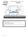
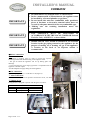
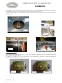
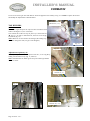
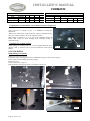
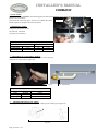
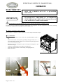
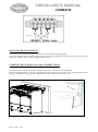
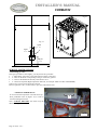
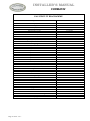
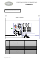
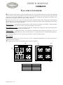
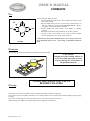
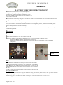
INSTALLER’S MANUAL CORMATIN Table 3 Top burners 5000 11000 15000 18000 GAS Pressure 6" WC 0.90 1.30 1.45 1.70 Natural gas 0.90 1.05 1.20 L.P. propane 10" WC 0.65 Table 4 Top burners 5000 11000 15000 18000 GAS Pressure Oppening / inches Natural gas 6" WC 2,5 / 1/8 2,5 / 1/8 max 7 / 1/4 max max max L.P. propane 10" WC 3,5 / 1/8 Adjustment of reduced flow rate of surface burners (Figure 17): After connection or change of gas, it is crucial to modify this adjustment. -Remove the control knob. Light the burner, adjust to minimum setting, then use a small screwdriver to set the adjusting screw J. Note: Flame is reduced to ¼ of its size in the minimum setting, the burner must remain lit when changing from maximum setting to minimum setting. Refitting the cooking surface: When refitting the cooking surface, it is vital to tighten fastening screws (figures 6 and 7). Failure to do so can cause distortion of the cooking surface. J Fig. 17 OVEN BURNERS: Dismounting oven burner Remove the oven sole (Fig.18). CAUTION: when refitting place the base underneath the groove on the fascia (fig.19). Unscrew the screw K holding the burner (Fig.20). Remove the tray. Unscrew the screw L (Fig.21). Push the burner to the bottom of the oven and lift to remove it. Fig. 19 Fig. 18 L Fig. 20 Page 11 of 40 – US – K Fig. 21