1
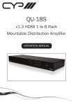
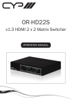
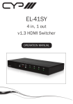
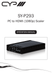
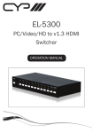
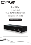
QU-210S
v1.3 HDMI 2 to 10 Rack
Mountable Distribution
Amplifier
OPERATION MANUAL
Table of Contents
1.
Introduction
1
2.
Features
1
3.
Operation Controls and Functions
2
Front Panel Diagram
2
4.
Connection Diagram
4
5.
Specifications
5
3.1
1. Introduction
The QU-210S Distribution Amplifier (splitter) accepts two HDMI inputs and splits
either of these switchable inputs to ten identical outputs. This device is compatible
to v1.3 HDMI specifications, supporting ‘Deep Colour’ together with High Definition
Audio. Each buffered output can run 1080p/8-bit up to 20 metres and can also be
cascaded up to 3 layers.
2. Features
• Compliant with v1.3 HDMI, HDCP 1.1 and DVI 1.1 standards
• HDMI 2 to 10 Splitter
• Resolutions supported: PC - VGA to UXGA; HDTV - 480i to 1080p plus
1080p24fps
• High Definition Audio supported: Dolby TrueHD, Dolby Digital Plus and DTS-HD
Master Audio plus LPCM (32-192KHz sample rate)
• Auto signal amplification & equalisation improves signal transmission distances
• Supports CEC bypass
• Supports Deep Colour (10 & 12 bit)
• Selectable EDID settings - TV (downstream) and STD (fixed)
• Power, HDMI/DVI, HDCP & SYNC plus independent output LED’s indicator
• Supports xvYCC
• Supports 3D signals
Page 1
3. Operation Controls and Functions
3.1 Front Panel
4
HDMI / DVI
KEY LOCK
HDCP
SYNC
OUTPUT
5
4
3
2
1
10
9
8
7
6
2
1
INPUT
POWER
7
8
QU-210S
1
2
3 5
6
1. Remote Control Sensor.
2. Key Lock: Press and hold the ‘Key Lock’ button for 5 seconds. The system will
enter Key Lock mode and the LED indicator will illuminate. When the system is
in Key Lock Mode, all functionality of the buttons will be disabled.
3. HDMI/DVI Indicator: The LED will illuminate when the selected HDMI input is
connected to a HDMI source. The LED will not illuminate when the HDMI input
is connected to a DVI source.
4. HDCP Indicator: The LED indicator will illuminate when the HDMI input source
is HDCP protected.
5. SYNC Indicator: The LED indicator will illuminate when the selected HDMI
Input successfully connects to an HDMI or DVI source.
6. HDMI Output Indicator: The LED will illuminate when the output sources are
connected.
7. HDMI Input Indicator: Press the ‘INPUT’ button repeatedly to switch your
desired Input (HDMI 1 or HDMI 2). The LED indicator will illuminate to indicate
which input source is selected.
8. POWER Indicator: The Power LED will illuminate in Green when the power is
On, and Red when in Standby Mode.
Page 2
3.2 Rear Panel
2
RS-232
HDMI OUT
EDID
1
HDMI IN
2
1
2
3
4
5
DC 5V
6
7
8
9
10
STD TV
1
3
4
5
1. EDID Control Switch: Default setting is TV (downstream). In this mode the
QU-210S will search all output ports (starting at output 1) for the highest
video/audio settings connected to each of the outputs. The detection priority
of the matrix is v1.3 HDMI, v1.2 HDMI, DVI. Switch to STD (fixed EDID) if
you have any issues with the default setting (TV). When switching to STD,
please ensure that the unit is powered OFF, then ON again, for the setting to
be made. By changing to STD, this will force the source to be configured as
standard stereo (PCM) Audio and initiate a search for a common compatible
video resolution.
2. RS-232: 9-Pin D-sub connection for connecting your PC or other RS-232
Control based console for remote operation.
3. HDMI Inputs 1 and 2: Connect input ports to the HDMI or DVI output of your
source equipment such as a Blu-Ray player or set-top box.
4. HDMI Outputs 1 to 10: Connect each of the output ports to the HDMI display.
When more than one output is connected, the HDMI outputs play an identical
video signal simultaniously.
5. POWER: Plug the 5V DC power supply into the splitter and connect the
adaptor to the AC wall socket.
Page 3
4. Remote Control
POWER
1. Power: Press the button to turn the unit ON
or OFF.
1
2
2. Input Select for HDMI: Press ‘1’ to select
HDMI Input 1, or Press ‘2’ to select HDMI
Input 2.
CR-37
5. RS-232 Protocol
5.1 Pin Definitions
The connection between the Splitter and Remote Controller with RS-232 Cable.
QU-210S
PIN
1
2
3
4
5
6
7
8
9
Remote Control Console
Definition
NC
TxD
RxD
NC
GND
NC
NC
NC
NC
* RS-232 transmission format:
Baud Rate: 9600bps
Data Bit: 8 bits
Parity: None
Stop Bit: 1 bit
Flow Control: None
→
←
Page 4
PIN
1
2
3
4
5
6
7
8
9
Definition
NC
RxD
TxD
NC
GND
NC
NC
NC
NC
5.2 Commands
COMMAND
Power 00
Power 01
Port 01
Port 02
ACTION
Power OFF (Standby)
Power ON
Select Input 1
Select Input 2
Page 5
4. Connection Diagram
Page 6
5. Specifications
Input
Output
Power Supply
Dimensions (mm)
Gross Weight (g)
Net. Weight (g)
Chassis Material
2 x HDMI
10 x HDMI
5V/6A DC (US/EU standards, CE/FCC/UL certified)
435(W) x 160(D) x 45(H)
2120
1760
Aluminium
Colour
Operating Temperature
Black
Operating from 0°C ~ 40°C
Page 7
www.cypeurope.com