1
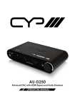
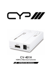
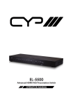
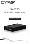
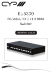
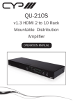
PU-8H8HBT 8 x 8 HDMI HDBaseT™ Matrix (inc. PoE) OPERATIONS MANUAL DISCLAIMERS The information in this manual has been carefully checked and is believed to be accurate. CYP (UK) Ltd assumes no responsibility for any infringements of patents or other rights of third parties which may result from its use. CYP (UK) Ltd assumes no responsibility for any inaccuracies that may be contained in this document. CYP (UK) Ltd also makes no commitment to update or to keep current the information contained in this document. CYP (UK) Ltd reserves the right to make improvements to this document and/or product at any time and without notice. COPYRIGHT NOTICE No part of this document may be reproduced, transmitted, transcribed, stored in a retrieval system, or any of its part translated into any language or computer file, in any form or by any means—electronic, mechanical, magnetic, optical, chemical, manual, or otherwise—without express written permission and consent from CYP (UK) Ltd. © Copyright 2011 by CYP (UK) Ltd. All Rights Reserved. Version 1.1 August 2011 TRADEMARK ACKNOWLEDGMENTS All products or service names mentioned in this document may be trademarks of the companies with which they are associated. SAFETY PRECAUTIONS Please read all instructions before attempting to unpack, install or operate this equipment and before connecting the power supply. Please keep the following in mind as you unpack and install this equipment: • Always follow basic safety precautions to reduce the risk of fire, electrical shock and injury to persons. • To prevent fire or shock hazard, do not expose the unit to rain, moisture or install this product near water. • Never spill liquid of any kind on or into this product. • Never push an object of any kind into this product through any openings or empty slots in the unit, as you may damage parts inside the unit. • Do not attach the power supply cabling to building surfaces. • Use only the supplied power supply unit (PSU). Do not use the PSU if it is damaged. • Do not allow anything to rest on the power cabling or allow any weight to be placed upon it or any person walk on it. • To protect the unit from overheating, do not block any vents or openings in the unit housing that provide ventilation and allow for sufficient space for air to circulate around the unit. REVISION HISTORY VERSION NO. DATE SUMMARY OF CHANGE RDV1 Preliminary Release 21/05/2012 CONTENTS 1. Introduction�������������������������������������������6 2. Applications�������������������������������������������6 3. Package Contents����������������������������������6 4. System Requirements���������������������������6 5. Features��������������������������������������������������7 6. Operation Controls and Functions�������8 6.1 Front Panels������������������������������������������������� 8 6.2 Rear Panels��������������������������������������������������� 9 6.3 Side Panel���������������������������������������������������10 6.4 Remote Control����������������������������������������10 6.5 IR Pin Assignment������������������������������������11 6.6 RS-232 Protocols��������������������������������������12 6.7 RS-232 Commands����������������������������������13 7. Connection Diagram�������������������������� 14 8. Specifications�������������������������������������� 16 9. Acronyms��������������������������������������������� 17 1. INTRODUCTION s the Flagship 8x8 HDBaseT™ Matrix, the PU-8H8HBT solution offers A complete HDBaseT™ convergence. Installers can switch and distribute up to 8 HDMI sources, RS-232, 2-Way IR, and PoE to lengths of up to 100m using CAT5e/6 cable infrastructure. This single box solution will enable an installer to confidently integrate an eight zone multi-room AV system. The PU-8H8HBT is designed to be used with the PU-507-RX Receiver which can utilise the Power over Ethernet (PoE) capabilities of the matrix. 2. APPLICATIONS HDMI System controls Video/TV wall display and control Security surveillance and control Commercial advertising, displaying and control Lecture room display and control Hyper market demonstration and control 3. PACKAGE CONTENTS 8×8 HDMI Matrix Switcher over CAT5e/6/7 HDMI over CAT5e/6/7 Receiver (Optional) 2×IR Extender 2×IR Blaster 2×24 V/6.25 A DC Power Adaptor (1 for PoE) 1×IR Remote control Operation manual 4. SYSTEM REQUIREMENTS Input source equipment with HDMI connection cables, industry standard CAT5e/6/7 cables Output display or audio receiver equipments with HDMI connection cables HDMI over CAT5e/6/7 Receiver(s) 6 5. FEATURES Supports all v1.3 HDMI resolutions Supports uncompressed video/audio up to 10.2Gbps Common supported resolutions: HDTV: 480p, 576p, 720p, 1080i, 1080p, 1080p24; PC: VGA, SVGA, XGA, WXGA, SXGA, UXGA, WUXGA. HDMI, HDCP and DVI complaint High Definition Audio supported: Dolby TrueHD, Dolby Digital Plus and DTS-HD Master Audio plus LPCM (up to 192kHz) Uncompressed data transfer over single CAT cable (100m - CAT6; 80m CAT5e) Supports HDMI input up to 15m 1080p 8bit or 10m 1080p 12bit. Supports RS-232, 2-Way IR, Manual Selection Buttons, and HDMI CEC control pass through Selectable EDID settings - TV (downstream) and STD (fixed). Compact 2U Rack mount design Supports 3D signals Supports additional IR Control via a master (ALL) Input/Output. Note: The PoE function is designed for powering compatible receiver units only—non-PoE receivers will need their own power supply.Receivers of another brand may not be compatible. 7 6. OPERATION CONTROLS AND FUNCTIONS 6.1 Front Panels MENU POWER 1 2 A 1 B 2 C 3 D 4 OUT E 5 F 6 G 7 H 8 IN LOCK 3 4 5 6 1 LCD Display: Displays the setting information of each input and output selection. 2 Power button LED: Press this button to power the device on/off. The LED will illuminate green when the power is on, red when it is in 'Standby' mode. 3 LOCK: Press this button to lock all the buttons on the panel, press again to unlock. The LED will illuminate green when locked. 4 IR: IR Receiver window (accepts the remote control signal of this device only). 5 MENU: Press this button to change the EDID setting from STD (internal) 1 to TV (external) 2 , press it again to confirm the selection. 6 1~8/A~H and Out/In button: Press the Out or In button to select the output or input mode then press the required number button to make the selection accordingly. For example, if outputs A~D need to be set to input 1 and outputs E~H need to be set to input 2 then the following sequence of button presses need to be performed Press: Out ABCDIn1Menu, and then press: OutEFGHIn2Menu. Note: If the menu button is not pressed the selection will not be changed. 8 6.2 Rear Panels 3 6 9 V+ ALL IR OUT IR OUT A IR OUT IR IN B IR OUT IR IN IR IN C IR OUT CAT5e/6 OUT CAT5e/6 OUT CAT5e/6 OUT LAN IR IN D IR OUT CAT5e/6 OUT IR IN E IR OUT CAT5e/6 OUT IR IN F IR OUT CAT5e/6 OUT IR IN G IR OUT CAT5e/6 OUT IR IN H GND CAT5e/6 OUT GND 3 4 1 2 V+ GND POE 24V IR IN RS232 SERVICE 1 HDMI IN 1 2 4 5 7 2 HDMI IN 3 HDMI IN 4 HDMI IN 5 HDMI IN 8 6 HDMI IN 7 HDMI IN 8 HDMI IN MAIN 24V 10 11 1 LAN: Reserved. 2 RS-232: Connect to a PC or laptop with D-Sub 9-pin female cable for the transmission of RS-232 commands. 3 MATRIX IR OUT: Connect to the IR blaster (included in the package) for transmitting IR signals to the source or display equipment. Place the IR blaster in direct line-of-sight of the equipment to be controlled 4 MATRIX IR IN: Connect to the IR extender (included in the package) for the reception of IR signals from the remote control of this device or the source and display equipment. Ensure that remote being used is within the direct line-of-sight of the IR extender. 5 SERVICE: This slot is to connect with mini USB-B type cable for firmware update only. 6 IR IN 1~8: Connect the supplied IR extenders (included in the package) for IR signal reception. Ensure that remote being used is within the direct line-of-sight of the IR extender 7 IR OUT 1~8: Connect the supplied IR blasters (included in the package) for IR signal transmission. Place the IR blaster in direct line-of-sight of the equipment to be controlled. 8 CAT5e/6/7 OUT 1~8: Connect to the Receiver units with a single CAT5e/6/7 cable from the Receiver for HDMI Audio/Video and IR/RS232 control. 9 HDMI IN 1~8: Connect to the HDMI input source devices such as a DVD player or a Set-top Box with HDMI cable or DVI to HDMI converter cable. 10 PoE 24V: This slot is to plug the power cord with adaptor included in the package and then connect them with AC wall outlet for power supply, for powering receivers with Power-over-Ethernet capability. 11 DC 24V MAIN POWER: This slot is where user connect the 24V DC power adaptor included in the package and plug the adaptor to an AC wall outlet for power supply, for powering the main unit. 9 6.3 Side Panel 1 1 Fan Ventilator: These are air ventilation areas, DO NOT block these areas or cover it with any object. Please allow adequate space around the unit for air circulation 6.4 Remote Control 1 Power: Press this button to switch on the device or set it to standby mode. 1 2 IN: Input ports selection 1~8. 3 OUT: Output ports selection A~H. 2 10 3 6.5 IR Pin Assignment IR Blaster 1 Power 5 V 2 IR Blaster Signal 3 NC IR Receiver 1 IR Signal 2 Power 5 V 3 Grounding 11 6.6 RS-232 Protocols Pin Assignment CMSI-8H8CV Remote Control Console PIN Assignment PIN Assignment 1 NC 1 NC 2 Tx 2 Rx 3 Rx 3 Tx 4 NC 4 NC 5 GND 5 GND 6 NC 6 NC 7 NC 7 NC 8 NC 8 NC 9 NC 9 NC Baud Rate: 19200bps Data bit: 8 bits Parity: None Stop Bit: 1 Flow Control: None 12 6.7 RS-232 Commands Command (Case Sensitive) Description A1~A8 Switch output A to 1~8 B1~B8 Switch output B to 1~8 C1~C8 Switch output C to 1~8 D1~D8 Switch output D to 1~8 E1~E8 Switch output E to 1~8 F1~F8 Switch output F to 1~8 G1~G8 Switch output G to 1~8 H1~H8 Switch output H to 1~8 ABCD...1~ABCD...8 Switch output ABCD... to 1~8 at the same time P0 POWER OFF P1 POWER ON I1~I8 Switch all the output to 1~8 ST Display the current matrix status and F/W version RS System Reset to A1, B2, C3, D4, E5, F6, G7, H8 ? Display all available commands 13 7. CONNECTION DIAGRAM ZONE A RX Power ZONE B RX Link IR 2 IR 1 Extender Blaster RS232 Out CAT5e/6 In Power ZONE C Link IR 2 IR 1 Extender Blaster RS232 Out CAT5e/6 In RX Power ZONE D RX Link IR 2 IR 1 Extender Blaster RS232 Out CAT5e/6 In Power R Link IR 2 IR 1 Extender Blaster RS232 Out CAT5e/6 In IR In (ALL) ALL IR OUT IR OUT IR IN IR IN A IR OUT CAT5e/6 OUT LAN B IR OUT CAT5e/6 OUT IR IN C IR OUT CAT5e/6 OUT D IR OUT CAT5e/6 OUT IR IN IR IN E CAT5e/6 OUT IR IN RS232 SERVICE IR Out (All) RS232 Equipped PC or Notebook 1.5m 60° 3m 7m m 3m IR RECEIVER 60° IR BLASTER 1 HDMI IN 2 HDMI IN 3 HDMI IN 4 HDMI IN 5 HDMI IN 1 2 3 4 5 ZONE E ZONE F ZONE G ZONE H Displays HDMI Outputs IR Out/In RX Power RX Link IR 2 IR 1 Extender Blaster RS232 Out CAT5e/6 In Power Link IR 2 IR 1 Extender Blaster RS232 Out CAT5e/6 In RX Power Link IR 2 IR 1 Extender Blaster RS232 Out CAT5e/6 In RX Power Link IR 2 IR 1 Extender Blaster RS232 Out CAT5e/6 In Receiver Units Single CAT 5e/6 Cable V+ IR OUT F IR OUT CAT5e/6 OUT IR IN G IR OUT CAT5e/6 OUT IR IN H GND CAT5e/6 OUT GND 3 4 1 2 V+ GND POE 24V IR IN Power Supply for Power-over-Ethernet 6 HDMI IN 7 HDMI IN 8 HDMI IN 6 7 8 MAIN 24V Main Power Supply HDMI Inputs IR Out/In Source Equipment 8. SPECIFICATIONS Max. TMDS Bandwidth 6.75 Gbps Input Ports 8×HDMI, 9×IR Extender, 1×RS-232, 1×Mini USB-B type(for firmware update only) Output Ports 8×CAT5e/6/7, 9×IR Blaster ESD Protection Human body model: ± 8kV (Air-gap discharge) ± 4kV (Contact discharge) Power Supply 24 V/6.25 A DC (US/EU standards, CE/ FCC/UL certified) Dimensions 438 mm(W)×255 mm(D)×93 mm(H) Weight 4458 g Chassis Material Metal Silkscreen Color Black Operating Temperature 0 ºC~40 ºC/32 ºF~104 ºF Storage Temperature −20 ºC~60 ºC/−4 ºF~140 ºF Relative Humidity 20~90 % RH (non-condensing) Power Consumption 64 W Tx(Main), 56 W Rx(PoE) 9. ACRONYMS ACRONYM COMPLETE TERM DTS Digital Theater System DVI Digital Visual Interface EDID Extended Display Identification Data HDCP High-bandwidth Digital Content Protection HDMI High-Definition Multimedia Interface HDTV High-Definition Television LCM Liquid Crystal Monitor USB Universal Serial Bus UXGA Ultra Extended Graphics Array VGA Video Graphics Array CYP (UK) Ltd., Unit 7, Shepperton Business Park, Govett Avenue, Shepperton, Middlesex, TW17 8BA Tel: +44 (0) 20 3137 9180 | Fax: +44 (0) 20 3137 6279 Email: [email protected] www.cypeurope.com