1
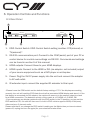
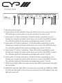
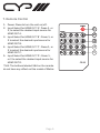
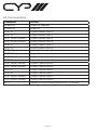
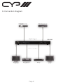
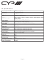
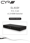
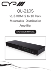
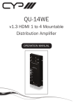
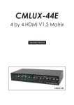
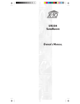
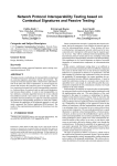
OR-HD24S
v1.3 HDMI 2 x 4 Matrix Switcher
OPERATION MANUAL
Precautions
Failure to follow the precautions described below may cause damage to this v1.3
HDMI Matrix and void the warranty.
• DO NOT open the case. This will void the warranty, if you find a problem with
this product, please return it to your retailer or seller who will assist you or
provide you with a solution.
• DO NOT use third-Party AC adaptors or power cords. This may damage the
Matrix.
• DO NOT bump, jar or drop the product because it may cause damage and void
the warranty.
• DO NOT allow liquids to come into contact with the Matrix because they may
cause damage.
Table of Contents
1.
Introduction
1
2.
Application
1
3.
Package Contents
1
4.
System Requirements
2
5.
Features
2
6.
Operation Controls and Functions
3
6.1
Rear Panel
3
6.2
Front Panel
4
7.
Remote Control
5
8.
RS-232 Protocol
6
8.1
Command Sets
7
9.
Connection Diagram
8
10.
Specifications
9
Finden Sie ab Seite 9.
1. Introduction
Thank you for purchasing this v1.3 HDMI Matrix. As HDMI products become
increasingly popular, users often have multiple HDMI sources and displays.
This HDMI matrix provides an excellent and convenient solution for connecting
all your HDMI equipment. You can select which source to view on each of the
displays using the remote control. This matrix can also transfer deep colour
video and bitstream audio with maximum performance. It supports v.1.3 HDMI,
HDCP 1.1 and DVI 1.0.
Please follow this manual to start enjoying the benefits of this Matrix. We
suggest you keep it in a safe place for future reference.
2. Application
• High performance v1.3 HDMI Matrix with 2 inputs and 4 outputs including a
remote for Infra red control, allowing you to link all your favourite HDMI devices
and enjoy your music, movies and games.
• Each of the two HDMI sources can be simultaneously directed to any of the four
HDMI Displays independently (e.g one source to screen 2, the other to screen 4).
• As the HDMI signal progresses through the system, it is re-timed, and levelcompensated.
• The HDCP & HDMI/DVI LEDs will illuminate accordingly to define the input
source’s format.
• Switchable EDID function, choose between built in EDID or read the external
EDID of connected display.
3. Package Contents
• OR-HD24S v1.3 HDMI Matrix.
• CR33 Remote Control (with Battery)
• IR Receiver
• Power Cord
• 5V DC power supply adaptor.
• Operation Manual.
Page 1
4. System Requirements
HDMI source device(s) and HDMI display device(s).
5. Features
• v1.3 HDMI, HDCP 1.1 and DVI 1.0 compliant.
• Supports digital video formats in Deep Colour 12bit and new lossless digital
audio (Dolby TrueHD, Dolby Digital Plus and DTS-HD Master Audio).
• The HDMI input is compensated, clock / phase adjusted and jitter eliminated
so the output is a brand new standard HDMI signal.
• LEDs on each output to indicate which input is currently selected.
• Compatible with all HDMI sources and displays.
• Supports a wide range of PC and HDTV resolutions from VGA to UXGA
• and 480i to 1080p including 1080p24fps.
• Supports RS-232 control.
• Supports IR remote control and IR extender (via 3.5mm jack IR input).
• Dolby Digital, DTS digital audio transmission (32-192 kHz Fs sample rate).
• Supports LPCM7.1 channel audio from each independent HDMI output.
• At 1080p/8bit resolution, source to input cable length can be up to 10m,
output to display cable length can be up to 10m.
• At 1080p/12bit, the source to input cable length can be up 10m, Output to
display cable can run up to 6 metres.
Page 2
6. Operation Controls and Functions
6.1 Rear Panel
2
RS-232
HDMI OUTPUT
EDID
STD
D
C
DC 5V
HDMI INPUT
B
A
2
IR
1
TV
1
3
4
5 6
1. EDID Control Switch: EDID Control Switch setting is either: STD(internal) or
TV(external)*
2. RS-232 communication port: Connect to the COM (serial) port of your PC or
control device for control over settings via RS-232. Commands and settings
can be found in section 9 of this manual.
3. HDMI outputs: Connect these to your HDMI displays.
4. HDMI inputs: Connect to the HDMI or DVI (via adaptor- not included) output
of your source equipment such as a DVD player or set-top-box.
5. Power: Plug the 5V DC power supply into the unit and connect the adaptor
to AC wall outlet.
6. IR extender input- connect the supplied IR extender to this input.
*Please Leave the EDID switch on the default factory setting of ‘TV’ if the displays are working
correctly, the unit will read the EDID data from the first connected HDMI display and store it. If the
first device is connected via DVI adaptor, the matrix will move on to the second output to check
for a HDMI connection. The detection priority of the matrix is v1.3 HDMI, v1.2 HDMI, DVI.
*If you experience any display problems with the EDID switch in the TV position, you can set the
EDID switch to STD, the unit will then use it’s built in EDID- which supports 1080p 12bit(max)
video and pcm 2 channel audio.
Please note that If you change the EDID switch’s setting on the Matrix then you have to reboot
(power off, unplug and turn on again) for your selection to take effect.
Page 3
6.2 Front Panel
1
2
HDCP HDMI/DVI
A
1
2
HDMI OUT
1
2
HDCP HDMI/DVI
1
2
HDCP HDMI/DVI
B
3
INPUT
INPUT
INPUT
INPUT
POWER
C
4
5
HDMI OUT
1
2
HDCP HDMI/DVI
D
6 7 8
1.Remote control sensor
2.Power switch & LED indicator: Press the button to turn the unit on/off, the
LED lights green when power is on and red when the power is off.
3.Input select ‘A’ button/indicators: Press this button repeatedly to cycle
through your inputs and select which source to route to the HDMI A output.
The indicator lights will illuminate accordingly (see points 7 and 8).
4.Input select ‘B’ button/indicators : Press this button repeatedly to cycle
through your inputs and select which source to route to the HDMI B output.
The indicator lights will illuminate accordingly (see points 7 and 8).
5.Input select ‘C’ button /indicators : Press this button repeatedly to cycle
through your inputs and select which source to route to the HDMI C output.
The indicator lights will illuminate accordingly (see points 7 and 8).
6.Input select ‘D’ button/indicators : Press this button repeatedly to cycle
through your inputs and select which source to route to the HDMI D output.
The indicator lights will illuminate accordingly (see points 7 and 8).
7.HDCP source light: When the input source has HDCP implemented this light
will illuminate.
8.HDMI/DVI indicator light: When the source is connected via HDMI the HDMI/
DVI LED will illuminate. If the source is connected via a DVI adaptor then the
light will remain off.
Page 4
7. Remote Control
1. Power: Press to turn the unit on/off.
2. Input Select for HDMI OUT ‘A’: Press 1, or
2, to select the desired input source for
HDMI OUT A.
3. Input Select for HDMI OUT ‘B’: Press 1, or
2 to select the desired input source for
HDMI OUT B.
4. Input Select for HDMI OUT ‘C’: Press 1, or
2 to select the desired input source for
HDMI OUT C.
5. Input Select for HDMI OUT ‘D’: Press 1,
or 2 to select the desired input source for
HDMI OUT D.
*N.B: The buttons labeled 3&4 on the remote
do not have any effect on this model of Matrix.
Page 5
POWER
OUTPUT
1
2
A
OUTPUT
3
B
OUTPUT
4
C
OUTPUT
5
D
CR-33
8. RS-232 Protocol
OR-HD22S
Remote Control Console
PIN
Definition
PIN
Definition
1
2
3
4
5
6
7
8
9
NC
Tx
Rx
NC
GND
NC
NC
NC
NC
1
2
3
4
5
6
7
8
9
NC
Rx
Tx
NC
GND
NC
NC
NC
NC
→
←
Baud Rate: 9600bps
Data bit: 8bits
Parity: None
Stop bit: 1bit
Flow Control: None
Page 6
8.1 Command Sets
COMMAND
POWER 00
POWER 01
PORT 11
PORT 12
PORT 13(No Function)
PORT 14(No Function)
PORT 21
PORT 22
PORT 23(No Function)
PORT 24(No Function)
PORT 31
PORT 32
PORT 33(No Function)
PORT 34(No Function)
PORT 41
PORT 42
PORT 43(No Function)
PORT 44(No Function)
ST
ACTION
Power Off (standby)
Power On
Output A select Input 1
Output A select Input 2
Output A select Input 3
Output A select Input 4
Output B select Input 1
Output B select Input 2
Output B select Input 3
Output B select Input 4
Output C select Input 1
Output C select Input 2
Output C select Input 3
Output C select Input 4
Output D select Input 1
Output D select Input 2
Output D select Input 3
Output D select Input 4
Display the current matrix status and F/W version
Page 7
9. Connection Diagram
Page 8
10. Specifications
Frequency bandwidth
Input ports
Output ports
EDID
HDMI Audio output
HDMI Cable in
HDMI Cable out
Color Space
IR
Deep Color
HDMI Resolution
DVI Resolution
Power Supply
Dimensions (mm)
Weight (g)
Chassis Material
Silk Skin Color
Operating Temperature
Power Consumption
2.25Gbps (single link)
2 x HDMI female ports,
4 x HDMI female ports
Standard, TV/Moving Port 1
PCM2, PCM5.1, PCM7.1, Dolby5.1, DTS5.1, Dolby Digital+, Dolby
TrueHD, DTS-HD
1080p 8bit (10m), 1080p 12bit (10m)
1080p 8bit (10m), 1080p 12bit (6m)
RGB_24/36,YCbCr 4:4:4_24/36, YCbCr 4:2:2,xvycc
Yes
1080p 12bit
480I~1080p 50/60, 1080p 24, VGA~UXGA
480I~1080p 50/60, 1080p 24, VGA~UXGA
5VDC/6A (US/EU standards, CE/FCC/UL certified)
438(W) x 175(D) x 49(H)
3100
Metal
Black
Operating from 0°C ~ 40°C
8W(Max)
Page 9
Notes:
Page 10
www.cypeurope.com