1
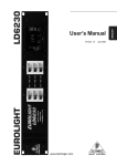
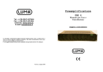
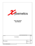
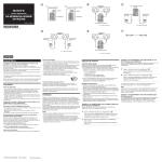
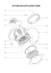
Menu
164 320 12 - UP12 OIL 12 V
164 320 13 - UP12 OIL 24 V
ELETTROPOMPA AUTOADESCANTE PER TRAVASO
DI OLII LUBRIFICANTI O DI LIQUIDI VISCOSI
SELF PRIMING ELECTRIC PUMP
FOR TRANSFERRING LUBRICATING OILS
OR VISCOUS FLUIDS
23/03/07 Ed.00 Rev.01
AVVERTENZE D’USO
INSTRUCTIONS FOR USE
ENG
PRODUCT DESCRIPTION
A
Self-priming electric particularly designed for the transfer of lubricating oils or viscous
liquids (see chapter of exclusions), for discontinuous use.
The pumping elements are made up of bronze gear drives which can possibly even run
dry for brief periods.
TECHNICAL DETAILS
B
CODICE
TIPO
VOLT FUSIBILE PORTATA FLOW RATE PESO P.ZI x CART.
CODE
TYPE
VOLT
FUSE
ø 12 mm
ø 16 mm WEIGHT PCS x CART.
164 320 12 UP12/OIL
12
15 A
360 l/h
900 l/h
4,1 kg
6
164 320 13 UP12/OIL
24
7,5 A
360 l/h
900 l/h
4,1 kg
6
AMBIENT CONDITIONS
C
Ambient operating conditions:
Temperature: min. -10 °C / max. +60 °C Relative humidity: max. 90 %
Warning: the above indicated temperature ranges are applicable to all components of the
pump and these limits must be respected in order to avoid any possible damage or
malfunctioning.
ELECTRICAL CONNECTIONS
D
The electric pump must be connected to a source of direct current (either battery or
transformer) with an amp rating of over 15A and 7,5A at nominal voltage of 12V and 24V
respectively. The pump must be protected by a suitable rated fuse.
OPERATING CYCLE
E
The pump has been designed for discontinuous use. Under conditions of high operating
pressures (eg. with closed or blocked outlet, excessive length of the delivery circuit and/or
excessive pressure due to accessories), the pump can be subjected to elevated stresses
and overheating and therefore should not be used for prolonged periods under such
conditions.
APPLICATIONS
F
There are numerous fields of applications for the pump, however only exclusively with
the allowed liquids mentioned:
- transfer of lubricating oil
- transfer of viscous liquids
- transfer of oils, antifreezing
- circulation of viscous liquids
- draining of engine sumps
FLUIDS ALLOWED / NOT ALLOWED
G
ALLOWED:
FRESH WATER
ENGINE OIL AND NON-CORROSIVE VISCOUS LIQUIDS, max viscousity 85 cst
DIESEL FUEL, max temperature 80°C
NOT ALLOWED:
RELATED DANGERS
PETROL (GASOLINE)
FLAMMABLE LIQUIDS with PM < 55°C
FOODSTUFF LIQUIDS
CORROSIVE CHEMICAL PRODUCTS
FIRE EXPLOSION
FIRE EXPLOSION
FOODSTUFF LIQUID CONTAMINATION
PUMP CORROSION INJURY TO PERSONNEL
FIRE EXPLOSION
DAMAGE TO SEALS
SOLVENTS
H
TRANSPORTATION AND HANDLING
Due to limited weight and dimensions the pump does not require the use of any special
handling or lifting equipment. When handling manually, normal personal protective gear
should be worn (safety shoes with toe piece, etc.)
The pump is carefully packed prior to shipment. Upon receiving, the pump packaging
should be inspected for damages and the pump stored in a dry area.
I
INSTALLATION
It is recommended that the use of the pump be according to normative safety
standards and also as per the precautions listed below.
I-1
PACKAGING ENVIRONMENTAL DISPOSAL
The packing material does not require special disposal precautions, as it is not polluting or
dangerous. The user is anyway invited to effect a proper waste separation, in order to
facilitate the recycling of the materials of which the packing is composed.
I-2
PRELIMINARY CHECKS
Check that there has been no damage to the pump during transportation or storage. Both
inlet and outlet ports should be carefully cleaned removing possible dust or residual
packaging material. Verify that the available electrical power supply corresponds to the
pump specification requirements.
I-3
POSITIONING OF THE PUMP
The pump can be mounted in any position. Fix the pump utilizing suitable screws
corresponding to the antivibration mounts supplied with the pump.
ENG
WARNING: THE PUMP MOTOR IS NOT EXPLOSION PROOF. Do not install the pump
where flammable vapours or gases may be present. Install the pump in an accessible
place for inspection.
The pump is IP55 protection rated. It is good practice to avoid any pump contact with water
splashes possibly causing water seepage into the motor with high risk of internal oxidation
and/or short circuit.
TUBING CONNECTIONS
I-4
- Prior to making any tube/hose connections, check that the inlet ports have no end caps.
- Do not position the pump at a height greater than 2 m with respect to the minimum level of
the fluid to be transferred. Pump damage may occur if this height is exceeded as the pump
may not draw fluid. Make sure that the outlet tube is empty and without chokes.
- Avoid choking the inlet or outlet tubes so that pump efficiency is optimized. The use of an
inlet filter is mandatory especially with fluids containing impurities (filter grid gauge
0,5mm). In this case frequent cleaning and maintenance of the filter is advisable. Utilize
tubes and connection pieces that are resistant to the fluid types handled and avoid any
possible environmental dispersion.
PUMP INSTALLATION
I-5
The electrical installation of the pump must include a protection fuse which is suitably
rated as indicated on the motor label and sized with reference to the chosen point of
application.
WARRANTY
EXPIRES
IF
NO
FUSE
IS
UTILIZED
Always mount the anti vibration rubber fittings supplied with the pump kit. Their usage
ensures a consistent reduction in noise and vibration levels.
Electrical cabling size should depend on the distance between pump and battery power
supply.
Up to 5 m length: 4 mmq
Over 5 m length: 6 mmq
The use of undersized cabling can cause overheating of the electrical wiring and
subsequent fire hazard. There will also be a voltage drop at the motor terminals with a
consequent reduction in efficiency.
The flow rate value indicated on the motor label is obtained with a 16 mm internal tube
diameter. Tubes with inferior diameters will cause an increase in current with potential risk
of motor overheating.
To ensure the correct directional flow of the fluid as indicated by the arrow on the top of the
pump, it is necessary to connect the positive pole of the battery supply to the red wire ( + )
on the motor end-cap and the negative pole to the black wire ( - ). Electrical connections
must be made using adequate terminal blocks and connectors ensuring a tight fitment of
the electrical cables. Bad wiring can cause power losses and/or overheating of the cabling
itself.
WARNING: it is the responsibility of the installation technician to ensure a correctly
designed circuit installation fitted according to regulations. Environmental risks must be
taken into account with the installation.
L
L-1
TROUBLESHOOTING
CHECK POINTS IF THE PUMP HAS STOPPED OR WILL NOT START
- Check the effectiveness of the battery power supply (voltage activity)
- Check if the fuse has blown
- Check for any foreign matter present in-between the pump gear drives. To do this,
disconnect the power supply and unscrew the four fixing screws, remove the pump front
cover plate and inspect the pump chamber. Replace the cover plate in the same initial
position after inspection.
- Avoid running the pump dry for more than a few minutes. Pumps found defective that
have run dry in the absence of fluid are not covered by warranty.
- The average life span of the motor commutator brushes is approximately 800/1000
hours under normal operating conditions. Stoppages are possible due to brush wear and
tear after such a time period.
L-2
WHY THE PUMP WILL NOT PRIME ITSELF?
- The pump is fitted at a height greater than 2 m above the fluid level.
- The pump has run dry for too long a period
- Long periods of inactivity. In this case it is advisable to add liquid directly into the pump
chamber before start-up. It is also advisable to add, before running the pump, a drop of
lubricating oil inside the pump only.
- Air leak at the suction pipe due to the following reasons:
- Possible cuts in the pipe, inadequate hose clamps, malfunctioning of the filter due to
defective/worn seals or filter clogged.
- Air leak at the pump front plate cover due to the following reasons:
- Loose fixing screws, poor effectiveness of the seal.
- Faulty electrical cable connections
- Presence of obstructions or restrictions in the suction or delivery pipes or the use of
special devices(eg. automatic spray pistol or aqua-stop).
- Presence of liquid loops in the outlet tube.
L-3
GOOD PRACTICES ENSURING A WELL FUNCTIONING PUMP
No particular maintenance is required if the pump is utilized for the transfer of diesel fluids.
If it is expected that the pump will not be used for a period of at least 30 days, especially in
the case of usage with fresh or salty water, it is advisable to run fresh water through the
pump and to then loosen the pump front plate screws.
ENG
Upon re-use, run the pump briefly (a few seconds) and then tighten the screws again.
Check under conditions of maximum operating pressure that the motor current value is
within the motor label specifications.
NORMAL MAINTENANCE
L-4
Check every month the pump chamber and keep clean from any foreign matter.
Check every month that electrical wiring is in good condition.
Every 800 hours of pump operation substitute the motor brushes.
INDICATORS THAT THE PUMP IS FUNCTIONING CORRECTLY
L-5
- Temperature of pump body and motor frame is within 60°C - 70°C
- Regular flow and constant pump noise levels
- Amp-draw within the limits indicated in the technical details.
TO OPEN THE PUMP
L-6
- It is recommended that a specialized service technician be consulted for any pump repair
work or the replacement of worn out internal components, exclusively with original spare
parts.
- During the warranty period, only by authorized Marco S.p.A. personnel, failing which the
warranty will expire.
ENVIRONMENTAL DISPOSAL
M
For a correct disposal of the pump at the end of its life, contact the local waste disposal
service. The proper waste separate collection helps avoiding possible negative effects on
the environment and on everybody’s health. It also facilitates the recycling of the materials
of which the product is composed.
WARRANTY
N
1) The Warranty period is 2 years from date of purchase on production of the
appropriate sales invoice.
2) Should the original sales invoice not be available, then the 2 year warranty period
will be valid from date of production.
3) The Warranty becomes null and void in the case of incorrect utilization or disregard
of the instructions contained herein.
4) The Warranty only covers original production defects.
5) The Warranty does not cover any related installation costs involved.
6) Transport costs are refundable only in the case where warranty has been duly
recognized and accepted by Marco Spa. These costs will be limited to the actual
shipment costs between Marco Spa warehouse and the client's delivery address.
7) No credit notes or replacement items will be issued prior to the receipt and proper
testing of any Marco goods that are deemed faulty.
EXPLODED VIEW
O
15
16
16
14
12
11
17
10
ART. Q.TY DESCRIPTION
1
4 TOP PLATE SCREW M 5 X 10
2
1 TOP PLATE
3
1 TOP PLATE O-RING
4
1 DRIVING GEAR
5
1 IDLE GEAR
6
1 IDLE SHAFT
7
1 PUMP BODY
8
1 RUBBER LIP SEAL
9
1 ARMATURE
10
1 KEY
11
2 ROD
12
1 PUMP FRAME WITH MAGNETS
13
4 ANTIVIBRATION MOUNT
14
1 BRUSH HOLDER
15
2 WASHER
16
2 NUT
17
2 TUBE OUTLET
18
2 O-RING
18
7
8
5
11
9
1
13
13
13
1
18
6
17
4
3
2
1
1
DIMENSIONS
212,5
194,63
58
18
212,5
94
22,55
117
189,95
60
174,3
15,05
108,35
70,05
60,05
38,3
151,95
10
80
17
P
ENG
FLOW RATE DIAGRAM
flow rate (l/min)
20
Ø16
15
Ø12
10
5
0
20
30
40
50
temperature (°C)
ampere-draw (A)
AMPERE-DRAW DIAGRAM
14
12
10
8
6
4
2
0
12V
24V
20
30
40
temperature (°C)
50
MARCO PUMPS LIST
Q
ITEM
DESCRIPTION
ITEM
DESCRIPTION
1620011C UP1 220V a.c. rubber impeller pump 30 l
16430212 UP12/P 12V PTFE gear pump 40 l
16200012 UP1 12V rubber impeller pump 35 l
16430213 UP12/P 24V PTFE gear pump 40 l
16200013 UP1 24V rubber impeller pump 35 l
1640421C UPX 220V a.c. gear pump 10 l stainless-steel version
16200212 UP1-N 12V rubber impeller pump 35l
16404012 UPX 12V gear pump 14 l stainless-steel AISI 316
16200213 UP1-N 24V rubber impeller pump 35l
16404013 UPX 24V gear pump 14 l stainless-steel AISI 316
16420012 UP2 12V gear pump 8 l
1640431C UPX-C 220V a.c. stainless-steel gear pump for chemicals 10 l
16420013 UP2 24V gear pump 8 l
16404112 UPX-C 12V stainless-steel gear pump for chemicals 14 l
16466015 UP2/A 12/24V automatic pump with electronic pressure switch 8 l
16404113 UPX-C 24V stainless-steel gear pump for chemicals 14 l
16422012 UP2/OIL 12V gear pump for lubricating oil
16410112 UP9-XC 12V heavy duty gear pump - s.s. AISI 316
16422013 UP2/OIL 24V gear pump for lubricating oil
16410113 UP9-XC 24V heavy duty gear pump - s.s. AISI 316
16420212 UP2/P 12V PTFE gear pump 8 l
16440112 UP10-XC 12V heavy duty gear pump - s.s. AISI 316 - 18 l
16420213 UP2/P 24V PTFE gear pump 8 l
16440113 UP10-XC 24V heavy duty gear pump - s.s. AISI 316 - 18 l
16420412 UP2-PV 12V PTFE gear pump 8 l + non-return valve
16490015 SP2 12/24V shower pump
16420413 UP2-PV 24V PTFE gear pump 8 l + non-return valve
16480012 DP3 12V deck washing pump
1640031C UP3/AC 220V 50Hz oil / diesel gear pump 10 l
16480013 DP3 24V deck washing pump
1640011C UP3/AC 220V a.c. gear pump 10 l
16482012 DP9 12V deck washing pump
16400012 UP3 12V gear pump 14 l
16482013 DP9 24V deck washing pump
16460215 UP3/E 12/24V automatic pump with electronic pressure switch 14 l
16484012 DP12 12V deck washing pump
16400013 UP4 24V gear pump 14 l
16484013 DP12 24V deck washing pump
16400212 UP3/P 12V PTFE gear pump 14 l
16010012 UP500 12V bilge pump
16400213 UP4/P 24V PTFE gear pump 14 l
16010013 UP500 24V bilge pump
16402012 UP3/OIL 12V gear pump for oil
16012012 UP1000 12V bilge pump
16402013 UP4/OIL 24V gear pump for oil
16012013 UP1000 24V bilge pump
16460012 UP3/A 12V automatic pump group with accumulator
16014012 UP1500 12V bilge pump
16460013 UP4/A 24V automatic pump group with accumulator
16014013 UP1500 24V bilge pump
1640621C UP6/AC 220V a.c. gear pump 28 l
16016012 UP2000 12V bilge pump
1640611C UP6 220V a.c. gear pump 28 l
16016013 UP2000 24V bilge pump
16406012 UP6 12V gear pump 26 l
16406013 UP6 24V gear pump 26 l
16408012 UP6/OIL 12V gear pump for oil
16408013 UP6/OIL 24V gear pump for oil
16462012 UP6/A 12V automatic pump group with accumulator
16462013 UP6/A 24V automatic pump group with accumulator
16410212 UP9-PN 12V internal brushes PTFE gear pump
16410213 UP9-PN 24V internal brushes PTFE gear pump
16410012 UP9 12V heavy duty gear pump
16410013 UP9 24V heavy duty gear pump
16464012 UP9/A 12V heavy duty automatic pump group with accumulator
16464013 UP9/A 24V heavy duty automatic pump group with accumulator
16440012 UP10 12V bronze gear pump 18 l
16440013 UP10 24V bronze gear pump 18 l
16440212 UP10/P 12V PTFE gear pump 18 l
16440213 UP10/P 24V PTFE gear pump 18 l
16468012 UP12/A 12V water pressure pump system
16468013 UP12/A 24V water pressure pump system
16432012 UP12/OIL 12V bronze gear pump 15 l
16432013 UP12/OIL 24V bronze gear pump 15 l
16430012 UP12 12V gear pump 40 l
16430013 UP12 24V gear pump 40 l
IT
ENG
DICHIARAZIONE DI CONFORMITA’ C.E.
E.C. DECLARATION OF CONFORMITY
Confermiamo che il prodotto:
We confirm that the product:
164 320 12 - UP12/OIL 12V. pompa a ingranaggi / gear pump
164 320 13 - UP12/OIL 24V. pompa a ingranaggi / gear pump
E’ conforme alla Direttiva 2004/108/CE (ex.89/336/CE) relativa alla compatibilità elettromagnetica.
is in conformity with the Directive 2004/108/EC (ex.89/336/EC) relating to electromagnetic compatibility.
.
Questa dichiarazione è valida per tutti gli articoli prodotti secondo la documentazione tecnica che è parte di questa
dichiarazione. In caso di eventuali verifiche pertinenti alla Compatibilità Elettromagnetica sono state applicate le
seguenti normative:
This declaration is valid for all products which are produced in accordance with the technical documentation which is
a part of this declaration. For verification of conformity with regard to Electromagnetic Compatibility the following
standards are applied:
EN 55014-1
Compatibilità elettromagnetica.
Requisiti per gli elettrodomestici,
gli utensili elettrici e apparecchi similari.
Parte 1: Emissione.
Electromagnetic compatibility.
Requirements for household appliances,
electric tools, and similar apparatus.
Part 1: Emission.
Questa dichiarazione è rilasciata sotto la responsabilità esclusiva di:
This declaration is given under the sole responsibility of:
MARCO S.P.A.
Via Mameli 10 - 25014 Castenedolo - Brescia - Italy
Tel. 030/2134.1 Fax 030/2134.300
Per ulteriori informazioni vedere sito internet - www.marco.it
Marco S.p.A Via Mameli 10 - 25014 Castenedolo - Brescia - Italy
tel. +39 030 2134.1 / Fax +39 030 2134.300
For further information visit the web site - www.marco.it
Marco S.p.A Via Mameli 10 - 25014 Castenedolo - Brescia - Italy
tel. +39 030 2134.1 / Fax +39 030 2134.300