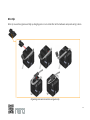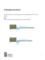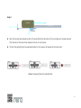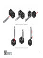
1
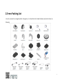
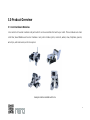
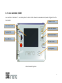
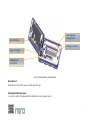
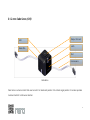
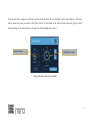
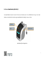
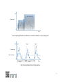
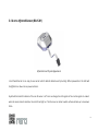
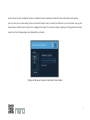
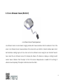
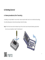
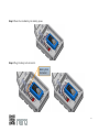
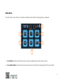
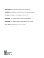
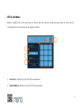
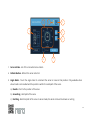
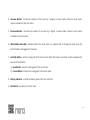
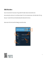
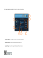
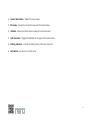
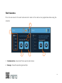
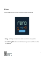
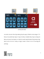
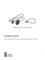
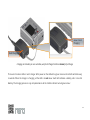
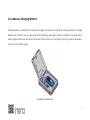
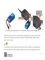
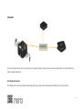
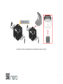
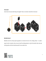
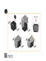
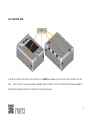
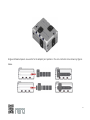
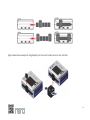
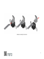
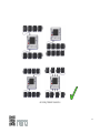
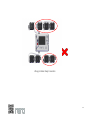
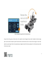
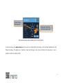
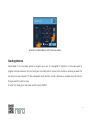
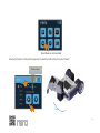
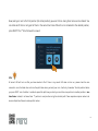
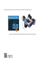
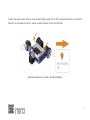
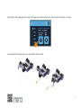
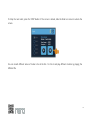
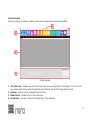
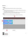
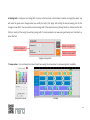
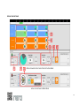
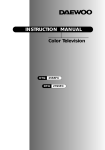
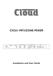
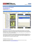
User’s Manual Table of Content Chapter 1.0 Introduction 2.0 rero Packing List 3.0 Product Overview 3.1 rero Hardware Modules 3.1.1 rero controller (GC06) 3.1.2 rero Cube Servo (G15) 3.1.3 rero Head Module 3.1.4 rero IR sensor 3.1.5 rero Ultrasonic Sensor 4.0 Getting Started 4.1 Battery Installation 4.2 rero Controller Menu 4.3 Setting Cube Servo and Sensor IDs 4.4 Charging Battery 4.4.1 Charging on rero Controller 4.4.2 Advance Charging Method 5.0 Build Your Own Robot! 5.1 rero Hardware Construction 5.2 Dismantle rero into Parts 5.3 Wiring 6.0 rero Programming 6.1 Teach Mode Page 1 2 3 3 4 9 11 16 18 19 19 24 42 43 45 47 49 49 60 64 67 67 7.0 8.0 6.2 rero Animator rero Remote Troubleshooting 8.1 rero LED Blink Status 8.2 FAQ 80 95 104 104 106 1.0 Introduction Thank You & Congratulations! What is rero? A reconfigurable robotics Construction kit with flexible slide lock assembly mechanism. rero does not use screw, bolt or nuts for assembly instead it use novel slide lock mechanism which make it so simple and time saving to complete a robot. rero come with loose parts which empower user’s robot building creativity and imagination. rero parts can be combined to build up robots, redesigned, taken apart and put back together in multiple ways. There are no specific assembly rule that limits the user to build up new robots. rero has several programming methods. The most basic way to program a complete rero robot is Teach Mode. User teach rero and rero replay back what it remember from the teaching. With rero animator, user can create time-lined motion sequences similar to making an action movie for rero. Boost Your Creativity and Imagination with rero ! 1 2.0 rero Packing List rero set is packed in an elegant plastic storage box. rero standard set included modules and parts shown as following 2 3.0 Product Overview 3.1 rero Hardware Modules rero consists of several modules and parts which can be assembled to build up a robot. These modules are main controller, Head Module and sensor modules. rero parts includes joints, connects, wheel, claw, footplate, spacers, wire clips, extension wires, and rero opener. Example robot assemblies with rero 3 3.1.1 rero Controller (GC06) rero controller is the brain of rero robot system. It controls all the Cube Servo movement and process all Signals from the rero sensors. USB Micro Port Touch Screen LCD RGB LED Indicator Charging Port Bootloader Button Power Button Thumb Screw Loud Speaker Main Controller Top View 4 Touch Screen LCD Touch screen Graphics User Interface (GUI) to access the main controller standalone functionality. Charging Port Charging connector for rero battery charging. Power Button Turn on and off the main controller unit. Long press for 2 seconds to turn on or off the main controller unit. USB Micro Port USB Micro port is for computer interface. User can load the program from the computer into the main controller through this USB connectivity. RGB LED indicator Status indicator of rero controller Bootloader Button Boot into bootloader mode by press and hold bootloader button while power on by pressing power button. User can update rero controller firmware in bootloader mode. Thumb Screw Access to the battery compartment under the LCD. Loud Speaker Generate touch screen tone, and system sounds. 5 Output Ports Slot Output Ports Slot Latch rero Controller Side View Sliding Slot 6 Sliding slots with latch for assembly with rero parts to create a complete functional robot. Output Ports 6 output slots at two sides or the rero controller for daisy chain servos and sensors. 6 Rechargeable Battery Space MicroSD Card Battery Connector Main connector Main connector Battery Cells Connector rero Controller Battery Compartment MicroSD card MicroSD card is used to save rero files and settings. Rechargeable Battery Space rero comes with rechargeable Lithium Battery as main power source. 7 Battery Connector High Ampere Dean-T connector to supply power for rero Cube servos and sensors. Battery Cells Connector Connector battery cells to main controller. Main Connector Battery and signal wires for rero main circuit board. Always make sure the cable is properly latched to connectors after installing or removing battery. 8 3.1.2 rero Cube Servo (G15) Output Connect LED Latch Male Wire Slot Female wire Cube Servo Cube Servo is a Servo motor that user can set it to rotate and position it to certain angle position. It can also operate in wheel mode for continuous rotation. 9 To test Cube Servo using rero controller, connect the Cube Servo to rero controller. Go to ‘Servo’ Menu. In the Servo menu, select the servo you want to test from the list of connected servo. LED on Cube Servo will light on when selected. Drag on the round meter to change the position angle of the servo. Select a Servo Drag here to test Testing Cube Servo with rero Controller 10 3.1.3 rero Head Module (RR-SH-01) rero Head Module has build in sensor of IR sensor and Sound sensor. It has 2 RGB LEDs as the eyes. rero Head module can be attached to Cube Servo give Head Module the flexibility to move or rotate. IR Sensor Sound Sensor Eyes Head Module Physical Appearance 11 User can test rero Head Module using ‘Sensor’ menu on rero Controller. Connect the Head Module to rero controller then go into Sensor Menu, select the ID of Head Module in the list of sensors. There are 3 features can be tested, namely the sound sensor, IR sensor and RGB LEDs. The sound sensor value and IR sensor value is display as scrolling bar with the value that varies from 0 to 255 depending on the surrounding sound level or the reflected IR rays. There are 3 check boxes to turn on or off the RGB LEDs colours. User can turn on or off single or mutiple color by checking the check boxes. Sensor Menu and Head Module Test. 12 Head IR sensor IR sensor is located infront of the Head Module above the eyes. IR sensor is used for trigger the robot to start when user wave their hand infront the face of robot. Head Sound Sensor (Microphone) Microphone is located inside of the Head Module and it is invisible from outside. Microphone can be used to detect maximum sound volume, trigger robot to start by hand claps. It has features of capturing maximum sound level detection, hand clap counter and current sound volume level. Sound volume is sampled at sampling frequency of 3.9KHz. User can set threshold level for the hand clap detection. Hand clap detection is done at interval of 800 miliseconds. This means that, when a clap has been detected, the sensor will ignore any claps within the 800 miliseconds, sensor will only detect for second clap after 800 miliseconds. This to prevent a single clap being detected as multiple claps. 13 255 Max Sound Level Sound Level 0 Time Audio sampling (dashed line) and Maximum sound level (shaded) on every sampling time 255 Clap 1 Clap 2 Clap 3 Sound Level Clap Threshold 0 >800ms >800ms Time Clap Threshold (dashed line) and Clap detection. 14 Head Eyes (RGB LEDs) By default the eye will light on with white color when powered on. User can set different colour to the eye to give beautiful outlook to the Head Module. Eyes are composed 2 RGB LEDs, the color of the eyes are based on 8 bit RGB true colour set by user. User can utilize the to display different status of their robots too. For advanced user: Internally the eyes are used by Head module to notify user of certain information too. Eyes will blink in red colour for 4 times if user call a reset factory defaults to the Head Module. If user set alarm LED to on, the eyes will blink when there is error packet received (range error, checksum error or instruction error). 15 3.1.4 rero Infrared Sensor (RR-IS-01) Infrared Sensor Physical Appearance rero Infared Sensor is an easy to use sensor which detects obstacle and proximity. When powered on the LED will be lighted on in blue color as power indicator. By default the Red LED indicator of the rero IR sensor is off. User can change the LED register of the control register to make it when the sensor detects obstacle, the red LED will light on. The IR sensor can detect a white surface obstacle up to maximum 30cm. 16 rero IR sensor has auto calibration function to calibrate the sensor detection threshold to the surface that it will operate. User can test rero IR sensor using the rero Controller ‘Sensors’ menu. Connect the IR Sensor to rero Controller, then go into Sensor Menu. Select the rero IR sensor ID to display the IR values. The IR sensor values is display as scrolling bar with numeric value from 0 to 255 depending on the reflected IR ray intensity. Testing rero IR sensor using rero Controller ‘Sensors’ Menu 17 3.1.5 rero Ultrasonic Sensor (RR-US-01) rero Ultrasonic Sensor Physical Appearance rero Ultrasonic Sensor is and ultrasonic ranging module which measure distance from the obstacle in front of the sensor. rero Ultrasonic Sensor measure distance from at least 5cm up to 200cm. It detects obstacle down to 0cm but the distance reading may be not true. User can test rero Ultrasonic sensor using the rero Controller ‘Sensors’ menu. Select the rero Ultrasonic sensor ID to display the distance. The distance is display as scrolling bar with numeric value of distance from the object in front of the sensor. Adequate area is needed for the echoing of ultrasonic sound especially if the object is at distance more than 30cm . 18 4.0 Getting Started 4.1 Battery Installation (First Time Only) rero battery is not preinstalled in rero controller. User will need to install it into the rero controller before starting the robot building process. Follow the steps below to install the battery. Step 1: Turn thumb screw counter clockwise to open the controller cover and reveal the battery compartment. User can use a screw driver to help if its hard by hand. 19 Step 2: Plug in the Dean-T connector of battery and let the wires run under the wire guide. Plug In Dean-T Connector Wire Guide 20 Step 3: Place the rero Battery into battery space. Step 4: Plug in battery cells connector. Battery Cells Connector 21 Step 4: Close the cover and lock back the controller cover by turning the thumb screw clockwise 22 Step 5: Power on rero controller by pressing the Power Button to verify that battery is properly installed. rero Controller will display the Main Menu after Boot Screen. Rero controller Main Menu 23 4.2 rero Controller Menu rero controller has embedded operating system (OS) and the firmware can be updated online through the USB bootloader. rero controller has multiple menus that serve different functions to user. Boot Page When the rero controller is turned on, the rero logo is shown to indicate the system is booting up. 24 Main Menu This is the main menu of the rero controller and will be shown after the booting process completed. 7 2 8 1 3 4 6 5 1. Set ID Button - Enter the set ID sub-menu to read or modify the servo motor and sensor ID. 2. Servo Motor Button - Enter the servo motor sub-menu to test and set the working path of the servo motor. 25 3. Sensor Button - Enter the sensor sub-menu to test the sensor and head module. 4. Teach Button - Enter the teach sub-menu to teach the motion of the robot with teach mode. 5. Play Button - Enter the play sub-menu to playback the motion of the robot. 6. Remote Button - Enter the remote sub-menu to control the robot via rero Remote. 7. Settings Button - Enter the settings sub-menu to change the settings of the rero controller. 8. Battery Indicator - Indicate the battery level of the rero controller. 26 SET ID Sub-Menu Read or modify the ID of the servo motor or sensor with this sub-menu. Only one servo motor or sensor can be connected to the rero controller while using this function. 3 5 6 1 2 4 1. Current ID - Shows the current ID of the servo/sensor. 2. Read ID Button - Read the current ID of the servo/sensor. 27 3. Numeric Keypad - Key in the new ID of the servo/sensor. 4. New ID - Shows the new ID keyed in with the numeric keypad. 5. Battery Indicator - Indicate the battery level of the rero controller. 6. Exit Button - Go back to the main menu SERVO Sub-Menu Test the movement of the servo motor, change the servo motor to wheel mode or position mode, as well as set the path limit of the servo motor in this sub-menu. Upon entering this sub-menu, rero controller will search for all the connected servo motor and this will take up to 1 second. All the servo motors will be listed under the servo list box. Select a servo motor from the list and the following screen will be shown. 28 3 8 9 1 4 5 2 6 7 1. Servo List Box - List of the connected servo motors. 2. Refresh Button - Refresh the servo motor list. 3. Angle Meter - Touch the angle meter to command the servo to move to that position. Only available when wheel mode is not enabled and the position is within the valid path of the servo. a) Needle - Point to the position of the servo. b) Green Ring - Valid path of the servo. c) Red Ring - Restricted path of the servo. In wheel mode, the whole circle will be shown as red ring. 29 4. Increase Button - Increase the position of the servo by 1 degree. In wheel mode, rotate the servo motor counter clockwise or stop the motor. 5. Decrease Button - Decrease the position of the servo by 1 degree. In wheel mode, rotate the servo motor clockwise or stop the motor. 6. Wheel Mode Check Box - Indicate whether the servo motor is in wheel mode. To change the mode, press the Set Path button and toggle this check box. 7. Set Path Button - Set the moving path of the servo motor. When this button is pressed, it will be replaced with Save and Cancel button. a) Save Button - Save the moving path of the servo motor. b) Cancel Button - Discard the moving path of the servo motor. 8. Battery Indicator - Indicate the battery level of the rero controller. 9. Exit Button - Go back to the main menu 30 SENSOR Sub-Menu Sensor can be tested in this sub-menu. The eyes LED of the head module can be tested here too. Upon entering this sub-menu, rero controller will search for all the connected sensor and head module. This may take up to 1 second. All the sensors/head module will be listed under the list box. Select a sensor from the list and the following screen will be shown. 8 9 3 1 2 4 31 If the head module is selected, the following screen will be shown. 8 9 3 1 2 5 6 7 1. Sensor List Box - List of the connected sensors/head module. 2. Refresh Button - Refresh the sensor/head module list. 3. Sensor Type - Shows the type of the sensor/head module. 32 4. Sensor Value Slider - Shows the sensor value. 5. Mic Value - Shows the microphone value of the head module. 6. IR Value - Shows the infrared sensor value of the head module. 7. LED Check Box - Toggle the RGB LED on the eyes of the head module. 8. Battery Indicator - Indicate the battery level of the rero controller. 9. Exit Button - Go back to the main menu 33 TEACH Sub-Menu This is the sub-menu for the teach mode where the motion of the robot can be programmed without using the computer. 8 7 1 2 3 4 6 5 1. File Radio Button - Select which file to save the robot motion. 2. Message - Shows the operation guide and tips. 34 3. Time Frame - Shows the number of recorded time frame. 4. Teach Button - Press to start teaching and this button will be changed to Next button. 5. Next Button - Press to add the current position of the servo motors to the motion. 6. Stop Button - Press to stop teaching. 7. Battery Indicator - Indicate the battery level of the rero controller. 8. Exit Button - Go back to the main menu. 35 PLAY Sub-Menu Sub-menu to playback the programmed motion. 9 1 8 2 3 4 5 6 7 1. File Radio Button - Select which file to play. 2. Message - Shows the operation guide and tips. 3. File Type and Name - Shows type and name for the selected file. 36 4. Time Frame - Shows the currently playing time frame. 5. Time - Shows the playing time in second. 6. Play Button - Press to start playing the selected file. 7. Stop Button - Press to stop playing. 8. Battery Indicator - Indicate the battery level of the rero controller. 9. Exit Button - Go back to the main menu. 37 REMOTE Sub-Menu Enter this sub-menu to control the robot with the rero Remote Apps in your smart phone. The name of the robot will be shown on the title bar and it can be changed by using the rero Animator. 1 2 3 1. Robot Name - Name of this robot. 2. Battery Indicator - Indicate the battery level of the rero controller. 3. Exit Button - Go back to the main menu. 38 SETTINGS Sub-Menu Set the screen brightness and volume here. 6 1 3 7 2 4 5 1. Brightness Button - Reset the LCD brightness to the default level. 2. Brightness Slider - Set the LCD brightness. 3. Volume Button - Reset the system volume to the default level. 4. Volume Slider - Set the system volume. 39 5. Firmware Version - Shows the controller firmware date and time. 6. Battery Indicator - Indicate the battery level of the rero controller. 7. Exit Button - Go back to the main menu Lock Screen rero controller will lock the screen and enter standby mode when the screen is not touched for more than 2 minutes. To wake it up again, simply touch the screen and unlock it by sliding the slider bar to the right. 1 1. Unlock Slider - Slide from left to right to unlock the screen. 40 USB Screen This screen is shown when the rero controller is connected to the computer via the USB cable. 2 1 1. USB Logo - The USB logo is shown when the rero controller is connected to the computer via USB. 2. Turn On USB Storage Button - Press to enable the USB mass storage device to access the files in the SD card from the computer. 41 4.3 Setting Cube Servo and Sensor IDs Every Cube Servo and Sensor has its own ID. Cube Servo and sensor are preset with ID, however user can still change the ID to a preferred number and re-label it with the sticker provided. User will need to make sure that all the Cube Servo or Sensors connected to a rero controller must has different ID, else communication error will occurred and rero controller will not be able to detect the connected Cube Servos Sensor. To change the ID, user must connect only one Cube Servo or only one sensor to rero controller. Go into SET ID menu of rero controller and key in the ID that you want to set and press ‘OK’ button to set the ID. User can press ‘Read ID’ button to get the current ID of servo or sensor. Remember to change the ID sticker and label it with correct ID after changing the ID. There are spare stickers provided for this purpose which comes together with rero robotics kit. Set ID menu 42 Info Cube Servo and sensors can have ID as from 0 to 253. Remember to label the servo on ID sticker once you done setting ID of servo or sensor. 4.4 Charging Battery rero battery level is always monitored by rero controller and is display by the battery icon at right upper corner. The battery level is indicated by shaded level in the icon and also the colour of the icon. The battery icon colour will change from green to yellow and red when low battery. rero controller will display a empty battery screen when the battery voltage is too low. It will shutdown in 6 seconds after the empty battery screen is shown. User can charge the battery any time to keep the battery full. 43 Full Battery Critical Battery Empty Battery rero battery status indicator rero controller comes with Lithium Polymer Battery (LiPo) with capacity of 1300mAh at nominal voltage of 11.1V. Please use the provided battery charger to charge rero’s battery. Incompatible battery charger can damage the battery or even cause fire and explosion. rero robotics kit come with quality LiPo Balance Charger. Balance charger makes sure that all the cells in battery are charged in balance to reduce the risk of cell overcharge and undercharge . 44 rero’s charger (AC input 100V -240V, 50/60Hz) and charging cable 4.4.1 Charging on rero Controller Connect the Charger to the rero controller with the charging cable provided as shown by picture following. 45 Green: Finish Charging Red: Charging Charging rero’s battery in rero controller, wait for all Charger’s LED turn Green for full charge. There are 3 bicolour LED on rero’s charger. After power on the LED will be green colour and red LED will blink every 2 seconds. When the charger is charging, all the LED is in red colour. Each LED indicates a battery cell in rero LiPo Battery. The charging process is only completed when all the 3 LEDs indicator turned green colour. 46 4.4.2 Advance Charging Method Adult supervision is needed for this method of charging. This method is to charge rero battery directly from charger without rero controller. User can get access to the battery by opening the battery compartment. To get access to battery compartment, user will need to unlock the thumb screw on rero controller by turning it counter clockwise to open the rero controller casing. rero Battery Compartment 47 Green: Finish Charging Red: Charging rero’s battery, standalone charging without rero conteroller, battery is full only if all the LEDs turn Green Color Battery can be taken out from the rero controller after disconnecting the battery cells connector and Dean-T power connector. Connect the battery cells connector to the charger to charge the battery. Wait for all LEDs change to green color for a full charge. Info Do not attempt to short any of the battery terminals which can cause fire or explosion. For a prolonged storage of rero controller, user is advice to keep the battery capacity at around 60 percent only for a greater battery life time. 48 5.0 Build Your Own Robot! 5.1 rero Hardware Construction Joints Joints Most of the part has Joint as shown in figure. These Joints will be attached to connects to create robot assembly. 49 Connects Connects Some rero parts have Connect as shown in the figure above. These connects can be attached to rero parts that has Joint to build robot part. G15 Output Connect G15 Output Connect has direction marking which user will need to follow when sliding it into the joint slot. 50 Direction Mark Follow the direction marking when connecting Cube Servo to joints 51 Interconnect Interconnect can be use to attach two joints together. There is no direction constraint for interconnect. Rotatable Connect Rotatable connect has similar physical appearance as interconnect but has 2 free rotating surfaces . It is used to support U-Joints connection and can be use to build free rotating wheels too. U-Joint Connected to Cube Servo are normally used as robot’s Arms and Knees which has one rotation axis. 52 53 Wide U-Joint can be use to build a compact 2 axes rotating Joint which can be use at shoulder and ankle of robot. 54 55 rero Controller Slots Slots In Order to connect rero parts to rero controller, user MUST use Adapter Joint to convert rero controller slot into Joint. Then rero part can be connected to Adaptor Joint to attach it to rero controller. Recommended Adapter Joints direction facing on each rero Controller slot is as shown below. 56 Single and Double Spacers are used to fix the Adaptor Joint position in the rero controller slot as shown by figures below. 57 Figure below shows example of using Adaptor Joint to connect a Cube Servo to rero controller. 58 Wire Clip Wire clip is used to organize and tidy up dangling wire on rero robot after all the hardware setup and wiring is done. Organizing wires and connectors using wire clip 59 5.2 Dismantle rero Into Parts To dismantle rero parts, the basic step that apply for all parts that locked together by the latch is shown as following: Step 1: Push the rero opener into the slot to push down the latch to release the locked part. rero Part rero Opener Slot Latcher rero Part rero Opener Slot Latcher 60 Step 2: rero Part rero Opener Slot Latcher Push the Connect part locked by latch in the Joint/Slot to the direction of the rero Opener to release the part from the slot, at the same time release the force on rero Opener. Or Push the part with Joint to opposite direction of rero opener to release the Connect parts. Release rero spacer from rero controller slot. 61 Release rero Cube joint from Interconnect Release rero Interconnect from Cube Joint slot 62 Release rero claw from Cube Servo 63 5.3 Wiring Daisy Chained Cube Servo and Sensor In Daisy Chain connection, multiple Cube Servo or sensors are wired together in sequence or in a ring. Power and communication signal are transferred from one servo or sensor to another on the single serially connected line. Hence, not all the Cube Servos or sensors need to be connected directly to rero controller’s output ports, instead it can be connected to other Cube Servos or sensor to get power and communication line. This can save a lot of direct connections from controller to servos and sensors and make the whole wiring simple and neater. Connection to rero controller, connection between cube servo or sensors 64 rero Daisy Chained Connection 65 Wrong or Broken Daisy Connection 66 6.0 rero Programming 6.1 Teach Mode Set Path Limit This is an important step the make sure all the Cube Servo will only move in a safe path that does not clash on other rero parts after it is assembled as a robot. To Set Path Limit go into Servo Menu. Every servo will need to set it path. Select a servo from the Servo list displayed based on its ID. The selected Cube Servo will turn on its LED when selected. 67 Select a Servo from the Servo list Press Set Path to start setting the path limit for the selected servo. Rotate the selected Cube Servo, together with the attached part in both movable directions to the maximum. This is to let the rero controller knows how much angle that servo can move. 68 Set the Allowable moving Path for the Selected Servo You will notice the green and red sector on the position meter changed. Green sector indicates the safe moving path, and red sector shows the path that will clash and Cube Servo will not move into that region. Press ‘Save’ button to save the path limit to the selected servo. Repeat the Set Path Limit procedure for all the Cube Servos that form the rero robot. 69 Green Colour: Moving path Red Color: Path that Cube Servo will avoid Path Limit shown by Green and Red Color on Position Meter To set Cube Servo into wheel mode which the servo can rotate 360° continously, in the Set Path Sub-Menu tick the ‘Wheel’ checkbox. The whole arc of position meter will change to red colour indicates the Cube Servo is not in position mode but in wheel mode. 70 Set Servo into Wheel Mode for 360° continous rotation Teaching Motions Teach Mode is the most basic option to program your rero. It is designed for beginner or those who wish to program a simple movement for rero. Twist your rero robot joints or servos to the position or posture you want it to be, then press save. Repeat it for the subsequent robot positions so that it becomes a complete series of motions that you want the robot to move. To enter this mode, go to main menu and then press ‘TEACH’. 71 Teach Mode on rero Controller Select any file (File 1 to File 5) that you want to save the motion file. then press ‘Teach’. Time Frame Twist 72 Now, twist your rero to the first position (the initial position) you want it to be. Every Cube Servo can be rotated. You can rotate all of them or only part of them in the same time Frame. When the rero is twisted to the desired position, press ‘NEXT’. The 1st time frame will be saved. Info All servos’ LED will turn on after you have selected a file. If there is any servo’s LED does not turn on, please check the wire connection. rero Controller does not care the path taken when you twist your rero. It will only ‘remember’ the last position before you press ‘NEXT’. rero Controller is unable to repeat the path how you twist your rero from one position to another position in one time frame. Instead, it will move from 1st position to next position using the shortest path. Please separate complex motion into more multiple time frames to make perfect motion. 73 Repeat the same process for the second desired position and the subsequent positions. Twist Twist robot to desired position then press NEXT to record all servos’ position into time line 74 To teach the wheel mode’s servo to move forward, slightly rotate (10° to 90°) the wheel Cube Servo in the desired direction. Do not rotate more than 1 rotation to avoid confusion to the rero Controller. Teach wheel mode Servo to rotate in the desired direction 75 Press ‘stop’ when you have done and then ‘X’ to go back to the main menu. Info You can teach up to 65535 positions or time frames in 1 file. Each time frame positions will take 1 second to complete. 76 Playing Motions To Play the motion file that has been saved from the teach motion step. Go into ‘PLAY’ Menu Select the file that you save the motions. 77 Press ‘Play’ to start playing all the motions that was save. Observe the running ‘Time Frame’ and Time’ on screen. rero robot will start moving once you pressed the ‘PLAY’ button. 78 To Stop the rero robot, press the ‘STOP’ Button. If the screen is locked, slide the Slider on screen to unlock the screen. You can record different series of motion into all the File 1 to File 5 and play different motions by playing the different file. 79 6.2 rero Animator Minimum System Requirements for rero Animator Software Prerequisites: - Microsoft Dot Net Framework 4.5 Operating System: - Microsoft Windows XP, Windows Vista, Windows 7 and Windows 8 (32/64 bit) with the latest updates. System Requirements: -Processor: 1.5GHz or faster -RAM: 1GB or more Software Installation Download rero Animator software from rero website’s download page (http://rero.com.my/downloads). Double click on the downloaded file to initiate software installation. Follow the simple installation steps. A short-cut will be created on your desktop. Double click on it to launch rero Animator software. rero Animator icon 80 Interface Overview Every time you open rero Animator software, you will see the programming interface as shown below. 1 2 3 4 Interface Overview 1. 2. 3. 4. Title & File name -- Software name and current motion file name are displayed here. Shows [new] if the current motion has not been saved. Asterisk symbol (*) behind the motion file name indicates that changes has been made. Menu bar -- Find basic tool for working with motion file here. Motion Canvas -- Create & edit your robot motion here. Control Panel -- Tune Servo1 and Action1’s settings here. (1 To be explained.) 81 Menu Bar The Menu Bar consists of large buttons with thumbnail image. 1 2 3 4 5 6 Menu bar 1. Motion File New Motion file -- Create new motion file & automatically detect Servo(s) available if rero Controller is connected & powered up. Open Motion file -- You can browse saved or downloaded Motion file via the file browser window. Save Motion file -- Saves current Motion with desired file name. Idea! You will see this rero Motion file icon appears as the saved file if your system supports this feature. 82 2. Robot Connection Connected Not connected Robot connection status -- Shows USB icon with tick symbol (√) when rero Controller is connected and powered up, otherwise shows icon with cross symbol (×). Robot Name -- Read & edit robot name saved in rero Controller. This name will appear in rero Remote. Upload Motion -- Uploads the motion to rero Controller. Download Motion -- Downloads the motion from rero Controller. 3. Add Servo & Action Add Servo -- Create new Action behind the last column. 83 Add Action -- Create new Servo below the last row. 4. Editing Copy Action -- Copies the selected Action. Current version only supports one Action copy. Cut Action -- Cuts the selected Action. Current version only supports one Action cut. Paste Action -- Paste the copied/cut Action to the selected location. 5. Refresh Refreshes current Motion. 84 6. Information Displays information like software name, software version, company and rero website link. -- Always make sure your copy of software is up-to-date by checking on rero website download page and this information message box. Software version (build date) Information message box If you are not sure about the function of a button, mouse over the button shows tips (button name and keyboard short-cut key if available). Mouse arrow Idea! Tips Mouse over tips 85 Motion Canvas 1. Time frame -- This column indicates the starting time and duration of an Action, at the resolution of 0.2 sec/frame. 2. Servo -- It shows the ID number and name (comment) of a servo motor and enables you to configure each servo motor. A Servo can be configured to Position mode or Wheel mode. -- Servo in Position mode will move to the desired position (angle in degree) and stay there until next position is updated. -- Servo in Wheel mode can rotate 360 degree clockwise or counter clockwise continuously. 3. Action -- gives you the control over servo motor’s position, speed, LED & etc., at different time frame and duration. 1 2 3 Motion Canvas 86 Servo Control Panel 1 2 3 4 5 6 7 Servo Control Panel in Position mode, without rero Controller connected. 1. Selected Servo -- Click on the Servo ID column to select a servo. 2. Robot Connection Status -- USB symbol with ‘X’ sign shows rero Controller is not powered up and/or not connected to computer. You will see USB symbol with ‘√’ sign when rero Controller is detected. rero Controller is disconnected rero Controller is connected 87 3. Servo ID -- Servo ID can be edited by click on ‘Edit’ button. Valid ID range is between 0 to 253. It’s recommended NOT to edit the pre-set Servo ID to prevent having two Servo motors with the same ID in your rero system. Press ‘Save’ Edit Servo ID Editing Servo ID 4. Servo Name -- You can give a name to the selected servo motor to improve the readability of your program. 5. Servo Mode & Diagram -- Configures the selected Servo to Position mode or Wheel mode. The diagram shows the moving path in when Servo is in Position mode or wheel image in Wheel mode. Moving path Position mode selected Restricted zone Position mode Wheel Wheel mode selected Wheel mode 88 6. Moving Path -- Configures the moving path of a Servo in Position mode. Use the slider or buttons to change the values. You will notice the green sector changes when you modify the limits. Click ‘Apply’ after setting the desired moving path for the changes to take effect. You can read the current moving path of the selected Servo by clicking ‘Read’ too. Please note that this facility is mainly for fine-tuning the existing moving path. It’s recommended to set new moving path using rero Controller’s on board function. Read moving path Edit moving path Apply moving path Configure Moving Path 7. Group colour -- You can change the colour of each Servo using the colour picker to improve program’s readability. Group Colour picker Example 89 Action Control Panel 1 2 5 8 3 4 6 7 Motion Canvas & Action Control Panel in Position Mode Action Control Panel in Wheel Mode 90 1. Actions in Position mode -- select one of the Actions to edit it. 2. Actions in Wheel mode -- select one of the Actions to edit it. 3. Moving Angle -- This appears when an Action in Position mode is selected. It sets the Action’s destination in degree. You can edit the value in Destination box or directly click on the pie diagram to set the destination. When rero Controller and the servo with correct ID are connected, the servo will move simultaneously. Destination (End position of the Action) Start position of the selected Action = Destination of previous Action. Left click & drag on the moving path to change destination Edit Moving Angle Sweep = Destination - Start 4. Wheel Direction & Speed -- This appears when an Action in Wheel mode is selected. You may use it to change Servo’s direction and speed at that time frame. Click on ‘Test Run’ to test the direction and speed. Left click on the diagram to change direction Change speed Test Run / Stop button Change direction Edit Wheel Direction & Speed 91 5. Moving Time -- Edit moving time of the selected Action here. Action starts to move at this time frame Duration - Action will move for this period of time Action stops to move at this time frame Edit Moving Time End Time = Start Time + Duration 6. Light -- Toggle on/off the servo motor’s LED for the period of time. You can control the each servo motor’s LED to blink at different pace. 7. Torque -- Toggle on/off the torque of the servo motor for the period of time. When it’s ON, the servo motor will move to the desired destination or rotate in the direction at the speed you set earlier. When the torque is OFF, the servo motor will not move for that period of time regardless of the destination, direction and speed’s settings. 8. Servo ID & Name -- This section is disabled in Action Control Panel. However, you can always edit the Servo ID and name in Servo Control Panel. Idea! Always connect rero Controller to your computer while using rero Animator to enjoy better experience while programming your robot’s motions. 92 Upload Motion After you have created your robot motion. A click on Upload button in Menu Bar will prompt you to save your Motion file (if you haven’t do so) and the Upload Motion message box appears. 1 rero Remote (Android App) 2 3 Upload Motion to rero Controller message box rero Controller (Play) 1 & 2. Select Upload Location -- Select the upload location based on where you want to play the Motion file. If you have an Android smartphone or tablet, you can download the free rero Remote App from Google Play. 93 3. Loop -- Select if you want to play the Motion file repeatedly when you press and hold the button on rero Remote (or click Play on rero Controller). You can stop the Motion by releasing the button on rero Remote (or click Stop on rero Controller). Download Motion There are cases where you wish to read the Motion file stored in rero Controller into rero Animator software. For instance, you have created a Motion using Teach Mode in rero Controller. Now you want to save this Motion to your computer and at the same time improve the the Motion using rero Animator software. You can do that with Download Motion. From the Download Motion message box, select the location of the Motion file in rero Controller. The valid rero Motion file will be transferred to rero Animator after clicking ‘OK’ button. Servo(s) and Action(s) in the Motion file will be displayed according to their time frame in Motion Canvas. Select the location of the Motion file in rero Controller Download Motion from rero Controller 94 7.0 rero Remote Installation of rero Remote App rero Remote App Icon To install rero Remote app, user can connect to internet and install it from Google Play Store (https://play.google.com/store/apps). Search for ‘rero’ keyword to find rero Remote. Click install to install rero Remote app to the phone. 95 rero remote Bluetooth Connection Battery Status Bluetooth Status rero Remote main screen 96 rero Remote request for Bluetooth to be turned on. rero Remote will request user to turn on Bluetooth of the phone. Touch Allow to turn on bluetooth of phone 97 If rero remote app had previously connected to a rero controller, it will automatically search for the same rero controller to create bluetooth connection. Press Bluetooth Status to search rero Controller rero Remote Searching for previously connected rero controller You can press the back button of your phone to cancel searching previous rero if you do not want to connect to it. Press the bluetooth status icon to search for new rero controller that you want to connect. 98 Bluetooth Connection Status: Searching, Connected, Disconnected Refresh button to search again Bluetooth Devices around again if first search failed Select ‘rero’ to connect 99 Select the rero controller, to connect. The bluetooth address of every rero controller is different. You can check the bluetooth address of your rero controller from the Bluetooth Menu of rero controller. When rero Remote is connected to rero controller, the bluetooth icon will change to show connected status, and battery icon will shows the battery level of rero controller. Battery Level Bluetooth Connected rero Remote Connected to rero controller 100 On rero Controller, user will need to go in the Remote Sub-Menu in order to enable bluetooth communication and control from rero Remote. Remote Sub-Menu on rero Controller 101 rero Remote Control Buttons Cross Buttons, Circle Buttons, Rectangle Buttons User use these rero Remote control buttons to run rero program that is assigned to the buttons. In order to play file by using rero remote, rero controller must be in ‘REMOTE’ menu. By default the 5 files saved in teach mode is assigned to the 5 Rectangle Buttons. 5 motion files by the teach mode can be directly played from rero Remote using the rectangle buttons. For Cross buttons and Circle buttons, user can assign files to it using rero Animator software. 102 Exit rero Remote Swipe from edge Status bar Navigation bar Swipe from edge Back Button Swipe from edge of screen to reveal back phone navigation bar and status bar rero remote will apply immersive full screen for Android version KitKat (Android 4.4, API Level 19) and above. To exit the full screen, user will need to swipe from the screen edge to reveal the back button if the phone used has on screen navigation bar. Press the back button to exit rero Remote. Remember to turn off the bluetooth of the phone after exiting rero Remote if not using it for other app. 103 8.0 Troubleshooting 8.1 rero LED Blink Status rero controller rero RGB LED will turn on or blink on several conditions as shown in table below: LED System State/Error White LED blinks (1Hz) Insuffiecient memory to start RTOS White LED blinks (10Hz) RTOS stack overflow Red LED turns on System is shutting down Red LED blinks 2 times Malloc error Red LED blink 2 times RTOS stack is low Yellow LED blinks Accessing microSD card Blue LED turns on Bluetooth is connected Blue LED blinks Bluetooth data transmitted/received Green LED blinks System standby LED off ready 104 Cube Servo and Sensor Cube servo and rero’s sensor red LED will blink on several condition as shown below. Error Description Instruction Error Communication error (wrong instruction) Overload Error Cube servo unable to move for more than 8 seconds Checksum Error Communication error (Data Check error) Range Error Communication error (Data received invalid) Overheating Error Cube Servo overheat shutdown Angle Limit Error Cube Servo goal position is out of allowed moving path Input Voltage Error Input voltage is out of correct voltage range For Cube Servo Overload Error condition, user will need to turn off the servo by removing the power to the servo or turn off rero controller to cut off the power in order to reset the cube servo to normal condition. For Cube Servo Overheat Error condition, user will need to turn off servo and wait for the servo to cool down. 105 8.2 FAQ 1. No Cube Servo (G15 Detected)! Answer: Check Cube Servo Wire Connection. Unplug all Cube Servo and sensor, plug only one G15 to rero controller and try again. Check if there is 2 servos with same ID. Check if the Cube Servo’s LED blink once when the rero controller is power on. If no, check if rero Battery Dean-T power connector is properly connected. 2. Computer does not detect rero Storage. Answer: Check USB cable connection. Check if pressed Turn on Storage on rero controller touch screen. 106