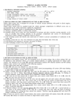
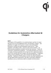
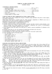
1
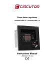
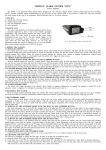
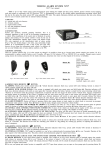
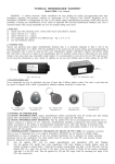
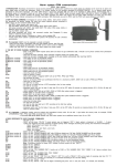
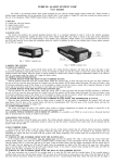
VEHICLE ALARM SYSTEM 'GN7'
Installation manual
1. THE SET.
a) system unit with connecting wires;
b) 2 remote controls;
c) engine bonnet switch;
d) user and installation manual;
e) siren (optional).
2. TECHNICAL SPECIFICATIONS:
P operating temperature ………………………………..…..............
P rated supply voltage ……………………………………..............
P average current consumption without inbuilt sensor .................
P average current consumption with inbuilt sensor ......................
P siren drive current …………......…………...................................
P cut - off circuit current ..................................................................
P average distance of remote control ………......…...……............
– 40° C to +85° C;
9 - 15 V DC;
£ 14 mA (U=12V);
£ 20 mA (U=12V);
£ 2 A;
£ 25 A;
5 - 10 m.
3. INSTALLATION OF THE ALARM SYSTEM.
Vehicle alarm system 'GN7' is designed for all types of vehicles (except cabriolets) with petrol or diesel engines, and
12V batteries with negative pole connected to ”ground” (vehicle body).
Vehicle alarm system must be installed inside the vehicle passenger compartment in difficult to access area in accordance
with manufacturer's supplied wiring directions.
Manufacturer of the alarm system recommends:
a) select a qualified installer of vehicle alarm systems;
b) mount system unit in place free from penetration of moisture and other corrosion - causing materials, as far as possible
from heating elements in the passenger compartment and sources of electromagnetic interference (vehicle computer,
fans, blocks of relays);
c) avoid mounting system unit directly onto metal parts of vehicle to prevent accumulation of condensate in the system
unit;
d) mount system unit in a way, wire connectors are going from the bottom side of the unit;
e) avoid placing wires next to moving or hot parts of vehicle;
f) avoid overload of alarm system circuits:
£ 25 A
P cut - off circuit current 1 ............................................................
7
unlock
pulse
current
………….................................................
£ 0,13 A
P
6
lock
pulse
current
.....……………............................................
£
0,13 A
P
4
……………………….........
£ 0,13 A
P cut - off / optional output current
£ 2A
P siren drive current 1 ………………………................................
£ 7A
P right direction indicator control current 5 ….............................
2
left
direction
indicator
control
current
...................................
£
7A
P
4. ALARM SYSTEM SET UP.
'GN7' features up to 82 system settings. Due to these settings 'GN7' can be adjusted to some particular vehicle or
relevant customer requirements. 'GN7' features are set using PIN (personal identification number), FN (feature number)
and SN (setting number) codes. Actions to be performed in the following sequence:
a) open vehicle doors and leave it opened (there is no need to open doors on entering PIN code by alternative way –
see user manual 7.3);
b) enter PIN code (see user manual 7.2 or 7.3), close the doors;
c) wait for approximately 12 seconds (intended for remote control learning), till system LED stops emitting triple flashes
and starts flashing frequently;
d) within 8 minutes after the PIN code entry, in the same way as PIN, enter the FN number of the feature you want to
set. Short flash of direction indicators indicates correct FN entry. No flash of direction indicators, means either
incorrect FN entry or assigned 8 minutes elapsed;
e) if FN code has not been entered due to elapsed time, press
button, enter PIN code, wait 12 seconds and enter FN
once again;
f) if FN code has not been entered due an error, turn off the ignition, wait until system LED starts flashing frequently
and re-enter the FN code. After correct entry of the FN code, the system extends control time for 8 minutes awaiting
a remote control button
press. Within this control time check current SN settings or enter a new one. The system
extends control time to 8 minutes again. This control time is extending every time after checking or entering SN;
g) check SN setting only with the ignition OFF by pressing remote control button
once and counting short flashes of
direction indicators, which equal to SN value;
h) if SN is incorrect, to change it: turn the ignition ON, press button
with 1 second intervals as many times as the
required number of SN. Wait for 3 seconds till short siren beep and flash of direction indicators. New setting has been
entered into memory therefore turn the ignition OFF and check SN setting as described in article 4g.
5. SUMMARY OF ALARM SYSTEM SETTING SEQUENCE.
CONDITION
ACTION
CONTROL
TIME
REMOTE
CONTROL
DIRRECTION
INDICATORS
SIREN
SYSTEM LED
Doors is opened / -
PIN ENTRY
–
–
–
–
Double flashes /
long flashes
REMOTE
CONTROL
LEARNING
12 seconds, is extended
to 12 seconds after
each remote control
learning
Press simultaneously:
PIN is entered
–
–
Triple flashes,
1 second flash after
remote control
is learned
12 seconds after
PIN entry or
remote control
learning
FN ENTRY
8 minutes
–
Indicates
correct
FN entry
–
Double flashes
FN is entered,
ignition OFF
SN CHECK
8 minutes
Short press
of
Indicates SN
value
–
Frequent flashes
FN is checked,
ignition ON
SN CHANGE
8 minutes
Indicates SN
change after
3 seconds
Double flashes
SN is checked
or entered
NEXT FN
ENTRY
8 minutes
–
Indicates SN
change after
3 seconds
Indicates
correct
FN entry
–
Double flashes
Following FN
is entered,
ignition ON
SN CHANGE
8 minutes
Short press
of
Indicates SN
change after
3 seconds
Indicates SN
change after
3 seconds
Double flashes
8 minutes / –
– / short press
of
Indicates correct
FN entry / -
–
Double flashes
/–
END of FN
settings
FN=11 ENTRY or
by remote control
+
+
or
+
Short press of
6. NOTIFICATION ABOUT OPEN SYSTEM INPUTS, DATA ABOUT LAST TRIGGERS.
If system was triggered in armed state, direction indicators will flash four times when disarming the system. 'GN7’
stores the data about last three triggers. This feature enables to ascertain the causes of the false alarm. There are two
ways to do that:
1. Disarm alarm system, turn the ignition ON and count the LED flashes (last trigger indication).
2. Or set FN=71, 72 or 73, press button
and count flashes of direction indicators while ignition is OFF.
Meaning of system LED / direction indicators flashes:
1 flash – sensor (sensors) have been triggered;
2 flashes – doors have been opened;
3 flashes – bonnet has been opened;
4 flashes – trunk / luggage compartment has been opened;
5 flashes – attempts to start (ignition key / hot wire).
7. CERTIFICATE OF INSTALLATION .
I, undersigned qualified installer
(Name, Surname)
certify that installation of
the below described vehicle alarm system has been carried out by myself pursuant to installation manual supplied by the manufacturer of the system.
Vehicle description:
Manufacturer and model:
Serial number:
Registration number:
Description of vehicle alarm system:
Type: 'GN7'. Model:
Official approval number: 97RA-0104829
Installation date:
Installing company:
SEAL
Installer:
(Position, signature)
After installation of the alarm system installer must fill in CERTIFICATE OF INSTALLATION! It is recommended to mark
selected settings in the TABLE OF ALARM SYSTEM SETTINGS (underline SN).
8. SUMMARY OF ALARM SYSTEM SETTINGS.
8.1. MARKED FIELD MEANS:
EU
– the setting complies with requirements of EU Directives. Selection of settings not complying with EU requirements
is permissible if vehicle is operated in non EU state;
GN7_C – the setting is in appropriate software version;
– factory setting;
– pre-programmed setting if differs from factory setting.
GN7_L
GN7_A
EU
FEATURE
GN7_C
8.2. TABLE OF ALARM SYSTEM SETTINGS.
FN=11 Feature: END OF FN SETTINGS.
FN=15 Feature: ALARM SYSTEM CONTROL USING 'GSW1'.
SN=1 Alarm system control using 'GSW1' is OFF.
Alarm system control using 'GSW1' is ON. After learning first remote control the system automatically learns the connected 'GSW1' as a remote control. System
SN=2 ignores the commands from not learned 'GSW1'.
FN=17
SN=1
SN=2
FN=18
SN=1
SN=2
FN=19
SN=1
SN=2
FN=22
SN=1
SN=2
SN=3
SN=4
SN=5
SN=6
SN=7
Feature: ADDITIONAL INPUT PURPOSE.
Input is used for secret button.
Input is used for direction indicators status test.
Feature: INPUT 'TRUNK' PURPOSE.
Input is connected to luggage compartment switch.
Engine start confirmation. When pulse (0-2 V) is active in this input, 'GSW1' will send SMS message confirming the engine start. When pulse is deactivated
(5-12 V), SMS message, confirming the engine stop, will be sent. This feature is available if alarm system is equipped with 'GSW1' and special autostart
module and feature FN=51 with setting SN=8 or SN=9 is selected.
Feature: 'DOORS' TRIGGER POLARITY.
Doors (–).
Doors (+).
Feature: ADDITIONAL PROTECTION.
OFF.
Inner immobilizer operated by remote. Immobilizer disables the engine after 40 seconds since the ignition is turned off or system is disarmed.
Immobilization is turned OFF by pressing remote button
. Immobilizer is turned ON or OFF, with ignition ON, by pressing remote control buttons
and
together, holding them down till short siren beep.
Inner immobilizer operated by secret button. Immobilizer disables the engine after 40 seconds since the ignition is turned off or at once system is
disarmed. Immobilization is turned OFF by pressing secret button. Immobilizer is turned ON or OFF, with ignition ON, by pressing the secret button and
afterwards pressing remote control buttons
and
together, holding them down till short siren beep.
'Anti-carjack' activated upon ignition turn ON or door opening with ignition ON. 40 second countdown begins , and system follows 'anti-carjack'
operation setting (FN=23). 'Anti-carjack operation or engine immobilization can be cancelled only by pressing the secret button. 'Anti-carjack' feature
cannot be turned OFF using remote control.
'Anti-carjack' activated upon ignition turn ON. 40 second countdown begins, and system follows 'anti-carjack' operation setting (FN=23). 'Anti-carjack' operation or engine immobilization can be cancelled only by pressing the secret button. 'Anti-carjack' feature cannot be turned OFF using remote control.
'Anti-carjack' activated upon ignition turn ON or door opening with ignition ON. 40 second countdown begins, and system follows 'anti-carjack' operation
setting (FN=23). 'Anti-carjack' operation or engine immobilization can be cancelled only by pressing the secret button. 'Anti-carjack' feature can be turned
OFF / ON with ignition ON by pressing the secret button and afterwards pressing remote control buttons
and
together and holding them down till short
siren beep.
'Anti - carjack' activated upon ignition turn ON. 40 second countdown begins , and system follows 'anti-carjack' operation setting (FN=23). 'Anti-carjack'
operation or engine immobilization can be cancelled only by pressing the secret button. 'Anti-carjack' feature can be turned OFF / ON with ignition ON
by pressing the secret button and afterwards pressing remote control buttons
and
together and holding them down till short siren beep.
FN=23 Feature: OPERATION OF 'ANTI-CARJACK'.
When 40 second countdown ends, the system starts the siren, direction indicators start flashing. After ignition is turned OFF the engine is immobilized and
SN=1 the system rearms. If system is armed, cancel of engine immobilization is possible only by: disarming the system and pressing the secret button.
When 40 second countdown ends, the system starts the siren, direction indicators start flashing. After 10 seconds the engine is immobilized and the system
SN=2 rearms. If system is armed, cancel of engine immobilization is possible only by: disarming the system and pressing the secret button.
FN=24 Feature: TURNING ON TIME OF THE ADDITIONAL PROTECTION.
Pressing
button when ignition is turned ON, activation (countdown) time can be set (with 5 second discretion) for additional protection feature, selected
on FN=22 setting, (standard activation time is 40 seconds).
FN=31 Feature: PRE-ALARM ZONE OF BUILT-IN SHOCK / TILT SENSOR ADJUSTMENT.
Sensitivity of pre-alarm zone is increased in steps by pressing
button and decreased in steps by pressing
step indication flash of direction indicators, adjustment limit indication direction indicators is on for long time.
FN=32 Feature: ALARM ZONE OF BUILT-IN SHOCK /TILT SENSOR ADJUSTMENT.
Sensitivity of alarm zone is increased in steps by pressing
button and decreased in steps by pressing
indication flash of direction indicators, adjustment limit indication direction indicators is on for long time.
FN=33
SN=1
SN=2
FN=34
button. Number of sensitivity values – 20,
button. Number of sensitivity values – 19, step
Feature: NONE-RESPONSE TIME AFTER ARMING.
None-response time is 5 seconds. The alarm system will not react 5 seconds after arming to door, hood, luggage compartment and sensors trigger.
None-response time is 45 seconds. The alarm system will not react 45 seconds after arming to door, hood, luggage compartment and sensors trigger.
Feature: ALARM ZONE OF BUILT-IN ULTRASONIC SENSOR ADJUSTMENT.
Sensitivity of alarm zone is increased in steps by pressing
button and decreased in steps by pressing
indication flash of direction indicators, adjustment limit indication direction indicators is on for long time.
button. Number of Sensitivity values – 20, step
FN=41 Feature: ARMING WITHOUT USING A REMOTE CONTROL.
SN=1 OFF.
Arming without using a remote control. The system is armed and central lock is locked in case the ignition is turned off, the secret button is pressed
NN=2 twice, the door is opened and closed. Warning: don't leave the keys and remote inside vehicle!
FN=42 Feature: WARMING - UP THE ENGINE.
SN=1 OFF.
With the ignition ON press a secret button twice, get off of the vehicle and press remote control button
. System will arm and lock central lock.
The system will not respond to sensors however in case of opening the doors, engine hood or trunk, the siren will start sounding, direction indicators
SN=2 will start flashing and after 10 seconds the system will immobilize engine and rearm (setting FN=23, SN=2), or the system will immobilize engine and rearm
just after turning the ignition OFF (setting FN=23, SN=1). System is disarmed in the usual way, i.e. using remote control.
FN=44 Feature: AUTOMATIC REARMING.
The system is automatically armed in case vehicle door, engine hood and luggage compartment no opening or ignition is not turned ON within
SN=1 45 seconds after system disarming. Central lock is not locked.
SN=2
The system is automatically armed in case vehicle door, engine hood and luggage compartment no opening or ignition is not turned ON within
45 seconds after system disarming. Central lock is locked.
SN=3
Automatic rearming is OFF.
SN=4
SN=5
The system is automatically
signals) after disarming, the
The system is automatically
signals) after disarming, the
armed in
doors are
armed in
doors are
case during
opened and
case during
opened and
the preset
closed till
the preset
closed till
time (time till 45 seconds,
the time is over. Central
time (time till 45 seconds,
the time is over. Central
is set by opening-closing the door, action indication - short siren
lock is not locked.
is set by opening-closing the door, action indication - short siren
lock is locked.
FN=51 Feature: OPTIONAL CONTROL PURPOSE.
SN=1 Optional input for the secret button.
SN=2 Additional immobilization. Optional output for control the relay (with normally open contacts) cutting off the starter operating circuit.
The pulse for electromechanical gadget for engine release. The negative polarity pulse is generated in the optional output by pressing button
for over
SN=3 2 seconds. Duration of pulse equals to the button pressing time.
SN=4 The 40 second negative polarity pulse is generated for power windows raising and / or power sunroof closing in optional output on system is arming.
The system generates in optional output the pulse signal intended for pager in case the door, engine hood or luggage compartment is opened, sensor alarm
SN=5 zone is triggered.
40 40 40
The system generates in optional output the pulse signal intended for pager in case the door, engine hood or luggage compartment is opened, sensor
pre-alarm zone or sensor alarm zone is triggered.
The negative polarity pulse is generated in optional output for trunk release gadget control in case the remote control button
is pressed for over 2 seconds.
SN=7 The pulse duration equals to button press duration. The system returns to regular armed mode as defined by FN=33 setting after the trunk is closed.
Automatic engine start pulse. The negative polarity pulse is generated in optional output in case the remote control button
is pressed over 2 seconds,
SN=8 The pulse duration equals to button press duration plus 1.5 second. The pulse is intended for the automatic engine start module. The module is enabled to turn
ON the ignition within 8 seconds since the pulse first edge or the ignition is turned OFF. The doors, engine hood and luggage compartment are protected!
Periodical automatic engine start pulses. The negative polarity pulses are generated in optional output in case the remote control button
is pressed over
2 seconds. The first pulse duration equals to button press duration plus 1.5 second, the duration of other pulses is 1.5 second, pulse period is defined by FN=59
SN=9 setting. The pulses are intended for the automatic engine start module. The module is enabled to turn the ignition ON within 8 seconds since the pulse first
edge or the ignition is turned OFF. The doors, engine hood and luggage compartment are protected!
SN=10 The system is generated the three-pulse sequence with durations preset by computer in the optional output on arming.
SN=11 The optional control is used for communication with 'GSW1'.
FN=55 Feature: CENTRAL LOCK CONTROL.
SN=1 Central lock is controlled by 0.5 second pulse.
SN=2 Central lock is controlled by 4.5 second pulse.
SN=3 Central lock is controlled by 0.8 second pulse.
SN=4 Central lock is controlled by 3.6 second pulse.
Double pulse. Central lock is controlled by two 0.8 second pulses (with 0.8 second pause) on arming and disarming (turning ignition ON / OFF generates single
SN=5 0.8 second pulse).
Double pulse to lock, single pulse to unlock. Central is controlled by two 0.8 second pulses with 0.8 second intermission on arming and by 0.8 second pulse on
SN=6 disarming (turning ignition ON / OFF generates single 0.8 second pulse).
Single pulse to lock, double pulse to unlock. Central lock is cntrolled by 0.8 second pulse on arming and by two 0.8 second pulses with 0.8 second intermission
SN=7 on disarming (turning ignition ON / OFF generates single 0.8 second pulse).
Double pulse to lock, double pulse to unlock. Central lock is controlled by 0.8 and 15 second pulses with 0.8 second intermission on arming and by two
SN=8 0.8 second pulses with 0.8 second intermission on disarming (turning ignition ON / OFF generates single 0.8 second pulse).
Double pulse to lock, double pulse to unlock. Central lock is controlled by 0.8 and 40 second pulses with 0.8 second intermission on arming and by two
SN=9 0.8 second pulses with 0.8 second intermission on disarming (turning ignition ON / OFF generates single 0.8 second pulse).
SN=10 Central lock is controlled by single 15 second pulse on arming and 0.8 second pulse on disarming (turning ignition ON / OFF generates single 0.8 second pulse).
SN=11 Central lock is controlled by single 40 second pulse on arming and 0.8 second pulse on disarming (turning ignition ON / OFF generates single 0.8 second pulse).
SN=12 Central lock is controlled by computer pre-programmed two-pulse sequence.
SN=6
FN=56
SN=1
SN=2
FN=57
SN=1
SN=2
FN=58
SN=1
SN=2
FN=59
FN=65
SN=1
SN=2
SN=3
SN=4
SN=5
FN=66
SN=1
SN=2
SN=3
SN=4
SN=5
FN=67
SN=1
SN=2
SN=3
SN=4
Feature: ACTION OF THE CENTRAL LOCK ON IGNITION ON WHEN THE DOORS ARE OPEN.
The central lock is locked even when not all the doors are closed.
The central lock is locked only when all the doors are closed.
Feature: ACTION OF THE CENTRAL LOCK ON TURNING THE IGNITION OFF.
On turning the ignition ON the central lock is locked, on turning the ignition OFF the central lock is unlocked.
The central lock does not react on turning the ignition ON or OFF.
Feature: ACTION OF CENTRAL LOCK ON DISARMING.
After disarming the central lock is unlocked immediately.
After disarming the central lock is unlocked after the second press of the button
in 3 seconds.
Feature: PERIOD OF PULSES OF AUTOMATIC ENGINE START.
Pressing
button when ignition is turned ON period of automatic engine start pulses can be set (with 30 minute discretion) for automatic engine start
feature selected on FN=51 setting (standard period is 30 minutes).
Feature: TYPE OF SIREN AND ARMING / DISARMING CONFIRMATION SIGNAL LEVEL.
Siren with no inner modulation (speaker with coil impedance at least 4 Ohm). Maximum sound level.
Siren with no inner modulation (speaker with coil impedance at least 4 Ohm). Sound level reduced 2 times
Siren with no inner modulation (speaker with coil impedance at least 4 Ohm). Sound level reduced 4 times.
Siren with no inner modulation (speaker with coil impedance at least 4 Ohm). Sound level reduced 8 times.
Electronic siren controlled by voltage, with inner modulation.
Feature: SIREN SIGNAL ON ARMING OR DISARMING.
Silent. Arming and disarming with no siren signal.
Loud/silent. Short press of remote buttons arms/disarms the system with sound signals, while long press (1 second) without sound signals.
Silent/loud. Short press of remote buttons arms/disarms the system without sound signals, while long press (1 second) with sound signals.
Loud/silent. Action as NN=2, but if the alarm system has alarmed in armed state, disarming with the sound, 4 sound beeps are generated.
Silent/loud. Action as NN=3, but if the alarm system has alarmed in armed state, disarming with the sound, 4 sound beeps are generated.
Feature: WARNING MELODY ON SENSOR PRE-ALARM ZONE TRIGGER..
Melody 1 (using the siren without internal modulation).
Melody 2 (using the siren without internal modulation).
Melody 3 (using the siren without internal modulation).
Melody 4 (using the siren without internal modulation).
FN=71 Feature: INFORMATION ABOUT THE CAUSES OF THREE LAST TRIGGERS.
FN=72 The system informs about the causes of three last triggers after entering FN=71, FN=72 or FN=73 and pressing remote button
with ignition OFF by
FN=73 direction indicators flashes (FN=71 – last trigger cause, FN=72 – last but one trigger cause, FN=73 – last but two trigger cause).
FN=75
SN=1
SN=2
FN=76
SN=1
SN=2
SN=3
SN=4
FN=77
SN=1
SN=2
FN=78
SN=1
SN=2
SN=3
FN=88
FN=99
SN=1
Feature: ULTRASONIC SENSOR.
Turned ON.
Turned OFF.
Feature: KSD SENSOR.
KSD sensor in shock and tilt mode.
KSD sensor only in tilt mode.
KSD sensor only in shock mode.
KSD sensor is turned OFF.
Feature: EXTERNAL SENSOR.
Single-level sensor.
Two-level sensor.
Feature: SENSOR
Direction indicators
Direction indicators
Direction indicators
SIGNAL TYPE.
and siren on triggering any sensor zone.
on triggering sensor pre-alarm zone. Direction indicators and siren, on triggering sensor alarm zone.
on triggering any sensor zone.
Feature: CUSTOMIZING THE PIN CODE.
Feature: FACTORY SETTINGS.
Restoring factory settings and the default PIN code.
30 30
GN7_L
GN7_A
EU
GN7_C
FEATURE
9. 'GN7_C' WIRING DIAGRAM.
Aerial
14V DC 25A max.
1
Cut-off
circuit
Ultrasonic sensor
Imax=7 A
Right direction
indicators
Imax=7 A
Left direction
indicators
Contacts of
Relay K1
K2
Siren
without inner
modulation
(FN=65 SN=1 - 4)
External sensor
1 2 3
12
12
12
1
2
3
4
5
6
7
1
2
3
4
5
3A
6
+12V
Red
Yellow
Black
Orange
Yellow
Grey
Black
“Sensor signal -”
„Ground”
+12V
Yellow
Blue
Grey
Brown
White
Red
1 2 3 4
5
System LED
3A
BON -
-
Hood switch
1
1
+12V for system
+12V
5A
6
DOORS + / -
-
+12V
4
+
Switch in
the door strut
(FN=19 SN=1)
-
2
15A
3
+12V for direction
15A
indicators
“Ground”
+12Â
UNLOCK
+
30
86
87
87
3
87a
Unlock pulses
130mA
LUG -
-
87a
Luggage
compartment switch
(FN=18 SN=1)
85
7
86
Switch in
the door strut
(FN=19 SN=2)
Electronic siren
(FN=65 SN=5)
2
Ultrasonic sensor
-
Vehicle
battery
FN=18 SN=2)
Automatic
engine start
confirmation
GSW1
GSW1
(FN=51 SN=11)
85
LOCK
6
30
GSM aerial
Central lock
motor
Lock pulses
130mA
Contacts of Relays
K1
123456789 12
Blue
Green
Green
Orange
Blue
Orange
OPTIONAL FEATURE
BY FN=51 SETTING
GND
3A
IGN +
5
+12V
ON
Ignition
lock
START
86
85
30
87
4
ACC
Imax=130mA
87a
Cut-off
circuit
(FN=51 SN=2)
Grey
Red
Black
3A
+12V
K2
1 2 3 4 5 6 7 8 9 10 11 12 13
3A
+12V
Cut off
Secret button
(FN=51 SN=1)
10. 'GN7' SETUP BY PC.
CAdmin
Setup sequence:
a) connect the RF-LATCHER to PC USB
port;
b) launch CAdmin software;
c) enter installer name and password;
d) enter client data and alarm serial No;
e) setup alarm settings;
f) enter alarm PIN code and wait 13
secods for alarm switching to service
mode;
g) press “programming” button in CAdmin
software window;
h) observe short direction indicator flashes
on each data packet is sent and long
direction indicator flash on all data is sent
successfully.
Fig. 1. Equipment for alarm setup by PC.
Note: latest CAdmin software version is available for download
on web site: http://www.kodinis.lt/en/products/ACC.
Fig. 2. CAdmin software window.
11. 'GN7_A' WIRING DIAGRAM.
Aerial
14V DC 25A max.
1
Cut-off
circuit
Ultrasonic sensor
Imax=7 A
Right direction
indicators
Imax=7 A
Left direction
indicators
Contacts of
Relay K1
Siren
without inner
modulation
(FN=65 SN=1 - 4)
K2
1 2 3
12
12
12
1
2
3
4
5
6
7
1
2
3
4
5
6
Red
Yellow
Black
+
Yellow
Orange
Black
Yellow
Blue
Grey
Brown
White
Red
Secret button
Grey
3A
Additional input
+12V
5
System LED
Electronic siren
(NF=65 SN=5)
2
Ultrasonic sensor
3A
BON -
-
Bonnet switch
1
1
Switch in
the door strut
(NF=19 SN=1)
+12V for system
5A
-
6
DOORS + / -
-
+12V
4
+
+12V
2
15A
Switch in
the door strut
(NF=19 SN=2)
3
+12V for direction
indicators
15A
“Ground”
UNLOCK
87
Vehicle
battery
-
+
30
86
86
3
87a
-
87
Unlock pulses
130mA
LUG -
87a
Luggage
compartment switch
(NF=18 SN=1)
85
7
86
+12V
GSM aerial
GSW1
(NF=51 SN=11)
85
LOCK
6
Central lock
motor
30
(NF=18 SN=2)
Automatic
engine start
confirmation
GSW1
Lock pulses
130mA
Contacts of Realys
K1
123456789 12
OPTIONAL FEATURE
BY FN=51 SETTING
Blue
Green
Green
Orange
Green
Orange
Blue
Red
Black
3A
K2
1 2 3 4 5 6 7 8 9 10 11 12 13
+12V
GND
IGN +
+12V
ON
5
Ignition
lock
ACC
Imax=130mA
86
START
3A
85
85
30
87
87a
Cut-off
circuit
(NF=51 SN=2)
3A
4
+12V
Cutt-off
Secret button
(NF=51 SN=1)
12. 'GN7'_L WIRING DIAGRAM.
Aerial
To direction indicators
status input
(FN=17 SN=2)
14V DC 25A max.
1
Cut-off
circuit
Right direction
indicators
Hazard
warning
button
Ultrasonic sensor
Left direction
indicators
Contacts of
Relay K1
The direction indicators
status input
(FN=17 SN=2)
To on-board
computer
4
5
6
+
7
1
2
4
5
6
Red
3
Yellow
2
Black
1
Black
Yellow
Blue
Grey
Brown
White
Additional input
12
3
Orange
Secret button
(FN=17 SN=1)
12
Grey
1 2 3
12
Red
K2
3A
+12V
Electronic siren
(FN=65 SN=5)
5
System LED
Ultrasonic sensor
2
3A
3
BON -
-
Bonnet switch
1
1
30
87
85
85
86
86
87a
87
Unlock pulses
130mA
87a
3
7
86
LUG -
“Ground”
15A
UNLOCK
+12V
-
-
+12V for system
2
Luggage
compartment switch
(FN=18 SN=1)
+12V
5A
6
DOORS + / -
-
+12V
4
+
Switch in
the door strut
(FN=19 SN=1
+
LOCK
6
Vehicle
Battery
Central lock
motor
30
(FN=18 SN=2)
Automatic
engine start
confirmation
GSW1
GSW1
(FN=51 SN=11)
Lock pulses
130mA
Contacts of Relays
K1
123456789 12
Blue
Green
Green
Orange
Blue
Orange
Grey
OPTIONAL FEATURE
BY FN=51 SETTING
4
3A
IGN +
5
Imax=130mA
8855
Cut-off
3A
+12V
+12V
ON
ACC
START
86
87a
30
GND
87
K2
1 2 3 4 5 6 7 8 9 10 11 12 13
Red
Black
3A
+12V
Cut-off
circuit
(FN=17 SN=2)
-
GSM aerial
85
Switch in
the door strut
(FN=19 SN=2
Siren without
inner modulation
(FN=65 SN=1 - 4)
Secret button
(FN=51 SN=1)
Ignition
lock