1
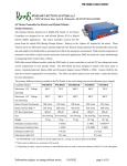
High Accuracy, Customizable
MULTIFUNCTION TESTING DEVICE FOR PHOTOVOLTAIC MODULES
SUPSI-DACD-ISAAC
Campus Trevano
CH - 6952 Canobbio
www.isaac.supsi.ch
SUPSI – DACD – ISAAC
MPPT3☼☼☼ - User Manual
september.2011
TABLE OF CONTENTS
Important safety notice ....................................................................................................................3
Short description ..............................................................................................................................4
Applications ......................................................................................................................................4
Technical specifications ..................................................................................................................5
Performance ......................................................................................................................................5
Box and connections........................................................................................................................6
Front ..............................................................................................................................................6
Mounting the MPPT300..................................................................................................................7
Top lateral ......................................................................................................................................8
Bottom lateral .................................................................................................................................8
Wiring description and schematics.................................................................................................9
Choose of the load resistor ...........................................................................................................28
How to chose a load resistor ........................................................................................................28
Reachable MPP tracking efficiency vs. output load resistor.........................................................28
Table how to calculate the load resistor .......................................................................................30
RS485 network ................................................................................................................................31
Connections system, pin configuration and caracteristics............................................................38
Connections schematics ..............................................................................................................38
Turning on the MPPT3000..............................................................................................................37
Turning off the MPPT3000..............................................................................................................37
Menu.................................................................................................................................................38
Device and Accessories.................................................................................................................40
Software MPPT3K Manager 2.5.3 ..................................................................................................43
Main commands ...........................................................................................................................44
Display online values....................................................................................................................45
Data logging .................................................................................................................................46
Remote IV curve control...............................................................................................................47
Setup ............................................................................................................................................49
Terminal .......................................................................................................................................51
MPP Adjustment ..........................................................................................................................52
MPPT Full Search schema...........................................................................................................53
User Manual - ENG V1.7.doc
2/56
SUPSI – DACD – ISAAC
MPPT3☼☼☼ - User Manual
september.2011
Important safety notice
Warning :
In all cases the assembly and installation must be done by qualified technicians, observing the
national requirements and rules stipulated.
Opening the MPPT3000 or using it incorrectly will result in the immediate loss of the warranty,
(unless for upgrades in agreement with manufacturer)
Warranty:
1 year.
Limitation of liability :
ISAAC - SUPSI cannot control the installation, use and maintenance of the MPPT3000.
Thus, we are not responsible for damages, costs or losses resulting from an installation
which is not in accordance with the regulations or inappropriate use or maintenance.
The customer is always responsible for the use of the MPPT3000 and any other related additional
device.
This device has not been designed nor warranted for use in any critical apparatus with potential
risks of serious harm to people or to the environment.
ISAAC - SUPSI reserves the right to modify their products without previous notice.
User Manual - ENG V1.7.doc
3/56
SUPSI – DACD – ISAAC
MPPT3☼☼☼ - User Manual
september.2011
Short description
The MPPT 3000 is a multifunction testing device for photovoltaic modules. A photovoltaic module,
when connected to the MPPT 3000, is set to work in a MPP tracking mode. The MPPT 3000 also
allows a customized I-V Tracer function. It is possible to connect RTD temperature sensors,
pyranometers or other external sensors. The interaction with the MPPT is possible directly using its
LCD and buttons or through a simple graphical user interface. The PV module energy is dissipated
using an external resistor load with heat sink that must be always connected. This device has been
developed for specific PV module testing at the ISAAC - SUPSI laboratory (TISO group).
−
−
−
−
−
−
−
−
−
−
−
−
−
accurate MPP tracking: maximum 0.5 % error on PMPP tracking
wide voltage and current scalable ranges: up to 200V / 20A / max 250W
optoisolated analog auxiliary outputs in order to measure, using an external measurement
system, the PV module working condition and the auxiliary sensors
built-in independent data logging: internal data storage allowing the use of the MPPT as
datalogger
transportable, compact, wide operating ambient temperature range (from -20°C to +40 °C)
galvanically isolated RS-485 interface: dialog between PC master and one or more MPPTs
I-V Tracer : use of the MPPT3000 as settable IV Tracer
simultaneous Im and Vm measurement
non isolated analog output (optional)
run-time selectable ranges (automatic or manual)
possibility to measure, thanks to a built-in micro-converter and independently from data
loggers or external peripherals, the main meteorological parameters (T, G, …) by means of
auxiliary sensors (sensors are not included)
user friendly management software
IP 20 case
Applications
This electrical equipment is extremely useful for anyone who needs to accurately test photovoltaic
modules such school laboratories, module manufacturers or module providers, testing laboratories
and so on.
Typical applications are:
−
−
−
−
−
sc-Si, mc-Si, a-Si, thin-film accurate module testing
I-V characterization
Energy production test and comparison at outdoor real conditions
Meteorological measurements during module test
Comparison of an existing PV plant behaviour with respect to a reference PV module under
test using the MPPT3000.
User Manual - ENG V1.7.doc
4/56
SUPSI – DACD – ISAAC
MPPT3☼☼☼ - User Manual
september.2011
Technical specifications
General
MPPT power supply
Operating ambient temperature
Case protection grade
Load output resistor
Dimensions
Weight
Photovoltaic module values
PMAX in
VMAX @ 250W
ISC MAX
Vm MIN
Measurements
Voltage measurement ranges
Current measurement ranges
°C
Ω
mm
kg
+24VDC / 8 W +/-10%
from -20 to +40
IP20
from 18 to 47 (Load must always be connected !)
194 x 221 x 162 without cableglands nor cables
5
W
V
A
V
250 (continuous);
150
5 / 10 / 20 (depends on the model)
5
V
200 / 100 / 50 / 25
20A Model: 20 / 10 / 5 /2.5
10A Model: 10 / 5 / 2.5 /1.25
5A Model: 5 / 2.5 / 1.25 / 0.625
0.2
A
Accuracy
%
IV Tracer
Scan rate
min
2/3/4/5/6
Points number
128 / 256 / 512
Sweep Time
s
1.0 to 3.0
IV tracing ad hoc available using the MPPT manager software.
MPP Tracker
Full I-V curve search
Types
Fast MPP fine adjust
Control
Power and voltage
Customizable MPP adjust and Vm adjust available.
Auxiliary opto-isolated analog outputs
from 0 to 10 (proportional to the default represented
4 analog outputs (Vm, Im, RTD 1, RTD 2)
VDC
input ranges)
Short circuit protected outputs. High impedance load required.
Auxiliary analog measurement inputs
Auxiliary input 1
RTD only (PT100)
Auxiliary input 2
RTD only (PT100)
Auxiliary input 3
voltage 0…1V max (autorange from 0..10mV to 0..1V)
Galvanically isolated RS-485 port
Bit rate
bps
115200
Data length
bit
8
Stop bit
bit
1
Parity
Even
Flow control
None
Performance
MPP Tracking
Static MPP tracking efficiency
Dynamic MPP tracking efficiency
IV Tracer
IV tracing difference
DC / DC conversion
Typ. Efficiency (Pout/Pin)
%
%
> 99.5
> 98.0
%
±0.2
%
90.0
This performance test has been carried out at specific conditions, please see the specific data-book
for details.
User Manual - ENG V1.7.doc
5/56
SUPSI – DACD – ISAAC
MPPT3☼☼☼ - User Manual
september.2011
Box and connections
Front
- Power supply
- Display backlight
ESC
MENU
ENTER
- The reset button of the main part (DSP) is placed on the left side of the box.
- On the right side, there is the reset button of the auxiliary part (μController).
When accessing a reset button, please use a non-conductor stick.
User Manual - ENG V1.7.doc
6/56
SUPSI – DACD – ISAAC
MPPT3☼☼☼ - User Manual
september.2011
Mounting the MPPT3000
The MPPT3000 is provided with integrated heat sink for power dispersion.
In order to get maximum power dispersion the box must be mounted in vertical position or with a
maximum tilt of 30° from vertical position , see also following schematics.
Moreover please allow 1 cm minimum gap from heat sink to mounting wall.
min 10mm
min 10mm
max 30°
Mounting schematics
The electrical operating temperature of the MPPT goes from -20°C to +70°C but the ambiance
temperature must not exceed 40°C at maximum power (250 W)
User Manual - ENG V1.7.doc
7/56
SUPSI – DACD – ISAAC
MPPT3☼☼☼ - User Manual
september.2011
Top lateral
1
4
2
3
5
Bottom lateral
6
8
7
User Manual - ENG V1.7.doc
8/56
SUPSI – DACD – ISAAC
MPPT3☼☼☼ - User Manual
september.2011
Wiring description
Connector
1
2
3
4
5
6
7
8
Description
RS-485 line, DB9 male
RS-485 line, DB9 female
Auxiliary analog outputs, DB9 female
Auxiliary input/output of auxiliary part (μController), DB15 male
Power supply of MPPT3000
Input for PV voltage sense measurement
Input for power connection PV module
Output power part (to the load resistor)
WARNING! THE LOAD RESISTOR MUST ALWAYS BE CONNECTED
TO THE MPPT3000 ! Using the MPPT3000 without the load resistors
leads to serious damages.
Connector 1 and 2 :
See chapter RS-485 line.
Connector 3 :
1
2
Output AUX1 (0...10V represents 0...Ufull scale)
Output AUX1 (GND)
3
4
Output AUX2 (0...10V represents 0...Ifull-scale)
Output AUX2 (GND)
5
6
Output AUX3 (0...10V represents 0...AUX_Ch0_full scale)
Output AUX3 (GND)
7
8
Output AUX4 (0...10V represents 0...AUX_Ch1_full scale)
Output AUX4 (GND)
9
not connected
All auxiliary outputs are short circuit protected by means of a 2 kΩ series resistor.
Therefore to measure the output voltage value high impedance input instruments are required.
User Manual - ENG V1.7.doc
9/56
SUPSI – DACD – ISAAC
MPPT3☼☼☼ - User Manual
september.2011
Connector 4 :
Auxiliary measurement part (μC) inputs. Configuration :
_ RTD on AUX IN 1 (AUX_Ch0)
_ RTD on AUX IN 2 (AUX_Ch1)
_ general voltage input on AUX IN 3
The next picture shows how to connect the RTDs and the general purpose voltage input (typically a
pyranometer).
IEXC
1
9
PT100
AUX IN 1
=> AUX OUT 3
& DISPLAY
AUX IN 2
=> AUX OUT 4
& DISPLAY
AUX IN 3
=> DISPLAY
2
10
3
11
PT100
4
12
13
Max 1 VDC
6
AUX IN 3:
The minimum voltage input range is 0..10 mV, the maximum voltage input range is 0..1V. The input
range selection is automatic, just avoid to exceed 1 VDC or the device will be damaged . The
voltage must be always positive (unipolar). The MPPT itself provides the excitation current for the
RTDs.
In the following annexes (A to I) you find all the possibility
how to do right connections.
User Manual - ENG V1.7.doc
10/56
SUPSI – DACD – ISAAC
MPPT3☼☼☼ - User Manual
september.2011
A- AUX-IN CONNECTION Æ 2xPT100, 1x Sensor[V] with intermediaries clamps and shield connected together
User Manual - ENG V1.7.doc
11/56
SUPSI – DACD – ISAAC
MPPT3☼☼☼ - User Manual
september.2011
B- AUX-IN CONNECTION Æ 2xPT100, 1x Sensor[V] with intermediaries clamps and shield connected together
User Manual - ENG V1.7.doc
12/56
SUPSI – DACD – ISAAC
MPPT3☼☼☼ - User Manual
september.2011
C- AUX-IN CONNECTION Æ 2xPT100, 1x Sensor[V] with intermediaries clamps and shield split
User Manual - ENG V1.7.doc
13/56
SUPSI – DACD – ISAAC
MPPT3☼☼☼ - User Manual
september.2011
D- AUX-IN CONNECTION Æ 2xPT100, 1x Sensor[V] with intermediaries clamps and shield split
User Manual - ENG V1.7.doc
14/56
SUPSI – DACD – ISAAC
MPPT3☼☼☼ - User Manual
september.2011
E- AUX-IN CONNECTION Æ 1xPT100, 1x Sensor[V] with intermediaries clamps and shield connected together
User Manual - ENG V1.7.doc
15/56
SUPSI – DACD – ISAAC
MPPT3☼☼☼ - User Manual
september.2011
F- AUX-IN CONNECTION Æ 1xPT100, 1x Sensor[V] and shield connected together
User Manual - ENG V1.7.doc
16/56
SUPSI – DACD – ISAAC
MPPT3☼☼☼ - User Manual
september.2011
G- AUX-IN CONNECTION Æ 1xPT100, 1x Sensor[V] with intermediaries clamps and shield split
User Manual - ENG V1.7.doc
17/56
SUPSI – DACD – ISAAC
MPPT3☼☼☼ - User Manual
september.2011
H- AUX-IN CONNECTION Æ 1xPT100, 1x Sensor[V] and shield split
User Manual - ENG V1.7.doc
18/56
SUPSI – DACD – ISAAC
MPPT3☼☼☼ - User Manual
september.2011
I- AUX-IN CONNECTION Æ 1xPT100 with intermediaries clamps and shield connected together
User Manual - ENG V1.7.doc
19/56
SUPSI – DACD – ISAAC
MPPT3☼☼☼ - User Manual
september.2011
Connector 5 - Power Supply
- Simply connect 2:1 connector to the Power 24V of the MPPT.
- The AC 220V has to be connected only after the Load, PV and Sense.
User Manual - ENG V1.7.doc
20/56
SUPSI – DACD – ISAAC
MPPT3☼☼☼ - User Manual
september.2011
Connectors 6 and 7: PV Module power (Input) - Voltage Sense (Input)
- Check the voltage and the polarity of the photovoltaic module.
- The voltage of the photovoltaic module should in any case NOT exceed the value of 200 VDC (Voc voltage).
- These connections should be done very carefully observing the polarity, any inappropriate voltage or polarity can damage the device.
- All the PV wires for 20A must to be minimum 2.5mm2, greater is better because you have less losses.
- The Sense wires 0.25mm2
- The Sense connections have to be connected with the PV connections near as possible to the module.
The shied of the sense has to arrive till the the PV connection, but it isn’t to be connected!
User Manual - ENG V1.7.doc
21/56
SUPSI – DACD – ISAAC
MPPT3☼☼☼ - User Manual
september.2011
A- Connection MC3 (MPPT3000)- MC3 (PV-Module)
+
white
_
brown
This connection solution is the more easier to assembly and simple if you have to change or dismount the system, but the
most expensive.With the MPPT3000 we supply only the ‘Sense’ connector and cable.
The cost of the Multi-Contact accessories will be around 60-70 EUR, depending on the length of the cables
User Manual - ENG V1.7.doc
22/56
SUPSI – DACD – ISAAC
MPPT3☼☼☼ - User Manual
september.2011
Connection MC3 (MPPT3000)- MC3 (PV-Module)
+White
_ brown
This connection solution is to weld or crimp the sense wirings directly with the MC3 connectors.
You have to weld yourself the MC connector with the cables ‘PV’and ‘Sense’, but is cheaper than the first solution.
With the MPPT3000 we supply only the ‘Sense’ connector and cable.
The cost of the Multi-Contact accessories will be around 30-40 EUR, depending on the length of the cables.
User Manual - ENG V1.7.doc
23/56
SUPSI – DACD – ISAAC
MPPT3☼☼☼ - User Manual
september.2011
C-Connection MC3 (MPPT3000)- MC4 (PV-Module)
+
white
_ brown
This connection solution is exactly as the solution ‘A’, but with MC4 connectors
The costs are similar.
User Manual - ENG V1.7.doc
24/56
SUPSI – DACD – ISAAC
MPPT3☼☼☼ - User Manual
september.2011
D-Connection MC3 (MPPT3000)- MC4 (PV-Module)
+
white
-
brown
_
This connection solution is exactly as the solution ‘B’, but with MC4 connectors.
The costs are similar.
User Manual - ENG V1.7.doc
25/56
SUPSI – DACD – ISAAC
MPPT3☼☼☼ - User Manual
september.2011
E-Connection MC3 (MPPT3000)- without (PV-Module)
+
white
-
brown
_
Clamp 200VDC 20A
This connection solution is the faster and cheaper, but is the less secure, do to the clamp that has to be isolated!!!
.
User Manual - ENG V1.7.doc
26/56
SUPSI – DACD – ISAAC
MPPT3☼☼☼ - User Manual
september.2011
Cable 8 : LOAD (Output)
IIM
MP
EC
PO
OR
CO
RTTA
ON
NN
AN
NE
NTT :: TTH
EC
CTTE
ED
D !!!!!!!!!!!!
HE
E LLO
OA
AD
DM
MU
US
STT A
ALLW
WA
AY
YS
SB
BE
Load connection :
The load MUST always be connected. Using the MPPT3000 without the load resistors
leads to serious damages. There is no polarity.
User Manual - ENG V1.7.doc
27/56
SUPSI – DACD – ISAAC
MPPT3☼☼☼ - User Manual
september.2011
Choose of the load resistor
How to chose a load resistor
A load resistor must always be connected to the power output of the MPPT3000.
Please chose a resistor value between 18 and 47 Ω in order to :
_ not to exceed Iout (I load) < 3.5 A DC
_ not to exceed Vout (V load) < 108 V DC
according to the power output to disperse.
Example :
Power of module = 250 W
Vmpp max > 5 V ( ex : 17 V)
I mpp max < 20 A (ex : 14.7 A)
R load min = 250 / (3.52) = 20.4 Ω
R load max = (1082) / 250 = 46.6 Ω
Æ thus we choose for example 33 Ω / 250 W (or more powerfull)
Æ check in the two charts below if the value of R load chosen is within
required parameters
Example of resistor to use :
HS series heatsink mount resistors
- Resistance range R005 to 100K Ohms
- To 600W
- Tolerance from 0.5%
- High power to volume ratio
- All welded construction
- Available in Non-Inductive Style (Type N)
- High pulse withstand capability
- Connection variation available
Æ
REMEMBER TO MOUNT LOAD RESISTORS ON A SUITABLE HEAT SINK
Reachable MPP tracking efficiency vs. output load resistor
The maximum power point tracking efficiency depends also on the chosen output load resistor.
As mentioned in the previous sub-chapter, the value of this resistor can vary between 18 and 47 Ω.
The following charts show the MPP tracking efficiency limits vs. output load resistor.
User Manual - ENG V1.7.doc
28/56
SUPSI – DACD – ISAAC
MPPT3☼☼☼ - User Manual
september.2011
Iin = f(Uin) with maximum MPP tracking error percentage limits using 18 Ω output resistor
100
Iin [A]
10
1
Inside the area limited by this lines, the MPPT can
reach the 99.5 % of MPP tracking efficieny (0.5% error).
0.1
1
5V limit
0.5
10
100
1000
Uin [V]
0.5
1
1
1.5
1.5
2
2
250W Limit
Iin = f(Uin) with maximum MPP tracking error percentage limits using 47 Ω output resistor
100
Iin [A]
10
1
Inside the area limited by this lines, the MPPT can
reach the 99.5 % of MPP tracking efficieny (0.5% error).
0.1
1
5V limit
0.5
10
100
1000
Uin [V]
0.5
1
1
1.5
1.5
2
2
250W Limit
It can be seen that most of the working area is inside the by the black lines, which describe the
99.5 % efficiency limits. Only in extreme conditions the efficiency can go slightly below this limit.
However, if the MPPT is used properly, the declared MPP tracking efficiency is respected, as it has
been proved during the MPPT practical test.
User Manual - ENG V1.7.doc
29/56
SUPSI – DACD – ISAAC
MPPT3☼☼☼ - User Manual
Table how to calculate the load resistor
User Manual - ENG V1.7.doc
30/56
september.2011
SUPSI – DACD – ISAAC
MPPT3☼☼☼ - User Manual
september.2011
RS485 network
The MPPT3000 devices can be connected to a master PC through a RS485 network. In this way it
is possible to fully exploit the potential of the device using the specific user friendly management
software. The following scheme shows the correct wiring of the MPPT3000 to the RS485 network.
USB
USB-RS485
Terminator
...
RS485
F
M
F
M
F
M
M
F
M
F
M
F
MPPT 3000
#001
MPPT 3000
#002
MPPT 3000
#NNN
At the end of the RS485 line there must be a terminal resistor, which can varies depending on the
manufacturer of the USB/RS485 adapter and on the cables length. This terminal resistor must be
wired between pin 1 (DATA+) and pin 9 (DATA–) of the DB9 connector.
DB9 for RS232 pinout1
Data Carrier Detect
RxD
TxD
Data Terminal Ready
Signal Ground
Data Set Ready
Request to Send
Clear to Send
Ring Indicator
Pin
1
2
3
4
5
6
7
8
9
DB9 for RS485 pinout2
DATA+
Not connected
Not connected
Not connected
GND
V+
Not connected
Not connected
DATA-
To dialog with one or more MPPTs use only the “MPPT Manager” software. This software allows
the user to manage one or more MPPTs easily.
RS-485
Standard
Physical Media
Network Topology
Maximum Devices
Maximum Distance
Mode of Operation
Maximum Baud Rate
Voltage Levels
Mark(1)
Space(0)
Available Signals
1
2
EIA RS-485
Twisted Pair
Point-to-point, Multi-dropped, Multi-point
32 drivers or receivers
1200 metres (4000 feet)
Differential
100 kbit/s - 10 Mbit/s
-7 V to +12 V
Positive Voltages (B-A > +200 mV)
negative voltages (B-A < -200 mV)
Tx+/Rx+, Tx-/Rx- (Half Duplex)
Tx+, Tx-, Rx+, Rx- (Full Duplex)
Defined by the RS232 standard.
Selected for the MPPT3000 project.
User Manual - ENG V1.7.doc
31/56
SUPSI – DACD – ISAAC
MPPT3☼☼☼ - User Manual
Connections schematics
User Manual - ENG V1.7.doc
32/56
september.2011
SUPSI – DACD – ISAAC
User Manual - ENG V1.7.doc
MPPT3☼☼☼ - User Manual
33/56
september.2011
SUPSI – DACD – ISAAC
User Manual - ENG V1.7.doc
MPPT3☼☼☼ - User Manual
34/56
september.2011
SUPSI – DACD – ISAAC
User Manual - ENG V1.7.doc
MPPT3☼☼☼ - User Manual
35/56
september.2011
SUPSI – DACD – ISAAC
User Manual - ENG V1.7.doc
MPPT3☼☼☼ - User Manual
36/56
september.2011
SUPSI – DACD – ISAAC
MPPT3☼☼☼ - User Manual
september.2011
Turning on the MPPT3000
1. After wiring the device according to the manual specifications, unplug the PV module from
the MPPT3000.
2. Verify that the full-scale voltage (Ufull scale) and the full-scale current (Ifull scale) are never
exceeded. Every time a PV module is replaced, verify again that the settings for
Ufull scale and Ifull scale are correct. If these requirements are met, go to 7.
3. Turn the device on and wait until the default writing appears on the display3.
4. Set the Ufull scale and Ifull scale in order that the PV module never exceeds the chosen values.
The set-up can be done directly on MPPT3000 or on the graphical interface of the provided
software.
5. Save the settings for Ufull-scale and Ifull-scale. Here again this can de done directly on the
MPPT3000 or by the software.
6. Turn the MPPT3000 off.
7. Turn the device on and wait until the default writing appears on the display4.
8. Verify that the settings for Ufull-scale and Ifull-scale have been loaded correctly.
9. Plug the PV module to the device.
10. At this stage, the MPPT is operating and can communicate with the master PC through the
provided software, performing the requested instructions.
Turning off the MPPT3000
To switch the MPPT off is recommended to use the shutdown command, this command disables
the data logging and prepares the MPPT to be switched off.
1.
2.
3.
4.
Open the MPPT Manager software.
Select the Terminal Folder.
Press the “Shutdown” button.
Wait the MPPT answer.
Now is safe to turn off the MPPT3000.
Note: After the shutdown command is sent, the data logging is disabled. To restore the normal
function mode the MPPT must be restarted either switching off and re-switching on the power
supply or using the reset button.
3
The time necessary for starting (software load to the processor and initialization) may varies slightly but it is
generally about 30 sec.
4
See previous remark.
User Manual - ENG V1.7.doc
37/56
SUPSI – DACD – ISAAC
MPPT3☼☼☼ - User Manual
september.2011
Menu on the MPPT’s display
Introduction about the MPPT Menu
Three alphanumeric characters help the user to browse the menu.
The first character is used to define the level (Level 0 → no sign, Level 1 → single point, Level 2 → 2 points).
The second and the third characters show the position number of the selected lower level.
Examples:
1
2
0
2
2
0
2
2
1
3
0
0
This is an indicative representation, not a full representation.
'
'
"
0
0
0
0
2
2
1
3
Level 0 is the higher level, it represents the main groups.
Level 1 is the level used to browse and select the voices inside a main group.
Level 2 is the lower level, when the user is in this level he can modify the chosen voice. Only the voices that are available in level 2 can be modified directly through the MPPT.
Only the most important voices can be modified directly using the MPPT interface (buttons and scroll).
The other voices are only accessible using the MPPT Manager software, which also provides an easy access to all the features of the MPPT3000.
Menu Levels
Scroll
Description
1 2 3 4 5 6 7 8 9 10 11 12 13 14 15 16
ESC
Enter
0
1
2
Default
0
0
0
0
0
0
0
0
0
0
0
0
0
1
0
0
2
0
0
3
0
0
4
0
Um, Pm (Normal functioning)
Im, Power part duty cycle
Um, Pm (Power adjustment)
Im, Power part duty cycle
Um, Pm (Voltage adjustment)
Im, Duty Cycle
Um, Pm (MPP full search)
Im, Power part duty cycle
Date, Week day
Hour
E tot
E day
PV module Type
DSP Software version
uController Software version
x
x
x
x
x
x
x
x
d
h
E
E
M
a
D
x
x
x
x
x
x
x
x
d
h
t
d
o
b
S
u
x
x
x
x
x
x
x
x
.
:
x
x
d
c
P
C
.
.
.
.
.
.
.
.
m
m
x
x
u
d
x
x
x
x
x
x
x
x
m
m
x
x
l
e
S
S
x
x
x
x
x
x
x
x
.
:
x
x
e
f
W
W
y
s
x
x
g
V
A
V
A
V
A
V
A
y
s
x
x
T
h
x
x
→ x
x
← x
x
# x
# x
A
x
x
x
x
x
x
x
x
b
x
x
y
i
a
a
x . x
W h
x . x
W h
e
k l m n o p
c d e f g h
c d e f g h
x
x
p
j
b
b
x
x
x
x
x
x
x
x
c
.
.
.
.
.
.
.
.
x
x
x
x
x
x
x
x
W
%
W
%
W
%
W
%
Next
Nothing
Next / Previous L0
Next
Nothing
Next / Previous L0
Next
Nothing
Next / Previous L0
Next
Nothing
Next / Previous L0
Next
Nothing
Next / Previous L0
Next
Nothing
Next / Previous L0
Next
Nothing
Next / Previous L0
Next
Nothing
Next / Previous L0
Level UP
Level DOWN
Next / Previous L0
Level UP
Level DOWN
Next / Previous L1
Level UP
(don't load in RAM)
Enter
Change state
Level UP
Nothing
Next / Previous L1
Level UP
Nothing
Next / Previous L1
Level UP
Nothing
Next / Previous L1
Level UP
Nothing
Next / Previous L1
Level UP
Nothing
Next / Previous L1
Low Refresh Info
1
99
0
1
0
0
1
0
1
1
1
0
1
2
0
1
3
0
1
4
0
1
5
0
1
6
0
1
7
0
1
8
0
1
9
0
1
10
0
1
11
0
1
12
0
1
13
0
1
14
0
1
15
0
1
15
1
1
16
0
1
16
1
1
17
0
1
17
1
1
18
0
1
19
0
1
20
0
1
1
21
22
0
0
RS485 network ID
PV module manufacturer
PV module type
PV module serial number
PV module database ID
PV module ID code
PV module position
Auxiliary output 2 external datalogger
associated channel
Auxiliary output 3 external datalogger
associated channel
PV module MPP power @ STC.
L o w
R e f r e s h
I n f o
( S e t u p 1
M P P T
I D
S e
t
M P P T
M
a
M
a
S
a
D
a
b
o
b
e
b
a
n
c
d
c
r
c
t
M
a
P
a
C
o
b
o
b
h
d
c d
s i
c d
u
d
u
d
i
d
a
C h
@
PV module MPP current @ STC.
I m
@
PV module MPP voltage @ STC.
V m
@
PV module short circuit current @ STC
I
PV module open circuit voltage @ STC
V o c
PV module fill factor.
F F
MPPT current mesuring shunt resistor.
R s h u n
s
c
I D
f a c t u r e r
e f g h i j k l
l e
T y p e
e f g h i j k l
a l
N r
e f g h i j k l
b
M o d
I D
x x
I D
C o d e
e f g h i j k l
t i o n
e f g h i j k l
A u x
2
x x
A u x
3
x x
S T C
x x x .
S T C
x x x .
S T C
x x x .
@
S T C
x x x .
@
S T C
x x x .
P m
x
x
x
.
S e
t
V
R a n g e
Default current range
(Auxiliary output 1 refers to this value)
I
S
R s h u n
t
V
PV module cell area
C
PV module area
M
PV module cells in serie
C
PV module cells in parallel
C e
l
l
Output resistor
R o u
t
User Manual - ENG V1.7.doc
s
m
m
x
m
m
x
x
x
x
x
x
x
x
i
n
x
t
x
R a n g
x
R a n g e
x x x
e t
I
R a n g
x x x
e l l
A r e a
x x x .
o d u l e
A r e
x x x .
e l l s
i n
s
S e
m
t
x
Default voltage range
(Auxiliary output 0 refers to this value)
0 1
)
x
x
x x
e
x x
.
.
. x x
e
. x x
x
a
x
e
x
p a
x
x
x
r
x
r
x
x
x
x
38/56
'
x
"
x
'
n
'
n
'
n
'
x
'
n
'
n
'
x
'
x
'
x
'
x
'
x
'
x
'
x
'
x
'
0
x
0
x
0
o
0
o
0
o
0
x
0
o
0
o
0
x
0
x
0
1
1
1
1
1
1
m
" 0
m
' 1
x
" 0
x
' 1
x
" 0
x
' 1
c m
' 1
m
' 2
x x
' 2
x x
' 2
x
0
x
1
x
1
p
2
p
3
p
4
x
5
p
6
p
7
x
8
x
9
W
0
A
1
V
2
A
3
V
4
%
5
Ω
1
Ω
6
V
1
V
7
A
1
A
8
2
9
2
0
x
1
x
2
Ω
Level UP
Nothing
Next / Previous L1
Level UP
Nothing
Next / Previous L1
Level UP
Nothing
Next / Previous L1
Level UP
Nothing
Next / Previous L1
Level UP
Nothing
Next / Previous L1
Level UP
Nothing
Next / Previous L1
Level UP
Nothing
Next / Previous L1
Level UP
Nothing
Next / Previous L1
Level UP
Nothing
Next / Previous L1
Level UP
Level DOWN
Next / Previous L1
Level UP
(don't load in RAM)
Enter
Change state
Level UP
Level DOWN
Next / Previous L1
Level UP
(don't load in RAM)
Enter
Change state
Level UP
Level DOWN
Next / Previous L1
Level UP
(don't load in RAM)
Enter
Change state
Level UP
Nothing
Next / Previous L1
Level UP
Nothing
Next / Previous L1
Level UP
Nothing
Next / Previous L1
Level UP
Nothing
Next / Previous L1
Level UP
Level DOWN
Next / Previous L1
SUPSI – DACD – ISAAC
MPPT3☼☼☼ - User Manual
september.2011
Setup
2
2
99
0
0
0
2
0
1
2
1
0
2
1
1
2
2
0
2
2
1
2
3
0
2
3
1
2
4
0
2
4
1
2
5
0
2
5
1
2
6
0
2
6
1
2
7
0
2
7
1
2
8
0
2
8
1
2
9
0
2
9
1
2
10
0
2
10
1
2
11
0
2
11
1
2
12
0
2
12
1
2
13
0
2
14
0
2
15
0
2
16
0
2
16
1
2
17
0
2
18
0
2
18
PWM duty cycle manual setting.
(use this only for debug purposes)
MPP full search.
H i g h
R e f r e s h
I n f o
( S e t u p 2
M a n u a l
P W M
x x x
x x x
M P P
S e
MPP full search type
MPP full search scan rate
MPP full search sweep time
MPP full fearch dead time
MPP adjustement state (ON/OFF)
.
.
t
M P P
M P P
S
T
M
R
S
S
M
S
S
S
M
D
S
D
M
e
y
P
a
e
c
P
w
e
w
P
e
e
e
P
t
p
P
t
t
a
P
e
t
e
P
a
t
a
P
S e
t
MPP adjustement start window
M P P
MPP adjustement end window
S
S
M
Voltage adjustement state (ON/OFF)
S
E
V
x x x V
x x x A
F S
F S
x
x
x
x
F S
M P P
F S
e
F S
S c a n
e
n
e
e
d
d
M P
R
F S
p
M P
p
F S
T
M P
T
A d
P
a
t
t
F S
e
x
x
x
x
x
.
T
P
T
F S
x
x
.
x x
F S
x x
.
x
P
.
A d
A d
S
x
A
x
E
x
A
x
V m
x
x
x
x
A d
x
d
x
W
x
j
x
W
x
j
x
i n
x x
x x
i n
x x
x
Voltage adjustement end window
S
S
V
Automatic IV Tracer state (ON/OFF)
S
E
I
S
S
I
R
I
e t
I V
T r
t a t e
V
T r
S c a n
a t e
x x
h
V
T r
P o i n t s
I
V
Main datalogging scan rate
Autorange state (ON/OFF)
Restore default setup
1
x
j
W
x
e t
V m
A d j
W i n
x
m
A d j
E
W
x
e t
V m
A d j
W i n
x
V
T r
S t a t
T
j
x
d
x
j
V m
Ad hoc IV Tracer points number
(Automatic IV Tracer always has 256 pts)
IV Tracer seweep time
x
j
M P P
A d
x
Voltage adjustement start window
Automatic IV Tracer Scan Rate
.
.
T y p e
j
x
e t
M P P
W i n
x
P P
A d j
x
e t
M P P
W i n
x
m
A d j
S e
x
x
0 2
)
S
i n
x x x
x x x
i n
x x x
x x
e
x
x
r
D
R
S
L
A
S w e e p
T
x x .
a t a
L o g g i n g
a t e
x
e t
D a t a
o g g i n g
R a t e x
u t o r a n g e
R
D
P
t
e s t o r e
e f a u l t
S e
r e s s
E n t e
o
R e s t o r e
S
D
S
i
P
t
L
i
P
t
S
i
P
t
L
i
P
t
a
S
a
n
r
o
o
n
r
o
a
n
r
o
o
n
r
o
t
r
u p
S e
'
0 0
x
x
'
A
"
A
'
W
%
1
C
1
C
2
x
1
x
3
s
1
s
4
s
1
s
5
s
1
s
6
C
1
C
7
x
1
x
8
x
1
x
9
C
1
C
0
x
1
x
1
x
1
x
2
C
1
C
3
m
4
x
5
s
6
m
1
m
7
C
0
x
x
0
B
0
B
0
x
" 0
x
' 0
x
" 0
x
' 0
x
" 0
x
' 0
x
" 0
x
' 0
A B
" 0
A B
' 0
x x
" 0
x x
' 0
x x
" 0
x x
' 0
A B
" 0
A B
' 1
x x
" 0
x x
' 1
x x
" 0
x x
' 1
A B
" 0
A B
' 1
x
' 1
x x
' 1
x
' 1
x
" 0
x
' 1
A B
' 2
?
" 0
t u
1
p
Level DOWN
Next / Previous L0
Level UP
Level DOWN
Next / Previous L1
Level UP
Change Quad
Encoder Step
Change Duty Cycle B
Level UP
Level DOWN
Next / Previous L1
Level UP
(don't load)
Load into RAM
Change state
Level UP
Level DOWN
Next / Previous L1
Level UP
(don't load)
Enter
Load into RAM
Change state
Level UP
Level DOWN
Next / Previous L1
Level UP
(don't load)
Enter
Load into RAM
Change state
Level UP
Level UP
Level DOWN
Next / Previous L1
Level UP
(don't load)
Enter
Load into RAM
Change state
Level UP
Level DOWN
Next / Previous L1
Level UP
(don't load)
Enter
Load into RAM
Change state
Level UP
Level DOWN
Next / Previous L1
Level UP
(don't load)
Load into RAM
Change state
Next / Previous L1
Level UP
Level DOWN
Level UP
(don't load)
Load into RAM
Change state
Level UP
Level DOWN
Next / Previous L1
Level UP
(don't load)
Load into RAM
Change state
Level UP
Level DOWN
Next / Previous L1
Level UP
(don't load)
Load into RAM
Change state
Level UP
Level DOWN
Next / Previous L1
Level UP
(don't load)
Load into RAM
Change state
Level UP
Level DOWN
Next / Previous L1
Level UP
(don't load)
Load into RAM
Change state
Level UP
Level DOWN
Next / Previous L1
Level UP
(don't load)
Load into RAM
Change state
Level UP
Nothing
Next / Previous L1
Level UP
Nothing
Next / Previous L1
Level UP
Nothing
Next / Previous L1
Level UP
Level DOWN
Next / Previous L1
Level UP
(don't load)
Load into RAM
Change state
Level UP
Level DOWN
Next / Previous L1
Level UP
Level DOWN
Next / Previous L1
Level UP
(don't restore)
Restore default LRI
into RAM
Nothing
Level UP
Level DOWN
Next / Previous L0
Save/Load
3
99
0
3
0
0
3
0
1
3
1
0
3
1
1
3
2
0
3
2
1
3
3
0
3
3
1
Save Low Refresh Info (Setup1) into
MPPT flash memory
Load Low Refresh Info (Setup1) from
flash memory to MPPT RAM
Save High Refresh Info (Setup2) into
MPPT flash memory
Load High Refresh Info (Setup2) from
flash memory to MPPT RAM
v
P
v
t
e
/ L
P a
L
F
s
a v
L
D
s
o a
S
F
s
a v
S
D
s
o a
o
r
R
l
E
e
R
S
E
d
e
l
E
e
e
S
E
d
a d
t
I
a s h
n t e
L R
I
P
R
n t e
L R
t u p
a s h
n t e
S e
t u p
P
R
n t e
S e
u C o n v e
r
t
e
r
x
° C x
x V x
x
x
a
t
e
v
t
e
a
t
e
e
e
o
s
S
d
o
s
L
e
o
s
S
d
o
s
L
0 3
' 0 0
A b c
" 0 1
?
r
I
' 0 1
A M ? A b c
r
" 0 1
I
' 0 2
?
r
" 0 1
t u p
' 0 3
A M ? A b c
r
" 0 1
t u p
Level UP
Level DOWN
Next / Previous L1
Level UP
(don't save)
Enter
(Save)
Nothing
Level UP
Level DOWN
Next / Previous L1
Level UP
(don't load)
Enter
(Load)
Nothing
Level UP
Level DOWN
Next / Previous L1
Level UP
(don't save)
Enter
(Save)
Nothing
Level UP
Level DOWN
Next / Previous L1
Level UP
(don't load)
Enter
(Load)
Nothing
Level UP
Level DOWN
Next / Previous L0
Level UP
Nothing
Next / Previous L1
uConverter
4
99
0
4
0
0
T ch0, T ch1
U ch3, T internal sensor
User Manual - ENG V1.7.doc
x
x
x
.
.
x
x
x
x
39/56
0 4
x
x
.
.
x
x
x
x
° C
° C
SUPSI – DACD – ISAAC
MPPT3☼☼☼ - User Manual
Device & Accessories
included:
1)
2)
3)
4)
5)
6)
MPPT3000 Device
MPPT3000 User Manual
MPPT3K Manager Software (CD and user Manual)
power supply 24V
load cable 1.5m
sense cable 1.5m
extras (on demand):
7) MC connectors or assembled cablings
8) Customized Load with ARCOL resistors
9) PT100 (temperature sensor)
10) Wiring and clamps to connect 2 PT100 and 1 phyranometer
11) RS485 Æ USB converter (ADAM)
12) RS485 Æ USB converter (Trinamic)
13) RS485 Æ MPPT3000 cable and connectors 10.0m (or only connectors)
14) AUX-IN cable configurated 1.0m (or only connectors)
User Manual - ENG V1.7.doc
40/56
september.2011
SUPSI – DACD – ISAAC
MPPT3☼☼☼ - User Manual
september.2011
8
11
3
2
10
4
13
14
1
9
7
User Manual - ENG V1.7.doc
6
5
41/56
SUPSI – DACD – ISAAC
User Manual - ENG V1.7.doc
MPPT3☼☼☼ - User Manual
42/56
september.2011
SUPSI – DACD – ISAAC
MPPT3☼☼☼ - User Manual
september.2011
Software for
SUPSI – DACD – ISAAC 2011
MPPT3K simple graphical user interface
User Manual - ENG V1.7.doc
43/56
SUPSI – DACD – ISAAC
MPPT3☼☼☼ - User Manual
september.2011
MPPT3K Manager
MPPT3K Manager is an utility that allows to remotely control an MPPT 3000 device, and to easily perform
tasks that otherwise would require a terminal program and a deep knowledge of the MPPT 3000
communication protocols.
The communication with the MPPT 3000 is done via the RS-485 port (normally an adapter USB <-> RS485 is utilized, see MPPT 3000 manual for more information).
NOTE: This manual does not intend to explain how to test photovoltaic modules, but only to explain the
program functionalities.
Main Commands:
A1
A2
A3
A4
A5
A6
A1. Tab selector
Clicking on this area gives access to the five main areas of the program:
- Online values: show data that is currently measured by the MPPT
- Data logging: store data measured by the MPPT with an adjustable time step
- Remote IV curve control: allows to request the MPPT to execute IV curves
- Setup
- Terminal
A2. Serial port for RS485 or adapter
This control allows to select the port that connects the PC with the MPPTs (via RS-485 or adapter)
Note: this field is editable, click on the text to modify it with another port number
A3. MPPT number
To communicate with a specific MPPT, it is necessary to insert its identification number in this field
A4. Status led
The led is green when the program is ready
The led is grey when the program is communicating or computing
The led is red when an error occurs (e.g. communications errors)
Note: It is not possible to communicate with a MPPT when the device is adjusting the MPP, executing an
IV-tracer, executing a full MPP search or internal special sub-routines
A5. Close the program
Stop the execution of MPPT3K manager
A6. Information button
Open a window with information about the software
User Manual - ENG V1.7.doc
44/56
SUPSI – DACD – ISAAC
MPPT3☼☼☼ - User Manual
september.2011
DISPLAY ONLINE VALUES:
This section of the program gives the access to the values currently measured from the connected device.
It is also possible to plot multiple measurements to visualize variations.
B3
B4
B5
B6
B1
B2
B1. Pyranometer sensibility
Set the pyranometer sensibility to show the correct irradiance values in W/m²
B2. Refresh online values
Retrieve the values currently measured from the selected MPPT. These values are shown on the left
panel and added to the plot
B3. Show plot buttons
Show/hide selected plots
B4. Clear
Clear the graph
B5./B6. Auto refresh
When activated, the online values are automatically fetched every N seconds. The refresh
frequency is set in the refresh every N seconds (B6) box.
User Manual - ENG V1.7.doc
45/56
SUPSI – DACD – ISAAC
MPPT3☼☼☼ - User Manual
september.2011
DATA LOGGING:
This function allows to retrieve and store data from the MPPT with an adjustable frequency.
C1
C2
C3
C4
C5
C6
C7
C1. Output path selection
Set the output .cvs file
C2. Time between measurements
Set the frequency between measurements in minutes
C3. MPPT selection
When using the datalogging function, the MPPT Nr. (A3) control box is disabled. Instead, it is possible to
select multiple MPPTs to query, adding their identification number to the list.
Remark: always consider the communication time between the program and the MPPT: when selecting a
large number of MPPTs, the time between measurements (C2) has to be adjusted to avoid that a new
cycle of queries will begin before the end of the current one.
Remark: each MPPT is queried sequentially, so do not expect to obtain measurements from multilple
MPPTs exactly at the same time
C4. Check selected MPPT
This function checks the values entered in the previous list (C3). If an MPPT number does not correspond
to a reachable MPPT, the program asks to remove it from the list.
C5. Start/Stop buttons
Use these buttons to start/stop data acquisition
C6. Current measurements window
Shows data acquired during execution
C7. Errors list
Connection errors are shown in this list
User Manual - ENG V1.7.doc
46/56
SUPSI – DACD – ISAAC
MPPT3☼☼☼ - User Manual
september.2011
REMOTE IV CURVE CONTROL:
The MPPT3K Manager allows to execute remote ad-hoc IV curve measurements. It is possible to save
the output values to file, and to plot graphs. This Ad-hoc IV curve has not to be confused with the IVtracer function embedded in the MPPT (for this feature see the setup section, MIVE commands).
Note: The periodically MPPT3K IV-curve execution feature of the MPPT3K is not available yet.
D1
D2
D3
D4 D5 D6 D7 D8 D9
D10
D11
D1. Multiple MPPT IV Curve
To execute an ad-hoc IV Curve on multiple MPPTs, insert the identification number of the devices in the
array. The IV curve will be executed on every selected MPPT sequentially (not in the same time!). If the
array is empty, the IV Curve will be executed on the MPPT selected in MPPT number (A3) control box.
Use button Empty array (D3) to empty the array
D2. Execute IV
Begin the execution of the IV curves
D3. Empty array and use main MPPT number
Use this button to empty the array Multiple MPPT IV curve (D1)
D4. Autoexecute
When activated, an IV curve is executed every N seconds, where N is the value set in # seconds
countdown (D6)
D5. Read from file
Read a measurement file previously stored and plot the graph
User Manual - ENG V1.7.doc
47/56
SUPSI – DACD – ISAAC
MPPT3☼☼☼ - User Manual
september.2011
D6. # seconds countdown
Select the seconds between each IV curve (used only with autoexecute (D4))
D7. Graph title
Insert a title for the printed graph
D8. Select printer
Select the printer for the print (D11) function
D9. Open measure “.csv”
Open a selected .csv file in excel (excel must be installed)
D10. Delete measure “.csv”
Delete a selected .csv file
D11. Print
Print the IV curves shown on the chart on the left
IV tracer headers
Data received from a MPPT via RS-485:
BEGIN
09:51 MPPT: 1
10/05/07/
4 09:51:43 50
1.25
0
0
0
0.012 -246.702
0.04
0,000000 1,144043
0,000000 1,144043
0,000000 1,144165
…
…
SweepTime:
BEGIN
[time] MPPT: [mppt number]
[date] [day (1=mon, 2=tue, …)] [time] – SweepTime: [IV Sweep Time]
[Um_coef ] [Im_coef]
[aux0_unit_code] [aux1_unit_code] [aux2_unit_code]
[aux_value0] [aux_value1] [aux_value2]
[iv_U] [iv_I]
…
[iv_U] [iv_I]
2000
//multiplication coefficient*
//not used yet
//meteo data (T1, T2, G)
* The values received from the MPPT need to be multiplied by a coefficient to obtain a correct value (this
multiplication is already done by the MPPT3K manager)
User Manual - ENG V1.7.doc
48/56
SUPSI – DACD – ISAAC
MPPT3☼☼☼ - User Manual
september.2011
SETUP:
Setup allows to manage the most important settings of the MPPT3K (MPP search, IV-Tracer and Energy
settings). It is also possible to setup informations about the modules that are connected to the device.
These settings are stored in the MPPT RAM and are saved into the MPPT flash memory.
E20
E1
MPP
Full
Search
E2
E3
MPP
Adjust
E4
E5
E6
E7
Vm
Adjust
IV
tracer
E8
E9
E23
E10
E11
E12
E13
E14
E21
E22
E15
E16
E17
E18
E19
E1. Low refresh info (LRI)
Read or set the values of the low refresh information (see MPPT user manual for more details)
E2. Quick disable all
Disable MPP Adjust, Vm Adjust, IV tracer and MPP full search on the MPPT3K. This can be useful, when
communicating with the MPPT, to avoid communication problems (the MPPT3K doesn’t respond when
executing MPP adjusting, commands, and other internal sub-routines).
E3. Quick enable all
Enable all the adjustment and search features on the MPPT
E4./E6. Download main datalogger data (Main=module / uC=meteo)
Download the stored datalogger values to a file in file store location (E22)
The all/last switch allows to select the download mode
It is possible to change the rate that these informations are stored, changing the value of the field
Datalogging rate.
File row format: Date;time;E.Total;E.Day;Vm;Im / Date;time;IN1;IN2;IN3
E5./E7. Download all/last
When the option all is selected, all the datalogger memory is downloaded from the MPPT.
When last is selected, the program reads the last measure present in the output file, and downloads only
the missing measurements.
Warning: If the datalogging rate has been changed use download all (E5/E7) to avoid data loss.
User Manual - ENG V1.7.doc
49/56
SUPSI – DACD – ISAAC
MPPT3☼☼☼ - User Manual
september.2011
In both modes data is added to the previous downloaded data file, if present.
E8. Get MPPT time
Ask date and time to the MPPT3K Real Time Clock
E9. Set MPPT time
Sets the time of the PC to the MPPT
E10. Enable buttons
Enable following critical/special buttons (E11, E12, E13, E14)
SPECIAL BUTTONS:
ATTENTION: The following buttons will permanently erase the selected MPPT memory!
E11. Reset daily energy
Reset the daily energy counter
E12. Reset total energy
Reset the total energy counter
E13. Erase energy flash blocks
Erase all flash blocks where datalogger data is stored
E14. Restore default setup (in MPPT ram)
Restore the default MIVE setup in ram. The MPPT internal flash memory is not modified.
Warning: Use save (E15) to store default values into the flash too, or at the next reboot of the device, old
flash data will be charged into the ram
E15. LRI management
GET: fetch LRI values from MPPT RAM, and display them into the MPPT3K manager
SET: load LRI values from the MPPT3K manager to the MPPT RAM
SAVE: Save MPPT3K RAM LRI values to the flash (in the next reboot these values will be charged in
MPPT RAM)
LOAD: fetch MPPT3K LRI flash values, and set to the MPPT3K MPPT RAM
E16. Save LRI to file
Download MPPT3K LRI RAM values to the MPPT3K manager, and store them into a file
E17. Read LRI from file
Read LRI information from a file, and show them in the MPPT3K manager
E18. Save MIVE to file
Download MPPT3K MIVE RAM values to the MPPT3K manager, and store them into a file
E19. Read MIVE from file
Read MIVE information from a file, and show them in the MPPT3K manager
E20. MPP search, IV-tracer and Energy (MIVE)
Read or set the values of the MPP, IV-tracer and energy (MIVE). See MPPT user manual for more
information
E21. MIVE management
GET: fetch MIVE values from MPPT3K RAM, and displays them into the MPPT3K manager
SET: load MIVE values from the MPPT3K manager to the MPPT3K RAM
SAVE: Save MPPT3K RAM MIVE values to the flash (at the next reboot these values will be charged in
MPPT RAM)
LOAD: fetch MPPT3K MIVE flash values, and set to the MPPT3K MPPT RAM
E22. File store location
Directory where IV Curve, datalogger values, and settings files are stored
E23. Decimal sep
International settings: Use “.” or “,” as decimal separator in the datalogging csv files
User Manual - ENG V1.7.doc
50/56
SUPSI – DACD – ISAAC
MPPT3☼☼☼ - User Manual
september.2011
TERMINAL:
This is an integrated remote terminal, for communicating with the selected MPPT.
IMPORTANT: The terminal should be used only by trained personnel
F2
F1
F3
F4
Note: When using the Terminal, all other MPPT3K manager functions are disabled
F1. Send
Send the command to the selected MPPT3K (A3.)
F2. Read
Activate the button to read responses on the serial port
F3. Erase
Delete history from the response window
F4. Shutdown MPPT
Prepare the MPPT to be switched off
Example of that can be executed in the terminal:
Format:
‘command’’values’
Example:
170
(PING, communication test)
Example:
48010
(read last 10 datalog values)
User Manual - ENG V1.7.doc
51/56
SUPSI – DACD – ISAAC
MPPT3☼☼☼ - User Manual
september.2011
MPP ADJUSTMENT
MPP and Vm Adjust
Pm ADJUST (MPP Adjust):
Is a local search used to correct irradiation variations more than 0.5% (with default start window).
Tested every 200ms
Vm ADJUST:
Is a local search used to correct temperature variations more than 0.5% (with default start window).
Tested every 200ms
This two adjustments are enough to follow the MPP in every conditions, but for morning, shadow or other
conditions a third control is suggested: the mpp full search
MPPT FULL SEARCH
This is useful in certain conditions:
- In case of defective module,
- partial shadows
- morning and evening or bad weather
- low irradiance
e.g. in case of two peaks in the power, the mpp full search assure to follow the highest
P
V
As said, the MPP Full Search is not necessary in normal conditions , and can be set up to the max value of 10
minutes.
MPP FULL SEARCH SWEEP TIME
The sweep time can be set from 1.347 to 10 seconds depending on the MPP Full Scan Type:
MPP Full Scan Type
Measure’s number of points
0
1
2
512
256
128
Minimum sweep time
[s]
5.263
2.652
1.347
Max sweep time [s]
10
10
10
The sweep time can be set depending on module characteristics and technology.
NOTE: when the MPPT3K is executing a MPP FULL SEARCH, the analog out and the datalogged values are
set to the last value before the search.
User Manual - ENG V1.7.doc
52/56
SUPSI – DACD – ISAAC
MPPT3☼☼☼ - User Manual
september.2011
MPP Full Search scheme:
Precision for very low current (< 10% of full
range) is > 99.5% as in specifications
In normal case > 99.7%
DPWM_B_MPP
stabilization
Isc=>D=100%
Check for variation every 200ms
Last MPP
MPP
Pm or Vm Adjust on next
variation > 0.5%
T1
T2
T3
Sweep
time
t
T4 T5
Pm Adjust (fine adjust)
MPP Full Search
While adjusting, processed Vm and Im values (so
the calculated energy) and the respective auxiliary
analog output remain hold
In case of low irradiation, without autorange is better to have high “Measure’s number of points” and high
sweep time. This is not necessary with autorange.
Working with the lowest “MPP Full Scan Sweep Time”, lowest number of points and low current, the error will
always be <0.5%. In case of need the sweep time can be adjusted in order to improve the result quality.
User Manual - ENG V1.7.doc
53/56
SUPSI – DACD – ISAAC
MPPT3☼☼☼ - User Manual
Notes:
User Manual - ENG V1.7.doc
54/56
september.2011
SUPSI – DACD – ISAAC
User Manual - ENG V1.7.doc
MPPT3☼☼☼ - User Manual
55/56
september.2011
SUPSI – DACD – ISAAC
MPPT3☼☼☼ - User Manual
ISAAC - SUPSI - DACD
Campus Trevano
6952 Canobbio
SWITZERLAND
Tel:
+41 58 666 63 51
Fax:
+41 58 666 63 49
E-mail: [email protected]
Web:
www.isaac.supsi.ch
User Manual - ENG V1.7.doc
56/56
september.2011