1
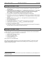
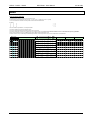
Scuola Universitaria Professionale
della Svizzera Italiana
Dipartimento
Ambiente
Costruzioni e
Design
Istituto
Sostenibilità
Applicata
Ambiente
Costruito
High Accuracy, Customizable
MULTIFUNCTION TESTING DEVICE FOR PHOTOVOLTAIC MODULES
SUPSI-DACD-ISAAC
Via Trevano
CH - 6952 Canobbio
www.isaac.supsi.ch
SUPSI – DACD – ISAAC
MPPT3000 - User Manual
23.05.2007
TABLE OF CONTENTS
Short description ..............................................................................................................................3
Applications ......................................................................................................................................3
Technical specifications ..................................................................................................................4
Performance ......................................................................................................................................4
Box and connections........................................................................................................................5
Front
5
Mounting the MPPT3000
6
Top lateral
7
Bottom lateral
7
Wiring description
8
Choose of the load resistor ...........................................................................................................12
How to chose a load resistor
12
Reachable MPP tracking efficiency vs. output load resistor
12
RS485 network ................................................................................................................................14
Turning on the MPPT3000..............................................................................................................15
Turning off the MPPT3000..............................................................................................................15
Menu.................................................................................................................................................16
Important safety notice
Warning :
In all cases the assembly and installation must be done by qualified technicians, observing the
national requirements and rules stipulated.
Opening the MPPT3000 or using it incorrectly will result in the immediate loss of the warranty,
(unless for upgrades in agreement with manufacturer)
Warranty:
1 year.
Limitation of liability :
ISAAC - SUPSI cannot control the installation, use and maintenance of the MPPT3000.
Thus, we are not responsible for damages, costs or losses resulting from an installation
which is not in accordance with the regulations or inappropriate use or maintenance.
The customer is always responsible for the use of the MPPT3000 and any other related additional
device.
This device has not been designed nor warranted for use in any critical apparatus with potential
risks of serious harm to people or to the environment.
ISAAC - SUPSI reserves the right to modify their products without previous notice.
User Manual - ENG V1.5.doc
2/20
SUPSI – DACD – ISAAC
MPPT3000 - User Manual
23.05.2007
Short description
The MPPT 3000 is a multifunction testing device for photovoltaic modules. A photovoltaic module,
when connected to the MPPT 3000, is set to work in a MPP tracking mode. The MPPT 3000 also
allows a customized I-V Tracer function. It is possible to connect RTD temperature sensors,
pyranometers or other external sensors. The interaction with the MPPT is possible directly using its
LCD and buttons or through a simple graphical user interface. The PV module energy is dissipated
using an external resistor load with heat sink that must be always connected. This device has been
developed for specific PV module testing at the ISAAC - SUPSI laboratory (TISO group).
−
−
−
−
−
−
−
−
−
−
−
−
−
accurate MPP tracking: maximum 0.5 % error on PMPP tracking
wide voltage and current scalable ranges: up to 200V / 20A / max 250W
optoisolated analog auxiliary outputs in order to measure, using an external measurement
system, the PV module working condition and the auxiliary sensors
built-in independent data logging: internal data storage allowing the use of the MPPT as
datalogger
transportable, compact, wide operating ambient temperature range (from -20°C to +40 °C)
galvanically isolated RS-485 interface: dialog between PC master and one or more MPPTs
I-V Tracer : use of the MPPT3000 as settable IV Tracer
simultaneous Im and Vm measurement
non isolated analog output (optional)
run-time selectable ranges (automatic or manual)
possibility to measure, thanks to a built-in micro-converter and independently from data
loggers or external peripherals, the main meteorological parameters (T, G, …) by means of
auxiliary sensors (sensors are not included)
user friendly management software
IP 20 case
Applications
This electrical equipment is extremely useful for anyone who needs to accurately test photovoltaic
modules such school laboratories, module manufacturers or module providers, testing laboratories
and so on.
Typical applications are:
−
−
−
−
−
sc-Si, mc-Si, a-Si, thin-film accurate module testing
I-V characterization
Energy production test and comparison at outdoor real conditions
Meteorological measurements during module test
Comparison of an existing PV plant behaviour with respect to a reference PV module under
test using the MPPT3000.
User Manual - ENG V1.5.doc
3/20
SUPSI – DACD – ISAAC
MPPT3000 - User Manual
23.05.2007
Technical specifications
General
MPPT power supply
Operating ambient temperature
Case protection grade
Load output resistor
Dimensions
Weight
Photovoltaic module values
PMAX in
VMAX @ 250W
ISC MAX
Vm MIN
Measurements
Voltage measurement ranges
Current measurement ranges
°C
Ω
mm
kg
+24VDC / 8 W +/-10%
from -20 to +40
IP20
from 18 to 47 (Load must be always connected !)
194 x 221 x 162 without cableglands nor cables
5
W
V
A
V
250 (continuous);
150
5 / 10 / 20 (depends on the model)
5
V
200 / 100 / 50 / 25
20A Model: 20 / 10 / 5 /2.5
10A Model: 10 / 5 / 2.5 /1.25
5A Model: 5 / 2.5 / 1.25 / 0.625
0.2
A
Accuracy
%
IV Tracer
Scan rate
min
2/3/4/5/6
Points number
128 / 256 / 512
Sweep Time
s
1.0 to 3.0
IV tracing ad hoc available using the MPPT manager software.
MPP Tracker
Full I-V curve search
Types
Fast MPP fine adjust
Control
Power and voltage
Customizable MPP adjust and Vm adjust available.
Auxiliary opto-isolated analog outputs
from 0 to 10 (proportional to the default represented
4 analog outputs (Vm, Im, RTD 1, RTD 2)
VDC
input ranges)
Short circuit protected outputs. High impedance load required.
Auxiliary analog measurement inputs
Auxiliary input 1
RTD only (PT100)
Auxiliary input 2
RTD only (PT100)
Auxiliary input 3
voltage 0…1V max (autorange from 0..10mV to 0..1V)
Galvanically isolated RS-485 port
Bit rate
bps
115200
Data length
bit
8
Stop bit
bit
1
Parity
Even
Flow control
None
Performance
MPP Tracking
Static MPP tracking efficiency
Dynamic MPP tracking efficiency
IV Tracer
IV tracing difference
DC / DC conversion
Typ. Efficiency (Pout/Pin)
%
%
> 99.5
> 98.0
%
±0.2
%
90.0
This performance test has been carried out at specific conditions, please see the specific data-book
for details.
User Manual - ENG V1.5.doc
4/20
SUPSI – DACD – ISAAC
MPPT3000 - User Manual
23.05.2007
Box and connections
Front
Internal Power Supply 1
Internal Power Supply 2
Display 2x16
LCD Back-light
(optional)
Escape
Scroll
Enter
The reset button of the main part (DSP) is placed on the left side of the box.
On the right side, there is the reset button of the auxiliary part (µController). When accessing a reset
button, please use a non conductor stick.
User Manual - ENG V1.5.doc
5/20
SUPSI – DACD – ISAAC
MPPT3000 - User Manual
23.05.2007
Mounting the MPPT3000
The MPPT3000 is provided with integrated heat sink for power dispersion.
In order to get maximum power dispersion the box must be mounted in vertical position or with a
maximum tilt of 30° from vertical position , see also following schematics.
Moreover please allow 1 cm minimum gap from heat sink to mounting wall.
Mounting schematics
The electrical operating temperature of the MPPT goes from -20°C to +70°C but the ambiance
temperature must not exceed 40°C at maximum power (250 W)
User Manual - ENG V1.5.doc
6/20
SUPSI – DACD – ISAAC
MPPT3000 - User Manual
23.05.2007
Top lateral
1
AUX In
RS-485
4
2
AUX Out
3
Power
Supply
5
Bottom lateral
Sense
Load
6
7
PV module
8
User Manual - ENG V1.5.doc
7/20
SUPSI – DACD – ISAAC
MPPT3000 - User Manual
23.05.2007
Wiring description
Connector
1
2
3
4
5
6
7
8
Description
RS-485 line, DB9 male
RS-485 line, DB9 female
Auxiliary analog outputs, DB9 female
Auxiliary input/output of auxiliary part (µController), DB15 male
Power supply of MPPT3000
Input for PV voltage sense measurement
Output power part (to the load resistor)
WARNING! THE LOAD RESISTOR MUST ALWAYS BE CONNECTED
TO THE MPPT3000 ! Using the MPPT3000 without the load resistors
leads to serious damages.
Input for power connection PV module
Connector 1 and 2 :
See chapter RS-485 line.
Connector 3 :
1
2
Output AUX1 (0...10V represents 0...Ufull scale)
Output AUX1 (GND)
3
4
Output AUX2 (0...10V represents 0...Ifull-scale)
Output AUX2 (GND)
5
6
Output AUX3 (0...10V represents 0...AUX_Ch0_full scale)
Output AUX3 (GND)
7
8
Output AUX4 (0...10V represents 0...AUX_Ch1_full scale)
Output AUX4 (GND)
9
not connected
All auxiliary outputs are short circuit protected by means of a 2 kΩ series resistor.
Therefore to measure the output voltage value high impedance input instruments are required.
User Manual - ENG V1.5.doc
8/20
SUPSI – DACD – ISAAC
MPPT3000 - User Manual
23.05.2007
Connector 4 :
Auxiliary measurement part (µC) inputs. Configuration :
_ RTD on AUX IN 1 (AUX_Ch0)
_ RTD on AUX IN 2 (AUX_Ch1)
_ general voltage input on AUX IN 3
The next picture shows how to connect the RTDs and the general purpose voltage input (typically a
pyranometer).
IEXC
1
9
PT100
AUX IN 1
=> AUX OUT 3
& DISPLAY
AUX IN 2
=> AUX OUT 4
& DISPLAY
AUX IN 3
=> DISPLAY
2
10
3
11
PT100
4
12
13
Max 1 VDC
6
AUX IN 3:
The minimum voltage input range is 0..10 mV, the maximum voltage input range is 0..1V. The input
range selection is automatic, just avoid to exceed 1 VDC. The voltage must be always positive
(unipolar). The MPPT itself provides the excitation current for the RTDs.
User Manual - ENG V1.5.doc
9/20
SUPSI – DACD – ISAAC
MPPT3000 - User Manual
23.05.2007
Cable 5 : Power Supply (Input)
1
2
Shield
+24VDC
GND
Internally not connected
Power supply connection :
Check the voltage and the polarity of the power supply.
The voltage and the polarity of the power supply should coincide with that mentioned above.
This connection should be done very carefully observing the polarity, any inappropriate voltage or
polarity can damage the device.
Cable 6 : Voltage Sense (Input)
brown+white
green+yellow
Shield
Sense + PV module
Sense – PV module
Sense – PV module
Voltage sense connection :
Check the voltage and the polarity of the photovoltaic module voltage sense input.
The value of the voltage sense input should in any case NOT exceed 200 VDC (Voc voltage).
This connection should be done properly, observing the polarity, any inappropriate voltage or
polarity can damage the device.
User Manual - ENG V1.5.doc
10/20
SUPSI – DACD – ISAAC
MPPT3000 - User Manual
23.05.2007
Cable 7 : LOAD (Output)
!!!!!! IMPORTANT : THE LOAD MUST ALWAYS BE CONNECTED !!!!!!
1
2+shield
+ Load resistor
- Load resistor
Load connection :
The load MUST always be connected. Using the MPPT3000 without the load resistors
leads to serious damages.
Cable 8 : PV Module power (Input)
1+3
2+yellow/green(4)
Shield
+ PV module
– PV module
– PV module
PV module power connections :
Check the voltage and the polarity of the photovoltaic module.
The voltage of the photovoltaic module should in any case NOT exceed the value of
200 VDC (Voc voltage)
This connection should be done very carefully observing the polarity, any inappropriate voltage or
polarity can damage the device.
User Manual - ENG V1.5.doc
11/20
SUPSI – DACD – ISAAC
MPPT3000 - User Manual
23.05.2007
Choose of the load resistor
How to chose a load resistor
A load resistor must always be connected to the power output of the MPPT3000.
Please chose a resistor value between 18 and 47 Ω in order to :
_ not to exceed Iout (I load) < 3.5 A DC
_ not to exceed Vout (V load) < 108 V DC
according to the power output to disperse.
Example :
Power of module = 250 W
Vmpp max > 5 V ( ex : 17 V)
I mpp max < 20 A (ex : 14.7 A)
R load min = 250 / (3.52) = 20.4 Ω
R load max = (1082) / 250 = 46.6 Ω
Æ thus we choose for example 33 Ω / 250 W (or more powerfull)
Æ check in the two charts below if the value of R load chosen is within
required parameters
Example of resistor to use :
HS series heatsink mount resistors
- Resistance range R005 to 100K Ohms
- To 600W
- Tolerance from 0.5%
- High power to volume ratio
- All welded construction
- Available in Non-Inductive Style (Type N)
- High pulse withstand capability
- Connection variation available
Æ
REMEMBER TO MOUNT LOAD RESISTORS ON A SUITABLE HEAT SINK
Reachable MPP tracking efficiency vs. output load resistor
The maximum power point tracking efficiency depends also on the chosen output load resistor.
As mentioned in the previous sub-chapter, the value of this resistor can vary between 18 and 47 Ω.
The following charts show the MPP tracking efficiency limits vs. output load resistor.
User Manual - ENG V1.5.doc
12/20
SUPSI – DACD – ISAAC
MPPT3000 - User Manual
23.05.2007
Iin = f(Uin) with maximum MPP tracking error percentage limits using 18 Ω output resistor
100
Iin [A]
10
1
Inside the area limited by this lines, the MPPT can
reach the 99.5 % of MPP tracking efficieny (0.5% error).
0.1
1
5V limit
0.5
10
100
1000
Uin [V]
0.5
1
1
1.5
1.5
2
2
250W Limit
Iin = f(Uin) with maximum MPP tracking error percentage limits using 47 Ω output resistor
100
Iin [A]
10
1
Inside the area limited by this lines, the MPPT can
reach the 99.5 % of MPP tracking efficieny (0.5% error).
0.1
1
5V limit
0.5
10
100
1000
Uin [V]
0.5
1
1
1.5
1.5
2
2
250W Limit
It can be seen that most of the working area is inside the by the black lines, which describe the
99.5 % efficiency limits. Only in extreme conditions the efficiency can go slightly below this limit.
However, if the MPPT is used properly, the declared MPP tracking efficiency is respected, as it has
been proved during the MPPT practical test.
User Manual - ENG V1.5.doc
13/20
SUPSI – DACD – ISAAC
MPPT3000 - User Manual
23.05.2007
RS485 network
The MPPT3000 devices can be connected to a master PC through a RS485 network. In this way it
is possible to fully exploit the potential of the device using the specific user friendly management
software. The following scheme shows the correct wiring of the MPPT3000 to the RS485 network.
USB
USB-RS485
Terminator
...
RS485
F
M
F
M
F
M
M
F
M
F
M
F
MPPT 3000
#001
MPPT 3000
#002
MPPT 3000
#NNN
At the end of the RS485 line there must be a terminal resistor, which can varies depending on the
manufacturer of the USB/RS485 adapter and on the cables length. This terminal resistor must be
wired between pin 1 (DATA+) and pin 9 (DATA–) of the DB9 connector.
Pin
1
2
3
4
5
6
7
8
9
DB9 for RS232 pinout1
Data Carrier Detect
RxD
TxD
Data Terminal Ready
Signal Ground
Data Set Ready
Request to Send
Clear to Send
Ring Indicator
DB9 for RS485 pinout2
DATA+
Not connected
Not connected
Not connected
GND
V+
Not connected
Not connected
DATA-
To dialog with one or more MPPTs use only the “MPPT Manager” software. This software allows
the user to manage one or more MPPTs easily.
1
2
Defined by the RS232 standard.
Selected for the MPPT3000 project.
User Manual - ENG V1.5.doc
14/20
SUPSI – DACD – ISAAC
MPPT3000 - User Manual
23.05.2007
Turning on the MPPT3000
1. After wiring the device according to the manual specifications, unplug the PV module from
the MPPT3000.
2. Verify that the full-scale voltage (Ufull scale) and the full-scale current (Ifull scale) are never
exceeded. Every time a PV module is replaced, verify again that the settings for
Ufull scale and Ifull scale are correct. If these requirements are met, go to 7.
3. Turn the device on and wait until the default writing appears on the display3.
4. Set the Ufull scale and Ifull scale in order that the PV module never exceeds the chosen values.
The set-up can be done directly on MPPT3000 or on the graphical interface of the provided
software.
5. Save the settings for Ufull-scale and Ifull-scale. Here again this can de done directly on the
MPPT3000 or by the software.
6. Turn the MPPT3000 off.
7. Turn the device on and wait until the default writing appears on the display4.
8. Verify that the settings for Ufull-scale and Ifull-scale have been loaded correctly.
9. Plug the PV module to the device.
10. At this stage, the MPPT is operating and can communicate with the master PC through the
provided software, performing the requested instructions.
Turning off the MPPT3000
To switch the MPPT off is recommended to use the shutdown command, this command disables
the data logging and prepares the MPPT to be switched off.
1.
2.
3.
4.
Open the MPPT Manager software.
Select the Terminal Folder.
Press the “Shutdown” button.
Wait the MPPT answer.
Now is safe to turn off the MPPT3000.
Note: After the shutdown command is sent, the data logging is disabled. To restore the normal
function mode the MPPT must be restarted either switching off and re-switching on the power
supply or using the reset button.
3
The time necessary for starting (software load to the processor and initialization) may varies slightly but it is
generally about 30 sec.
4
See previous remark.
User Manual - ENG V1.5.doc
15/20
SUPSI – DACD – ISAAC
MPPT3000 - User Manual
23.05.2007
Menu
Introduction about the MPPT Menu
Three alphanumeric characters help the user to browse the menu.
The first character is used to define the level (Level 0 → no sign, Level 1 → single point, Level 2 → 2 points).
The second and the third characters show the position number of the selected lower level.
Examples:
1
2
0
2
2
0
2
2
1
3
0
0
This is an indicative representation, not a full representation.
'
'
"
0
0
0
0
2
2
1
3
Level 0 is the higher level, it represents the main groups.
Level 1 is the level used to browse and select the voices inside a main group.
Level 2 is the lower level, when the user is in this level he can modify the chosen voice. Only the voices that are available in level 2 can be modified directly through the MPPT.
Only the most important voices can be modified directly using the MPPT interface (buttons and scroll).
The other voices are only accessible using the MPPT Manager software, which also provides an easy access to all the features of the MPPT3000.
Menu Levels
0
1
2
Description
1 2 3 4 5 6 7 8 9 10 11 12 13 14 15 16
ESC
Enter
Scroll
Next
Nothing
Next / Previous L0
Next
Nothing
Next / Previous L0
Next
Nothing
Next / Previous L0
Next
Nothing
Next / Previous L0
Next
Nothing
Next / Previous L0
Next
Nothing
Next / Previous L0
Next
Nothing
Next / Previous L0
Next
Nothing
Next / Previous L0
Default
0
0
0
0
0
0
0
0
0
0
0
0
0
1
0
0
2
0
0
3
0
0
4
0
Um, Pm (Normal functioning)
Im, Power part duty cycle
Um, Pm (Power adjustment)
Im, Power part duty cycle
Um, Pm (Voltage adjustment)
Im, Duty Cycle
Um, Pm (MPP full search)
Im, Power part duty cycle
Date, Week day
Hour
E tot
E day
PV module Type
DSP Software version
uController Software version
User Manual - ENG V1.5.doc
x
x
x
x
x
x
x
x
d
h
E
E
M
a
D
x
x
x
x
x
x
x
x
d
h
t
d
o
b
S
u
x
x
x
x
x
x
x
x
.
:
x
x
d
c
P
C
.
.
.
.
.
.
.
.
m
m
x
x
u
d
x
x
x
x
x
x
x
x
m
m
x
x
l
e
S
S
x
x
x
x
x
x
x
x
.
:
x
x
e
f
W
W
y
s
x
x
g
V
A
V
A
V
A
V
A
y
s
x
x
T
h
x
x
→ x
x
← x
x
# x
# x
A
x
x
x
x
x
x
x
x
b
x
x
y
i
a
a
x . x
W h
x . x
W h
e
k l m n o p
c d e f g h
c d e f g h
x
x
p
j
b
b
16/20
x
x
x
x
x
x
x
x
c
.
.
.
.
.
.
.
.
x
x
x
x
x
x
x
x
W
%
W
%
W
%
W
%
SUPSI – DACD – ISAAC
MPPT3000 - User Manual
23.05.2007
Low Refresh Info
1
99
0
1
0
0
1
0
1
1
1
0
1
2
0
1
3
0
1
4
0
1
5
0
1
6
0
1
7
0
1
8
0
1
9
0
1
10
0
1
11
0
1
12
0
1
13
0
1
14
0
1
15
0
1
15
1
1
16
0
1
16
1
1
17
0
1
17
1
1
18
0
1
19
0
1
20
0
1
21
0
1
22
0
RS485 network ID
PV module manufacturer
PV module type
PV module serial number
PV module database ID
PV module ID code
PV module position
Auxiliary output 2 external datalogger
associated channel
Auxiliary output 3 external datalogger
associated channel
PV module MPP power @ STC.
PV module MPP current @ STC.
L o w
R e f r e s h
I n f o
( S e t u p 1
M P P T
I D
S e
t
M P P T
M
a
M
a
S
a
D
a
b
o
b
e
b
a
n
c
d
c
r
c
t
M
a
P
a
C
o
b
o
b
h
d
c d
s i
c d
u
d
u
d
i
d
a
C h
P m
@
I m
@
V m
PV module short circuit current @ STC
I
PV module open circuit voltage @ STC
V o c
PV module fill factor.
F F
MPPT current mesuring shunt resistor.
R s h u n
s
@
c
I D
f a c t u r e r
e f g h i j k l
l e
T y p e
e f g h i j k l
a l
N r
e f g h i j k l
b
M o d
I D
x x
I D
C o d e
e f g h i j k l
t i o n
e f g h i j k l
A u x
2
x x
A u x
3
x x
S T C
x x x .
S T C
x x x .
S T C
x x x .
@
S T C
x x x .
@
S T C
x x x .
PV module MPP voltage @ STC.
x
x
x
.
S e
t
V
R a n g e
Default current range
(Auxiliary output 1 refers to this value)
I
S
R s h u n
t
V
PV module cell area
C
PV module area
M
PV module cells in serie
C
PV module cells in parallel
C e
l
l
Output resistor
R o u
t
User Manual - ENG V1.5.doc
s
m
m
x
m
m
x
x
x
x
x
x
x
x
i
n
x
t
x
R a n g
x
R a n g e
x x x
e t
I
R a n g
x x x
e l l
A r e a
x x x .
o d u l e
A r e
x x x .
e l l s
i n
s
S e
m
t
x
Default voltage range
(Auxiliary output 0 refers to this value)
0 1
)
x
x
x x
e
x x
.
.
. x x
e
. x x
x
a
x
e
x
p a
x
x
x
r
x
r
x
x
x
x
17/20
'
x
"
x
'
n
'
n
'
n
'
x
'
n
'
n
'
x
'
x
'
x
'
x
'
x
'
x
'
x
'
x
'
0
x
0
x
0
o
0
o
0
o
0
x
0
o
0
o
0
x
0
x
0
1
1
1
1
1
1
m
" 0
m
' 1
x
" 0
x
' 1
x
" 0
x
' 1
c m
' 1
m
' 2
x x
' 2
x x
' 2
x
0
x
1
x
1
p
2
p
3
p
4
x
5
p
6
p
7
x
8
x
9
W
0
A
1
V
2
A
3
V
4
%
5
Ω
1
Ω
6
V
1
V
7
A
1
A
8
2
9
2
0
x
1
x
2
Ω
Level UP
Level DOWN
Next / Previous L0
Level UP
Level DOWN
Next / Previous L1
Level UP
(don't load in RAM)
Enter
Change state
Level UP
Nothing
Next / Previous L1
Level UP
Nothing
Next / Previous L1
Level UP
Nothing
Next / Previous L1
Level UP
Nothing
Next / Previous L1
Level UP
Nothing
Next / Previous L1
Level UP
Nothing
Next / Previous L1
Level UP
Nothing
Next / Previous L1
Level UP
Nothing
Next / Previous L1
Level UP
Nothing
Next / Previous L1
Level UP
Nothing
Next / Previous L1
Level UP
Nothing
Next / Previous L1
Level UP
Nothing
Next / Previous L1
Level UP
Nothing
Next / Previous L1
Level UP
Nothing
Next / Previous L1
Level UP
Level DOWN
Next / Previous L1
Level UP
(don't load in RAM)
Enter
Change state
Level UP
Level DOWN
Next / Previous L1
Level UP
(don't load in RAM)
Enter
Change state
Level UP
Level DOWN
Next / Previous L1
Level UP
(don't load in RAM)
Enter
Change state
Level UP
Nothing
Next / Previous L1
Level UP
Nothing
Next / Previous L1
Level UP
Nothing
Next / Previous L1
Level UP
Nothing
Next / Previous L1
Level UP
Level DOWN
Next / Previous L1
SUPSI – DACD – ISAAC
MPPT3000 - User Manual
23.05.2007
Setup
2
99
0
2
0
0
2
0
1
2
1
0
2
1
1
2
2
0
2
2
1
2
3
0
2
3
1
2
4
0
2
4
1
2
5
0
2
5
1
2
6
0
2
6
1
2
7
0
2
7
1
2
8
0
2
8
1
2
9
0
2
9
1
2
10
0
2
10
1
2
11
0
2
11
1
2
12
0
2
12
1
2
13
0
2
14
0
2
15
0
2
16
0
2
16
1
2
17
0
2
18
0
2
18
1
PWM duty cycle manual setting.
(use this only for debug purposes)
MPP full search.
H i g h
R e f r e s h
I n f o
( S e t u p 2
M a n u a l
P W M
x x x
x x x
M P P
S e
MPP full search type
MPP full search scan rate
MPP full search sweep time
MPP full fearch dead time
MPP adjustement state (ON/OFF)
.
.
t
x x x V
x x x A
F S
M P P
M P P
F S
S
T
M
R
S
S
M
S
S
S
M
D
S
D
M
M P P
e
y
P
a
e
c
P
w
e
w
P
e
e
e
P
t
p
P
t
t
a
P
e
t
e
P
a
t
a
P
S e
t
MPP adjustement start window
M P P
MPP adjustement end window
S
S
M
Voltage adjustement state (ON/OFF)
S
E
V
x
x
x
x
F S
F S
e
F S
S c a n
e
n
e
e
d
d
x
M P
R
F S
p
M P
p
F S
T
M P
T
A d
P
a
t
t
T
P
T
F S
e
x
.
x
x
.
.
x
.
x
j
A d
S
x
A
x
E
x
A
x
x
x
x
x
A d
x
d
x
x
d
x
j
W
x
j
x
W
x
j
x
i n
x x
x x
i n
x x
x
Voltage adjustement end window
S
S
V
Automatic IV Tracer state (ON/OFF)
S
E
I
W
x
e t
V m
A d j
W i n
x
m
A d j
E
W
x
e t
V m
A d j
W i n
x
V
T r
S t a t
S
S
I
R
I
e t
I V
T r
t a t e
V
T r
S c a n
a t e
x x
h
V
T r
P o i n t s
I
V
Main datalogging scan rate
Autorange state (ON/OFF)
Restore default setup
User Manual - ENG V1.5.doc
T
x
j
V m
Ad hoc IV Tracer points number
(Automatic IV Tracer always has 256 pts)
IV Tracer seweep time
j
x
x
x x
F S
x x
P
A d
A d
x
F S
M P P
V m
x
Voltage adjustement start window
Automatic IV Tracer Scan Rate
.
.
T y p e
j
x
e t
M P P
W i n
x
P P
A d j
x
e t
M P P
W i n
x
m
A d j
S e
x
x
0 2
)
S
i n
x x x
x x x
i n
x x x
x x
e
x
x
r
D
R
S
L
A
S w e e p
T
x x .
a t a
L o g g i n g
a t e
x
e t
D a t a
o g g i n g
R a t e x
u t o r a n g e
R
D
P
t
e s t o r e
e f a u l t
S e
r e s s
E n t e
o
R e s t o r e
18/20
t
r
u p
S e
'
0 0
x
x
'
A
"
A
'
W
%
1
C
1
C
2
x
1
x
3
s
1
s
4
s
1
s
5
s
1
s
6
C
1
C
7
x
1
x
8
x
1
x
9
C
1
C
0
x
1
x
1
x
1
x
2
C
1
C
3
m
4
x
5
s
6
m
1
m
7
C
0
x
x
0
B
0
B
0
x
" 0
x
' 0
x
" 0
x
' 0
x
" 0
x
' 0
x
" 0
x
' 0
A B
" 0
A B
' 0
x x
" 0
x x
' 0
x x
" 0
x x
' 0
A B
" 0
A B
' 1
x x
" 0
x x
' 1
x x
" 0
x x
' 1
A B
" 0
A B
' 1
x
' 1
x x
' 1
x
' 1
x
" 0
x
' 1
A B
' 2
?
" 0
t u
1
p
Level UP
Level DOWN
Next / Previous L0
Level UP
Level DOWN
Next / Previous L1
Level UP
Change Quad
Encoder Step
Change Duty Cycle B
Level UP
Level DOWN
Next / Previous L1
Level UP
(don't load)
Load into RAM
Change state
Level UP
Level DOWN
Next / Previous L1
Level UP
(don't load)
Enter
Load into RAM
Change state
Next / Previous L1
Level UP
Level DOWN
Level UP
(don't load)
Enter
Load into RAM
Change state
Level UP
Level DOWN
Next / Previous L1
Level UP
(don't load)
Enter
Load into RAM
Change state
Level UP
Level DOWN
Next / Previous L1
Level UP
(don't load)
Enter
Load into RAM
Change state
Level UP
Level DOWN
Next / Previous L1
Level UP
(don't load)
Load into RAM
Change state
Level UP
Level DOWN
Next / Previous L1
Level UP
(don't load)
Load into RAM
Change state
Level UP
Level DOWN
Next / Previous L1
Level UP
(don't load)
Load into RAM
Change state
Level UP
Level DOWN
Next / Previous L1
Level UP
(don't load)
Load into RAM
Change state
Level UP
Level DOWN
Next / Previous L1
Level UP
(don't load)
Load into RAM
Change state
Level UP
Level DOWN
Next / Previous L1
Level UP
(don't load)
Load into RAM
Change state
Level UP
Level DOWN
Next / Previous L1
Level UP
(don't load)
Load into RAM
Change state
Level UP
Nothing
Next / Previous L1
Level UP
Nothing
Next / Previous L1
Level UP
Nothing
Next / Previous L1
Level UP
Level DOWN
Next / Previous L1
Level UP
(don't load)
Load into RAM
Change state
Level UP
Level DOWN
Next / Previous L1
Level UP
Level DOWN
Next / Previous L1
Level UP
(don't restore)
Restore default LRI
into RAM
Nothing
SUPSI – DACD – ISAAC
MPPT3000 - User Manual
23.05.2007
Save/Load
3
99
0
3
0
0
3
0
1
3
1
0
3
1
1
3
2
0
3
2
1
3
3
3
3
0
Save Low Refresh Info (Setup1) into
MPPT flash memory
Load Low Refresh Info (Setup1) from
flash memory to MPPT RAM
Save High Refresh Info (Setup2) into
MPPT flash memory
Load High Refresh Info (Setup2) from
flash memory to MPPT RAM
1
S
D
S
i
P
t
L
i
P
t
S
i
P
t
L
i
P
t
a
S
a
n
r
o
o
n
r
o
a
n
r
o
o
n
r
o
v
P
v
t
e
o
r
R
l
E
e
R
S
E
d
e
l
E
e
e
S
E
d
a d
t
I
a s h
n t e
L R
I
P
R
n t e
L R
t u p
a s h
n t e
S e
t u p
P
R
n t e
S e
u C o n v e
r
t
e
r
x
° C x
x V x
x
x
a
t
e
v
t
e
a
t
e
e
e
o
s
S
d
o
s
L
e
o
s
S
d
o
s
L
/ L
P a
L
F
s
a v
L
D
s
o a
S
F
s
a v
S
D
s
o a
0 3
' 0 0
A b c
" 0 1
?
r
I
' 0 1
A M ? A b c
r
" 0 1
I
' 0 2
?
r
" 0 1
t u p
' 0 3
A M ? A b c
r
" 0 1
t u p
Level UP
Level DOWN
Next / Previous L0
Level UP
Level DOWN
Next / Previous L1
Level UP
(don't save)
Enter
(Save)
Nothing
Level UP
Level DOWN
Next / Previous L1
Level UP
(don't load)
Enter
(Load)
Nothing
Level UP
Level DOWN
Next / Previous L1
Level UP
(don't save)
Enter
(Save)
Nothing
Level UP
Level DOWN
Next / Previous L1
Level UP
(don't load)
Enter
(Load)
Nothing
Level UP
Level DOWN
Next / Previous L0
Level UP
Nothing
Next / Previous L1
uConverter
4
4
99
0
0
0
T ch0, T ch1
U ch3, T internal sensor
User Manual - ENG V1.5.doc
x
x
x
.
.
x
x
x
x
19/20
0 4
x
x
.
.
x
x
x
x
° C
° C
SUPSI – DACD – ISAAC
MPPT3000 - User Manual
ISAAC , SUPSI - DACD
CP 105
6952 Canobbio
SWITZERLAND
Tel:
Fax:
E-mail:
Web:
+41 58 666 63 51
+41 58 666 63 49
[email protected]
www.isaac.supsi.ch
User Manual - ENG V1.5.doc
20/20
23.05.2007