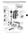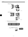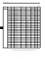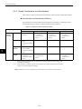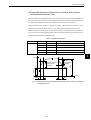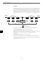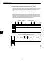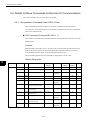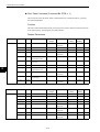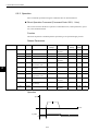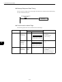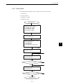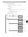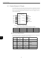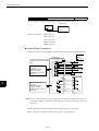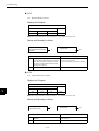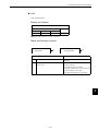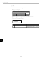
1
Cat. No. I538-E1-01 USER’S MANUAL OMNUC W SERIES Model R88A-NCW152-DRT DeviceNet Option Unit Thank you for choosing this OMNUC W-series DeviceNet Option Unit. Proper use and handling of the product will ensure proper product performance, will length product life, and may prevent possible accidents. Please read this manual thoroughly and handle and operate the product with care. General Instructions 1. This manual describes the functions of the product and relations with other products. You should assume that anything not described in this manual is not possible. 2. Although care has been given in documenting the product, please contact your OMRON representative if you have any suggestions on improving this manual. 3. The product contains dangerous high voltages inside. Turn OFF the power and wait for at least five minutes to allow power to discharge before handling or working with the product. Never attempt to disassemble the product. 4. We recommend that you add the following precautions to any instruction manuals you prepare for the system into which the product is being installed. S Precautions on the dangers of high-voltage equipment. S Precautions on touching the terminals of the product even after power has been turned OFF. (These terminals are live even with the power turned OFF.) 5. Specifications and functions may be changed without notice in order to improve product performance. 6. Positive and negative rotation of AC Servomotors described in this manual are defined as looking at the end of the output shaft of the motor as follows: counterclockwise rotation is positive and clockwise rotation is negative. 7. Do not perform withstand-voltage or other megameter tests on the product. Doing so may damage internal components. 8. Servomotors and Servo Drivers have a finite service life. Be sure to keep replacement products on hand and to consider the operating environment and other conditions affecting the service life. 9. The OMNUC W Series can control both incremental and absolute encoders. Differences in functions or specifications according to the encoder type are indicated in this manual. Be sure to check the model that is being used, and follow the relevant specifications. S Servomotors with incremental encoders: R88M-WjH-j/-WjL-j S Servomotors with absolute encoders: R88M-WjT-j/-WjS-j Notice Before using the product under the following conditions, consult your OMRON representatives, make sure that the ratings and performance characteristics of the product are good enough for the systems, machines, or equipment, and be sure to provide the systems, machines, or equipment with double safety mechanisms. 1. Conditions not described in the manual. 2. The application of the product to nuclear control systems, railroad systems, aviation systems, vehicles, combustion systems, medical equipment, amusement machines, or safety equipment. 3. The application of the product to systems, machines, or equipment that may have a serious influence on human life and property if they are used improperly. Items to Check After Unpacking Check the following items after removing the product from the package: S Has the correct product been delivered (i.e., the correct model number and specifications)? S Has the product been damaged in shipping? S Are any screws or bolts loose? The following are included with the DeviceNet Unit. Safety Precautions 1 Communications Connector (From Phoenix Contact: MSTB 2.5/5–STF–5.08AUM) 1 Ground screws (pan head; M3 x 10, M4 x 8, and M4 x 10)* 3 * The ground screws that are used depend on the model of the Servo Driver to which the DeviceNet Unit is mounted. USER’S MANUAL OMNUC W SERIES Model R88A-NCW152-DRT DeviceNet Option Unit Notice: OMRON products are manufactured for use according to proper procedures by a qualified operator and only for the purposes described in this manual. The following conventions are used to indicate and classify precautions in this manual. Always heed the information provided with them. Failure to heed precautions can result in injury to people or damage to property. Indicates an imminently hazardous situation which, if not avoided, will result in death or serious injury. ! DANGER ! WARNING Indicates a potentially hazardous situation which, if not avoided, could result in death or serious injury. ! Caution Indicates a potentially hazardous situation which, if not avoided, may result in minor or moderate injury, or property damage. OMRON Product References All OMRON products are capitalized in this manual. The word “Unit” is also capitalized when it refers to an OMRON product, regardless of whether or not it appears in the proper name of the product. The abbreviation “Ch,” which appears in some displays and on some OMRON products, often means “word” and is abbreviated “Wd” in documentation in this sense. The abbreviation “PC” means Programmable Controller and is not used as an abbreviation for anything else. Visual Aids The following headings appear in the left column of the manual to help you locate different types of information. Note Indicates information of particular interest for efficient and convenient operation of the product. OMRON, 2001 All rights reserved. No part of this publication may be reproduced, stored in a retrieval system, or transmitted, in any form, or by any means, mechanical, electronic, photocopying, recording, or otherwise, without the prior written permission of OMRON. No patent liability is assumed with respect to the use of the information contained herein. Moreover, because OMRON is constantly striving to improve its high–quality products, the information contained in this manual is subject to change without notice. Every precaution has been taken in the preparation of this manual. Nevertheless, OMRON assumes no responsibility for deviations or omissions. Neither is any liability assumed for damages resulting from the use of the information contained in this publication. 1 General Warnings Observe the following warnings when using the DeviceNet Unit and all peripheral devices. This manual may include illustrations of the product with protective covers removed in order to describe the components of the product in detail. Make sure that these protective covers are on the product before use. Consult your OMRON representative when using the product after a long period of storage. ! Always connect the frame ground terminals of the Servo Driver and the Servomotor to a WARNING class–3 ground (to 100 Ω or less). Not connecting to a class-3 ground may result in electric shock. ! WARNING Do not touch the inside of the Servo Driver. Doing so may result in electric shock. ! WARNING while the power is being supplied. Doing so may result in electric shock. ! WARNING nel. Not doing so may result in electric shock or injury. ! WARNING power supply. Doing so may result in electric shock. ! WARNING result in electric shock, stopping operation of the product, or burning. ! WARNING Do not touch the rotating parts of the Servomotor in operation. Doing so may result in injury. ! WARNING Do not modify the product. Doing so may result in injury or damage to the product. Do not remove the front cover, terminal covers, cables, Parameter Units, or optional items Installation, operation, maintenance, or inspection must be performed by authorized person- Wiring or inspection must not be performed for at least five minutes after turning OFF the Do not damage, press, or put excessive stress or heavy objects on the cables. Doing so may ! Caution Use the Servomotors and Servo Drivers in a specified combination. Using them incorrectly may result in fire or damage to the product. ! Caution Do not store or install the product in the following places. Doing so may result in fire, electric shock, or damage to the product. • DeviceNet is a registered trademark of the ODVA (Open DeviceNet Vendors Association, Inc.). • Locations subject to direct sunlight. • Locations subject to temperatures or humidity outside the range specified in the specifications. • Locations subject to condensation as the result of severe changes in temperature. • Locations subject to corrosive or flammable gases. • Locations subject to dust (especially iron dust) or salts. • Locations subject to shock or vibration. • Locations subject to exposure to water, oil, or chemicals. ! Caution Do not touch the Servo Driver radiator, Regeneration Resistor, or Servomotor while the power is being supplied or soon after the power is turned OFF. Doing so may result in a skin burn due to the hot surface. 2 Storage and Transportation Precautions ! Caution Do not hold the product by the cables or motor shaft while transporting it. Doing so may result in injury or malfunction. ! Caution Do not place any load exceeding the figure indicated on the product. Doing so may result in injury or malfunction. ! Caution Use the motor eye–bolts only for transporting the Motor. Using them for transporting the machinery may result in injury or malfunction. Installation and Wiring Precautions ! Caution Do not step on or place a heavy object on the product. Doing so may result in injury. ! Caution Do not cover the inlet or outlet ports and prevent any foreign objects from entering the product. Doing so may result in fire. ! Caution Be sure to install the product in the correct direction. Not doing so may result in malfunction. ! Caution Provide the specified clearances between the Servo Driver and the control panel or with other devices. Not doing so may result in fire or malfunction. ! Caution Do not apply any strong impact. Doing so may result in malfunction. ! Caution Be sure to wire correctly and securely. Not doing so may result in motor runaway, injury, or malfunction. ! Caution Be sure to install the Unit correctly and securely. Not doing so may result in motor runaway, injury, or malfunction. ! Caution Be sure that all the mounting screws, terminal screws, and cable connector screws are tightened to the torque specified in the relevant manuals. Incorrect tightening torque may result in malfunction. ! Caution Use crimp terminals for wiring. Do not connect bare stranded wires directly to terminals. Connection of bare stranded wires may result in fire. ! Caution Always use the power supply voltage specified in the User’s Manual. An incorrect voltage may result in burning. ! Caution Take appropriate measures to ensure that the specified power with the rated voltage and frequency is supplied. Be particularly careful in places where the power supply is unstable. An incorrect power supply may result in damage to the product. ! Caution Install external breakers and take other safety measures against short–circuiting in external wiring. Insufficient safety measures against short–circuiting may result in fire. ! Caution Provide an appropriate stopping device on the machine side to secure safety. (A holding brake is not a stopping device for securing safety.) Not doing so may result in injury. ! Caution Provide an external emergency stopping device that allows an instantaneous stop of operation and power interruption. Not doing so may result in injury. 3 ! Caution Take appropriate and sufficient countermeasures when installing systems in the following locations. Not doing so may result in damage to the product. • Locations subject to static electricity or other forms of noise. • Locations subject to strong electromagnetic fields and magnetic fields. • Locations subject to possible exposure to radioactivity. • Locations close to power supplies. ! Caution Do not reverse the polarity of the battery when connecting it. Reversing the polarity may damage the battery or cause it to explode. ! Caution Before touching a Unit, be sure to first touch a grounded metallic object in order to discharge any static build–up. Not doing so may result in malfunction or damage. Operation and Adjustment Precautions ! Caution Confirm that no adverse effects will occur in the system before performing the test operation. Not doing so may result in damage to the product. ! Caution Check the newly set parameters and switches for proper execution before actually running them. Not doing so may result in damage to the product. ! Caution Do not make any extreme adjustments or setting changes. Doing so may result in unstable operation and injury. ! Caution Separate the Servomotor from the machine, check for proper operation, and then connect to the machine. Not doing so may cause injury. ! Caution When an alarm occurs, remove the cause, reset the alarm after confirming safety, and then resume operation. Not doing so may result in injury. ! Caution ! Caution ! Caution ! Caution ! Caution Do not come close to the machine immediately after resetting momentary power interruption to avoid an unexpected restart. (Take appropriate measures to secure safety against an unexpected restart.) Doing so may result in injury. Do not use the built–in brake of the Servomotor for ordinary braking. Doing so may result in malfunction. When using the DeviceNet Unit in a Programmable Controller system, execute online edit only after confirming that no adverse effects will be caused by extending the cycle time. Otherwise, the input signals may not be readable. When using the DeviceNet Unit in a Programmable Controller system, confirm safety at the destination node before transferring parameters or other data to another node or changing output signals. Doing either of these without confirming safety may result in injury. Confirm that no adverse effect will occur in the system before attempting any of the following. Not doing so may result in an unexpected operation or damage to the product. • Changing the present values or set values. • Changing the parameters. ! Caution Do not turn OFF the power supply to the Unit while data is being transferred. Doing so may result in malfunction or damage to the product. 4 Maintenance and Inspection Precautions ! Do not attempt to disassemble, repair, or modify any Units. Any attempt to do so may result WARNING in malfunction, fire, electric shock, or injury. ! Caution Resume operation only after transferring to the new Unit the contents of the data required for operation. Not doing so may result in an unexpected operation or damage to the product. 5 Overview ! About this Manual This manual provides the following information for the OMNUC W-series R88M-W", R88D-WT" AC Servomotors/Servo Drivers with an R88A-NCW152-DRT DeviceNet Option Unit (hereinafter called the DeviceNet Unit) mounted. • Procedures for installing and wiring the DeviceNet Unit • Specifications and methods for DeviceNet communications • Procedures for setting user parameters • Information on the Setup Tool • Troubleshooting procedures Related Manuals ! Refer to the following manuals as required. ! Read this manual carefully to ensure the proper use of W-series Servo Driver. Also, keep this manual in a safe place so that it can be referred to whenever necessary. Manual Name Manual No. Contents OMNUC W-series I531-E1-" AC Servomotors/Servo Drivers User’s Manual Provides the detailed information on models and functions of OMNUC W-Series Servo Drivers. DeviceNet User’s Manual Provides the overview of DeviceNet and installation. W267-E1-" Registered Trademark DeviceNet is a registered trademark of the ODVA (Open DeviceNet Vendor Association, Inc.). 6 Contents 1 Features and System Configuration 1.1 Features - - - - - - - - - - - - - - - - - - - - - - - - - - - - - - - - - - - - - 1-2 1.2 System Configuration - - - - - - - - - - - - - - - - - - - - - - - - - - - - 1-4 1.3 Basic Functions and Function Outlines - - - - - - - - - - - - - - - - 1-5 1.4 Specifications- - - - - - - - - - - - - - - - - - - - - - - - - - - - - - - - - - 1-6 1.4.1 1.4.2 1.4.3 1.4.4 General Specifications - - - - - - - - - - - - - - - - - - - - - - - - - - - - - - - - - -1-6 Performance Specifications - - - - - - - - - - - - - - - - - - - - - - - - - - - - - - -1-7 I/O Specifications - - - - - - - - - - - - - - - - - - - - - - - - - - - - - - - - - - - - - -1-7 DeviceNet Communications Specifications - - - - - - - - - - - - - - - - - - - -1-8 2 Outline Drawings and Nomenclature 2.1 Outline Drawings - - - - - - - - - - - - - - - - - - - - - - - - - - - - - - - 2-2 2.2 Checking Products on Delivery - - - - - - - - - - - - - - - - - - - - - 2-4 2.3 Product Nomenclature - - - - - - - - - - - - - - - - - - - - - - - - - - - 2-5 2.4 Mounting the DeviceNet Unit - - - - - - - - - - - - - - - - - - - - - - - 2-6 3 Installation 3.1 Storage Conditions - - - - - - - - - - - - - - - - - - - - - - - - - - - - - - 3-2 3.2 Installation Site- - - - - - - - - - - - - - - - - - - - - - - - - - - - - - - - - 3-2 3.3 Orientation- - - - - - - - - - - - - - - - - - - - - - - - - - - - - - - - - - - - 3-3 3.4 Installation - - - - - - - - - - - - - - - - - - - - - - - - - - - - - - - - - - - - 3-4 4 Connectors 4.1 Connecting to Peripheral Devices - - - - - - - - - - - - - - - - - - - 4-2 4.1.1 Single-phase (100 V or 200 V) Main Circuit Specifications - - - - - - - - -4-3 4.1.2 Three-phase, 200-V Main Circuit Specifications- - - - - - - - - - - - - - - - -4-4 4.1.3 Three-phase, 400-V Main Circuit Specifications- - - - - - - - - - - - - - - - -4-5 4.2 Internal Block Diagrams - - - - - - - - - - - - - - - - - - - - - - - - - - 4-6 4.3 Servo Driver I/O Signals - - - - - - - - - - - - - - - - - - - - - - - - - - 4-7 4.3.1 4.3.2 4.3.3 4.3.4 Connection Example of I/O Signal Connector (CN1) - - - - - - - - - - - - -4-7 I/O Signals Connector (CN1) - - - - - - - - - - - - - - - - - - - - - - - - - - - - - -4-8 I/O Signal Names and Functions - - - - - - - - - - - - - - - - - - - - - - - - - - -4-9 Interface Circuits - - - - - - - - - - - - - - - - - - - - - - - - - - - - - - - - - - - - - 4-10 4.4 I/O Signal Connections for DeviceNet Units (CN4)- - - - - - - 4-12 4.4.1 4.4.2 4.4.3 4.4.4 CN4 Connection Example - - - - - - - - - - - - - - - - - - - - - - - - - - - - - - - 4-12 Connection Terminal Layout - - - - - - - - - - - - - - - - - - - - - - - - - - - - - 4-12 I/O Signal Interface Circuits - - - - - - - - - - - - - - - - - - - - - - - - - - - - - - 4-13 Fully-closed Encoder Connection Example - - - - - - - - - - - - - - - - - - - 4-14 7 4.5 Connection and Wiring of the DeviceNet Communications Connector - - - - - - - - - - - 4-15 4.5.1 Connector Specifications - - - - - - - - - - - - - - - - - - - - - - - - - - - - - - - 4-15 4.5.2 DeviceNet Communications Connection Example- - - - - - - - - - - - - - 4-17 4.5.3 DeviceNet Network Configuration Restrictions - - - - - - - - - - - - - - - - 4-19 5 Parameter Settings 5.1 Parameters - - - - - - - - - - - - - - - - - - - - - - - - - - - - - - - - - - - 5-2 5.1.1 5.1.2 5.1.3 5.1.4 Outline of Parameters - - - - - - - - - - - - - - - - - - - - - - - - - - - - - - - - - - 5-2 Parameter Types - - - - - - - - - - - - - - - - - - - - - - - - - - - - - - - - - - - - - - 5-2 Editing Parameters - - - - - - - - - - - - - - - - - - - - - - - - - - - - - - - - - - - - 5-3 Effective Timing - - - - - - - - - - - - - - - - - - - - - - - - - - - - - - - - - - - - - - - 5-3 5.2 Parameter Tables - - - - - - - - - - - - - - - - - - - - - - - - - - - - - - - 5-4 5.2.1 5.2.2 5.2.3 5.2.4 5.2.5 5.2.6 5.2.7 5.2.8 Unit Parameters- - - - - - - - - - - - - - - - - - - - - - - - - - - - - - - - - - - - - - - 5-4 Origin Search Parameters - - - - - - - - - - - - - - - - - - - - - - - - - - - - - - - 5-4 Machine System and Peripheral Device Parameters - - - - - - - - - - - - - 5-5 Speed, Acceleration, and Deceleration Parameters- - - - - - - - - - - - - - 5-6 Positioning Parameters - - - - - - - - - - - - - - - - - - - - - - - - - - - - - - - - - 5-7 Multi-speed Positioning Parameters- - - - - - - - - - - - - - - - - - - - - - - - - 5-7 Notch Output Parameters - - - - - - - - - - - - - - - - - - - - - - - - - - - - - - - - 5-9 Point Table Parameter - - - - - - - - - - - - - - - - - - - - - - - - - - - - - - - - - - 5-9 5.3 Parameter Details - - - - - - - - - - - - - - - - - - - - - - - - - - - - - 5-10 5.3.1 5.3.2 5.3.3 5.3.4 5.3.5 5.3.6 5.3.7 5.3.8 Unit Parameters- - - - - - - - - - - - - - - - - - - - - - - - - - - - - - - - - - - - - Origin Search Parameters - - - - - - - - - - - - - - - - - - - - - - - - - - - - - Machine System and Peripheral Devices - - - - - - - - - - - - - - - - - - - Speed, Acceleration, and Deceleration - - - - - - - - - - - - - - - - - - - - Positioning - - - - - - - - - - - - - - - - - - - - - - - - - - - - - - - - - - - - - - - - Point Table - - - - - - - - - - - - - - - - - - - - - - - - - - - - - - - - - - - - - - - - Multi-speed Positioning - - - - - - - - - - - - - - - - - - - - - - - - - - - - - - - Notch Signal Output Positioning - - - - - - - - - - - - - - - - - - - - - - - - - - 5-10 5-13 5-22 5-26 5-39 5-41 5-41 5-42 6 DeviceNet Communications 6.1 Control Configuration - - - - - - - - - - - - - - - - - - - - - - - - - - - - 6-3 6.2 DeviceNet Switch Settings and Display - - - - - - - - - - - - - - - 6-4 6.2.1 Rotary Switch Settings for Setting Node Address - - - - - - - - - - - - - - - 6-4 6.2.2 Rotary Switch Settings for Setting Baud Rate - - - - - - - - - - - - - - - - - - 6-5 6.2.3 LED Indicators- - - - - - - - - - - - - - - - - - - - - - - - - - - - - - - - - - - - - - - - 6-5 6.3 Precautions for Communications Line Design - - - - - - - - - - - 6-6 6.3.1 Providing the Communications Power Supply- - - - - - - - - - - - - - - - - - 6-6 6.3.2 Communications Line Noise Precautions - - - - - - - - - - - - - - - - - - - - 6-16 6.4 Overview of Remote I/O and Explicit Message Communications - - - - - - - - - - - - - - - - - 6-20 6.4.1 Remote I/O Communications - - - - - - - - - - - - - - - - - - - - - - - - - - - - 6-20 6.4.2 Explicit Message Communications - - - - - - - - - - - - - - - - - - - - - - - - 6-20 6.5 Remote I/O Communications- - - - - - - - - - - - - - - - - - - - - - 6-21 6.5.1 6.5.2 6.5.3 6.5.4 Basic Block - - - - - - - - - - - - - - - - - - - - - - - - - - - - - - - - - - - - - - - - General Command Bits and Status - - - - - - - - - - - - - - - - - - - - - - - Move Commands for Remote I/O Communications - - - - - - - - - - - - Set/Read Commands for Remote I/O Communications - - - - - - - - - 8 6-21 6-22 6-26 6-34 6.6 Details on Move Commands for Remote I/O Communications - - - - - - - - - - - - - - - - - - - 6-42 6.6.1 No-operation (Command Code: 0000, 0 Hex)- - - - - - - - - - - - - - - - - 6-42 6.6.2 Operation- - - - - - - - - - - - - - - - - - - - - - - - - - - - - - - - - - - - - - - - - - - 6-52 6.7 Command Method Using the Remote I/O Communications - - - - - - - - - - - - - - - - - - - - - - - - - - - - - - 6-60 6.7.1 Basic Operation - - - - - - - - - - - - - - - - - - - - - - - - - - - - - - - - - - - - - - 6-60 6.7.2 Command Method - - - - - - - - - - - - - - - - - - - - - - - - - - - - - - - - - - - - 6-60 6.8 Communications Using Explicit Messages - - - - - - - - - - - - 6-65 6.8.1 Explicit Messages Overview - - - - - - - - - - - - - - - - - - - - - - - - - - - - - 6-65 6.8.2 Command/Response Blocks - - - - - - - - - - - - - - - - - - - - - - - - - - - - - 6-66 6.8.3 Sending Explicit Messages Using the CMND Instruction - - - - - - - - - 6-68 6.9 Tracing Data - - - - - - - - - - - - - - - - - - - - - - - - - - - - - - - - - 6-71 6.9.1 Trace Parameters - - - - - - - - - - - - - - - - - - - - - - - - - - - - - - - - - - - - - 6-71 6.9.2 Reading Trace Data - - - - - - - - - - - - - - - - - - - - - - - - - - - - - - - - - - - 6-74 6.9.3 Tracing Data - - - - - - - - - - - - - - - - - - - - - - - - - - - - - - - - - - - - - - - - 6-77 6.10 Changing Parameters - - - - - - - - - - - - - - - - - - - - - - - - - - 6-78 6.10.1 Managing DeviceNet Data - - - - - - - - - - - - - - - - - - - - - - - - - - - - - - 6-78 6.10.2 Changing Parameters - - - - - - - - - - - - - - - - - - - - - - - - - - - - - - - - - 6-79 7 Ladder Programming Examples 7.1 Programming Conditions- - - - - - - - - - - - - - - - - - - - - - - - - - 7-2 7.2 Remote I/O Programming - - - - - - - - - - - - - - - - - - - - - - - - - 7-3 7.2.1 7.2.2 7.2.3 7.2.4 Servo ON Command- - - - - - - - - - - - - - - - - - - - - - - - - - - - - - - - - - - -7-3 Origin Search Command - - - - - - - - - - - - - - - - - - - - - - - - - - - - - - - - -7-4 Direct Operation Command - - - - - - - - - - - - - - - - - - - - - - - - - - - - - - -7-5 Parameter Read Command - - - - - - - - - - - - - - - - - - - - - - - - - - - - - - -7-7 7.3 Programming Explicit Messages - - - - - - - - - - - - - - - - - - - - 7-8 8 Servo Driver Settings 8.1 Setting Up the Servo Driver When the DeviceNet Unit is Mounted - - - - - - - - - - - - - - - - - - - - - - - - - - - - - - - - - - - 8-2 8.1.1 8.1.2 8.1.3 8.1.4 Parameters - - - - - - - - - - - - - - - - - - - - - - - - - - - - - - - - - - - - - - - - - -8-2 Automatically Set Parameters - - - - - - - - - - - - - - - - - - - - - - - - - - - - -8-3 Standard Settings for I/O Signals- - - - - - - - - - - - - - - - - - - - - - - - - - -8-4 Analog Monitors - - - - - - - - - - - - - - - - - - - - - - - - - - - - - - - - - - - - - - -8-7 8.2 Settings According to Equipment Characteristics- - - - - - - - - 8-8 8.2.1 Switching Servomotor Rotation Direction - - - - - - - - - - - - - - - - - - - - -8-8 8.2.2 Stop Mode Selection at Servo OFF - - - - - - - - - - - - - - - - - - - - - - - - -8-9 8.2.3 Fully-closed Control - - - - - - - - - - - - - - - - - - - - - - - - - - - - - - - - - - - 8-10 8.3 Settings According to Host Controller - - - - - - - - - - - - - - - - 8-13 8.3.1 Sequence I/O Signals - - - - - - - - - - - - - - - - - - - - - - - - - - - - - - - - - - 8-13 8.4 Setting Stop Functions - - - - - - - - - - - - - - - - - - - - - - - - - - 8-15 8.4.1 Using the Dynamic Brake - - - - - - - - - - - - - - - - - - - - - - - - - - - - - - - 8-15 8.4.2 Using the Holding Brake - - - - - - - - - - - - - - - - - - - - - - - - - - - - - - - - 8-16 9 8.5 Absolute Encoders - - - - - - - - - - - - - - - - - - - - - - - - - - - - - 8-20 8.5.1 Selecting an Absolute Encoder - - - - - - - - - - - - - - - - - - - - - - - - - - - 8-20 8.5.2 Absolute Encoder Setup (Initialization)- - - - - - - - - - - - - - - - - - - - - - 8-21 8.5.3 Absolute Encoder Multi-turn Limit Setting - - - - - - - - - - - - - - - - - - - - 8-21 8.6 Parameter Unit- - - - - - - - - - - - - - - - - - - - - - - - - - - - - - - - 8-23 9 Troubleshooting 9.1 Alarm Display Table - - - - - - - - - - - - - - - - - - - - - - - - - - - - - 9-2 9.2 Warning Display Table - - - - - - - - - - - - - - - - - - - - - - - - - - - 9-5 9.3 Troubleshooting with Alarm Displays - - - - - - - - - - - - - - - - - 9-6 9.4 Error Diagnosis Due To Operating Status - - - - - - - - - - - - - 9-44 10 Appendix 10.1 DeviceNet Object Model - - - - - - - - - - - - - - - - - - - - - - - - 10-2 10.2 DeviceNet Attributes - - - - - - - - - - - - - - - - - - - - - - - - - - - 10-3 10.2.1 Identity Object (0x01) - - - - - - - - - - - - - - - - - - - - - - - - - - - - - - - - - 10-3 10.2.2 Message Router Object (0x02) - - - - - - - - - - - - - - - - - - - - - - - - - - 10-4 10.2.3 DeviceNet Object (0x03)- - - - - - - - - - - - - - - - - - - - - - - - - - - - - - - 10-5 10.2.4 Assembly Object (0x04) - - - - - - - - - - - - - - - - - - - - - - - - - - - - - - - 10-6 10.2.5 Connection Object (0x05) - - - - - - - - - - - - - - - - - - - - - - - - - - - - - - 10-7 10.2.6 DeviceNet Unit Parameter Object (0x64) - - - - - - - - - - - - - - - - - - - 10-9 10.2.7 Point Table Object (0x65) - - - - - - - - - - - - - - - - - - - - - - - - - - - - - 10-15 10.2.8 Servo Driver Parameter Object (0x66) - - - - - - - - - - - - - - - - - - - - 10-20 10.2.9 Trace Setting Object (0x67)- - - - - - - - - - - - - - - - - - - - - - - - - - - - 10-25 10.2.10 Trace Data Object (0x68) - - - - - - - - - - - - - - - - - - - - - - - - - - - - 10-27 10.3 Alarm/Warning Codes and Error Codes for Message Communications - - - - - - - - - - - - - - - - - - - - - - 10-28 10.3.1 Alarm Codes - - - - - - - - - - - - - - - - - - - - - - - - - - - - - - - - - - - - - - 10-28 10.3.2 Warning Codes - - - - - - - - - - - - - - - - - - - - - - - - - - - - - - - - - - - - 10-31 10.3.3 Error Codes for Message Communications- - - - - - - - - - - - - - - - - 10-32 INDEX 10 1 1 Features and System Configuration This chapter describes the basic functions and performance of the DeviceNet Unit. 1.1 Features - - - - - - - - - - - - - - - - - - - - - - - - - - - - - - - - - - - - - - 1-2 1.2 System Configuration - - - - - - - - - - - - - - - - - - - - - - - - - - - - 1-4 1.3 Basic Functions and Function Outlines - - - - - - - - - - - - - - - - 1-5 1.4 Specifications - - - - - - - - - - - - - - - - - - - - - - - - - - - - - - - - - - 1-6 1.4.1 General Specifications - - - - - - - - - - - - - - - - - - - - - - - - - - - - - - - - - 1.4.2 Performance Specifications - - - - - - - - - - - - - - - - - - - - - - - - - - - - - 1.4.3 I/O Specifications - - - - - - - - - - - - - - - - - - - - - - - - - - - - - - - - - - - - - 1.4.4 DeviceNet Communications Specifications - - - - - - - - - - - - - - - - - - - - 1-1 1-6 1-7 1-7 1-8 1 Features and System Configuration 1.1 Features The R88A-NCW152-DRT DeviceNet Unit can be mounted to an OMNUC W-series Servo Driver to treat the Servo Driver as a slave in a DeviceNet network, enabling application of the W-series Servo Drivers as network drivers. Commands received via DeviceNet communications are output to the Servo Driver. Position commands can be output via a connector to the Servo 1 Driver to enable positioning without using a positioner. ! DeviceNet Compatibility The DeviceNet is an open field network. Mounting a DeviceNet Unit to a W-series Servo Driver (software version 14 or later) enables constructing a network that includes many different types of slave. The DeviceNet supports two kinds of communications: Remote I/O communications and Explicit Message communications. An OMRON DeviceNet Configurator (version 2.2 or later) can be used to easily set or change parameters via the DeviceNet. The use of EDS files on the DeviceNet network enables application of slaves from different vendors without restrictions in a multivendor network. The EDS files contain device ID information, device parameters, operating information, and other information required to define the devices. ! Tracing Tracing allows the access of collected operating data and I/O information via the DeviceNet at a specified sampling cycle. Tracing is implemented from a PLC or personal computer using Explicit Messages to start tracing or read trace data. Tracing thus enables confirming specified Servo Driver operating status to predict failures in the servo system or troubleshoot failures that have occurred. ! Setting Linear and Rotary Axes The DeviceNet Unit can be set for application as a linear axis or as a rotary axis. ! Reading Monitor Status Remote I/O communications can be used to read the signal I/O status or internal information displayed by the Servo Driver in Monitor Mode to a PLC. This information provides information on the operating status of the Servo Driver. ! Absolute Encoders OMRON motors with absolute encoders are also supported. Once the origin has been set after startup, no further origin search operations are required. 1-2 1.1 Features ! Setup Tool A personal computer-based Setup Tool for the DeviceNet Unit enables setting, changing, and monitoring Servo Driver and DeviceNet Unit parameters. A special cable (R88ACCW002P4) to connect to the personal computer is connected to the CN11 connector on the front of the DeviceNet Unit. The Setup Tool is provided on the Setup Tool Software (SBCE-001). 1 1-3 1 Features and System Configuration 1.2 System Configuration The DeviceNet Unit provides the following system configuration. DeviceNet Master Unit for CS/CJ made by OMRON 1 RS-232C, etc. DeviceNet Configurator (parameter settings, etc.) DeviceNet DeviceNet OMRON slaves or others DeviceNet Unit R88A-NCW152-DRT Inverter W-series Servomotor/Servo Driver (Driver software version 14 or later) 1-4 1.3 Basic Functions and Function Outlines 1.3 Basic Functions and Function Outlines The DeviceNet Unit provides the following functions. Function Move commands No-operation Operation Outline JOG Command Moves the axis in the specified direction at the specified speed. Step Command Moves the axis the specified amount in the specified direction. Station Command This command can be used when the DeviceNet Unit is being used as a rotary axis. One rotation of the motor is divided into the specified number of stations and the axis is positioned at the specified station. Point Table Command Moves the axis to a target position specified in the point table at the target speed. Origin Search Command Determines the origin using the specified origin search mode. Direct Operation Command Moves the axis to the specified target position. Interrupt Feeding Command Move the axis the specified amount when a change occurs in the external signal status during axis movement. Notch Output Positioning Command Outputs a notch signal when the specified position is passed during axis movement. Multi-speed Posi- Changes the speed in stages and moves the axis to the specified positioning Command tion. Setting/reading commands Other functions Parameter Read Command Reads user parameters from the Servo Driver and DeviceNet Unit. Parameter Write Command Writes user parameters to the Servo Driver and DeviceNet Unit. Present Position Setting Command Resets the present position of the motor to a specified position. Origin Setting Command When using an absolute encoder, sets the present position of the motor as the origin. Alarm Read Command Reads up to the most recent three alarms that have occurred in the Servo Driver or DeviceNet Unit. Monitor Mode Read Command Reads the monitor mode (Unxxx) displayed on the Servo Driver. Unit Reset Command Saves the user parameters in the DeviceNet Unit to flash ROM and then restarts the Servo Driver and DeviceNet Unit software. Tracing Reads accumulated trace data using Explicit Messages from a PC or personal computer. Backlash compensation Compensates for play in the mechanical system. Deceleration stop Decelerates the axis to a stop using a Cancel or Hold Command during axis movement. Absolute encoder support An OMNUC W-series Servomotor with an absolute encoder can be used. Using an absolute encoder eliminates the need for origin searches, reducing system startup time. Software limits Positioning positions can be monitored in the software separately from limit input signals to prevent or reduce damage to external devices resulting from unexpected positioning operations caused by operating errors. Linear axis/rotary axis setting The DeviceNet Unit can be set for application as a linear axis or as a rotary axis. 1-5 1 1 Features and System Configuration 1.4.1 General Specifications 1.4 Specifications This section shows the ratings and specifications of DeviceNet Unit. 1.4.1 General Specifications The DeviceNet Unit provides the following general specifications. 1 Item Details Applicable Servo Driver R88D-WT" (software version 14 or later)* Installation Method Mounted on the CN10 connector on the Servo Driver side Basic Specifica- Power Supply Method tions Power Consumption Supplied from the control power supply of the Servo Driver. Environment 1.3 W External Dimensions [mm] 20 × 142 × 128 (W × H × D) Approx. Mass [kg] (lb) 0.2 (0.441) Current Consumption 250 mA Ambient Operating Temperature 0 to 55 °C Ambient Operating Humidity 90 % RH or less (non-condensing) Ambient Atmosphere Free from corrosive gasses Ambient Storage Temperature -20 to 85 °C Ambient Storage Humidity 90 %RH or less (non-condensing) Vibration Resistance 4.9 m/s2 Impact Resistance Acceleration 19.6 m/s2 or less (when the impact is applied three times in each X, Y, and Z direction) * A DeviceNet Unit cannnot be used with software version 8. 1-6 1.4 Specifications 1.4.2 Performance Specifications The DeviceNet Unit provides the following performance specifications. Item Specifications Model Number R88A-NCW152-DRT Number of Controlled Axes 1 axis/Unit Control Method Fully-closed/semi-closed control DeviceNet Communications Communications Method Conform to DeviceNet: Remote I/O and Explicit Messages Command System Operation Specifications Positioning via DeviceNet communications Command Input DeviceNet communications Commands: move commands (positions and speeds) Reading and writing user parameters Position control functions Acceleration/Deceleration Method One-step linear, two-step linear, asymmetric, exponential, or S-curve Acceleration/Deceleration Times 1 to 10,000 ms (time to maximum speed) Fully-closed Control *1 Supported Software Limits Supported Origin Searches Search direction designation Applicable sensor designation Limit input reversal designation Backlash Compensation 0 to 32,767 steps CN1 Forward/reverse rotation drive prohibit, origin input signal*2 CN4 Phase-A, phase-B, and phase-Z inputs; emergency stop input, notch output Latch Function for Position Data The following can be latched: Position data for phase Z, origin input signal, and interrupt input signal. Protective Functions Protection is provided for the following: User parameter corruption, user parameter setting errors, communications errors, etc. LED Indicators MS: Module status NS: Network status I/O Signals Built-in Functions Positioning Unit Steps Speed Unit × 1,000 steps/min * 1. A fully-closed encoder is required on the load to perform fully-closed control. * 2. Input signals for the Servo Driver to which the DeviceNet Unit is mounted. 1.4.3 I/O Specifications The DeviceNet Unit provides the following I/O specifications. Item Inputs Outputs Rated I/O Voltage 24 V DC ±1 V 30 V DC max. Rated I/O Current 5 mA or more 50 mA max. ON Response Time 2 ms or more − ON Voltage Min.: +24 VIN-11 − OFF Voltage Max.: +24 VIN-1 − 1-7 1 1 Features and System Configuration 1.4.4 DeviceNet Communications Specifications 1.4.4 DeviceNet Communications Specifications The DeviceNet Unit provides the following DeviceNet communications specifications. Item 1 Specifications Communications Protocol Conforms to DeviceNet Supported Connections (Communications) Master-slave connections: Remote I/O and Explicit Messagee communications Connection Methods Combination of multi-drop and T-branch connections (for trunk or drop lines) Baud Rate Set on rotary switch (DR) to 125, 250, or 500 kbit/s. Node Address Settings Set on rotary switches (×1 and ×10) to an address between 0 and 63. Communications Media Special 5-wire cable (2 signal wires, 2 power supply wires, and 1 shield wire) Communications Distance Baud Rate (kbit/s) Communications Power Supply 11 to 25 V DC Communications Power Supply Current Consumption 20 mA max. Max. network length (m) Max. drop line length (m) 500 100 (100)∗ 6 39 250 250 (100)∗ 6 78 125 500 (100)∗ 6 156 Max. total drop line length (m) Maximum Number of Nodes 64 (DeviceNet Configurator is counted as 1 node when connected.) Maximum Number of Slaves 63 Communications Cycle Time DeviceNet processing time 1 ms or less to 4 ms From DeviceNet Unit start command until command to Servo Driver Min.: 8 ms Max.: 16 ms Explicit Message response time Normal attributes: 1 ms or less to 4 ms Reading/writing servo parameter: 28 ms max. Error Control CRC errors * Values in parentheses are for thin cable. 1-8 2 Outline Drawings and Nomenclature This chapter describes the outline drawings of the DeviceNet Unit, cable, and connector and the procedure for checking the DeviceNet Unit upon delivery. It also describes the names of product parts and how to mount the DeviceNet Unit on the W-series Servo Driver. 2.1 Outline Drawings - - - - - - - - - - - - - - - - - - - - - - - - - - - - - - - - 2-2 2.2 Checking Products on Delivery - - - - - - - - - - - - - - - - - - - - - - 2-4 2.3 Product Nomenclature - - - - - - - - - - - - - - - - - - - - - - - - - - - - 2-5 2.4 Mounting the DeviceNet Unit - - - - - - - - - - - - - - - - - - - - - - - 2-6 2-1 2 2 Outline Drawings and Nomenclature 2.1 Outline Drawings This section provides outline drawings of the DeviceNet Unit, Setup Tool Cable, and I/O signal connectors. ! DeviceNet Unit (24) FG terminal M4 (100) 2 Connector Nameplate To Servo Driver 6 8 5 0 1 2 7 NCW152 4 6 5 9 8 0 1 2 7 3 CN11 4 6 7 3 8 5 9 0 1 2 9 X 10 X 1 D R 3 4 C N 11 CN6 M S 142 N S CN4 20 133 Approx. mass: 0.2 kg Unit: mm ! Setup Tool Cable (R88A-CCW002P4) A Setup Tool Cable and the Setup Tool Software (SBCE-001) are required to set and monitor Servo Driver and DeviceNet Unit parameters from a personal computer. Available Cable Model Number R88A-CCW002P4 Length (L) 2m Sheath External Diameter 6 mm 2-2 Approx. Mass 0.1 kg 2.1 Outline Drawings Connection Configuration and Dimensions 2000 45.1 7.3 DeviceNet Unit end (R88A-NCW152-DRT) φ6 Personal computer end Unit : mm Wiring Personal computer Signal No. Orange/Black RXD 2 Orange/Red 3 TXD RTS 7 CTS 8 Gray/Black GND 5 FG Shell Cable: AWG28 Connector Model 17JE-13090-02 D8A DDK Ltd. 2 DeviceNet Unit Signal No. TXD 1 RXD 2 GND GND FG 3 4 Case 5C UL2464 Socket Model DF11-4DS-2C Hirose Electric Co., Ltd. Contact Model DF11-2428SCF Hirose Electric Co., Ltd. ! I/O Connector (R88A-CNU01R) This connector connects to the I/O signals (CN4) of the DeviceNet Unit. Dimensions 33.3 39 t Connector Plug Model 10120-3000VE(20P) (Sumitomo 3M Ltd.) Connector Case Model 10320-52A0-008 (Sumitomo 3M Ltd.) 18 Unit : mm 2-3 2 Outline Drawings and Nomenclature 2.2 Checking Products on Delivery The following procedure is used to check products upon delivery. Check the following items when products are delivered. Check Items 2 Comments Are the delivered products the ones that were ordered? Check the model numbers marked on the nameplates of the DeviceNet Unit. Is there any damage? Check the overall appearance, and check for damage or scratches that may have occurred during shipping. If any of the above items are faulty or incorrect, contact your OMRON sales representative or the dealer from whom you purchased the products. ! External Appearance and Nameplate Example R88A-NCW152-DRT DEVICENET OPTION UNIT 24V DC, 0.6 W INPUT : 24V DC 5mA OUTPUT : 24V DC 50mA O/N SERIAL No. Use with R88D-WT Servo Driver and Class 2 I/O Circuits only NCW152 Fig. 2.2 Nameplate Fig. 2.1 External Appearance of the DeviceNet Unit 2-4 2.3 Product Nomenclature 2.3 Product Nomenclature The following diagram illustrates the nomenclature of the DeviceNet Unit. Ground line: Connect to the terminal marked G on the Servo Driver. Rotary switches ( 1, 10) : Used to set the DeviceNet node address. NCW152 Rotary switch (DR) : Used to set the baud rate for DeviceNet. Connector for Setup Tool (CN11) : RS-232C connector for Setup Tool LED (MS) : Module status LED indicator LED (NS) : DeviceNet network status LED indicator Connector for DeviceNet communications (CN6): For connection to any device that conforms to DeviceNet specifications Connector for I/O signals (CN4): For connection to external I/O signals and fully-closed encoder signal Fig. 2.3 DeviceNet Unit 2-5 2 2 Outline Drawings and Nomenclature 2.4 Mounting the DeviceNet Unit This section describes how to mount a DeviceNet Unit on the W-series Servo Driver. Prepare the screws for connecting the ground line as shown in the following table: Mounting Type Base Mounted 2 Rack Mounted Servo Driver Models Screw R88D-WTA3HL to 02HL R88D-WTA3H to 10H Remarks M3 × 10 round–head screw (spring or flat washer) − R88D-WT15 to 50H M4 × 10 round–head screws (spring or flat washer) − R88D-WT60/75H M4 × 8 round–head screw (spring or flat washer) − R88D-WTA3HL to 02HL R88D-WTA3H to 10H M3 × 10 round–head screw (spring or flat washer) Frontl panel mounting fitting (R88A-TK01W) is necessary. R88D-WT15H M4 × 10 round–head screw (spring or flat washer) Frontl panel mounting fitting (R88A-TK02W) is necessary. R88D-WT20H/30H/50H M4 × 10 round–head screw (spring or flat washer) Frontl panel mounting fitting (R88A-TK03W) is necessary. By mounting DeviceNet Unit, the W-series Servo Driver can be used in a DeviceNet network. Use the following procedure to ensure DeviceNet Units are mounted correctly. 1. Remove the connector cover from the CN10 connector on the Servo Driver. CN10 Connector cover CHARGE POWER 2-6 2.4 Mounting the DeviceNet Unit 2. Mount the DeviceNet Unit on the Servo Driver. Connector (for connection to Servo Driver) R88D-WT01H AC SERVO DRIVER 200V NCW1 100W CHARGE 52 2 POWER CN3 L1 L2 1 2 CN1 L1C L2C B1 B2 U V W CN2 3. For grounding, connect a ground line of the DeviceNet Unit to the point marked “G” on the Servo Driver. Ground line G NCW152 CHARGE POWER For Servo Driver 30 W to 5.0 kW G Ground line NS100 For 6.0-kW Servo Driver 2-7 2 Outline Drawings and Nomenclature When the DeviceNet Unit has been mounted correctly, the Servo Driver will appear as shown in the following diagram. AC SERV R88DÐW O DRIVE 200V TA5H R 50W NCW152 X 10 2 X 1 MODE/S ET CHARG E D R C N 11 M S N S L2 L2 +1 +2 C N 6 B2 B1 L2C L1C -2 CN1 L1C L2C B1 B2 V V C N 4 W W CN2 2-8 N PA JA T 5 IN DE MA tion ora orp NC O R OM U U E EN m A VIC W 5 A DE C, 0.6V DC 50m-1 0001 D :24 DC -1A 29 24VUT :24V 3997 5181 INP PUT 10001Y D T OU /N No. O IAL R SE 1 2 DR all power waitelectric 5 min. shock. WARNING Disconnect bfore servicing. Mayand cause notcause touch burn. heatsink when power is ON. CAUTION DoMay Use proper grounding techniques. CN3 L1 L1 DATA/ POWER 52W1 - N C IT 8 8 A UN D R ION PT TO 3 Installation This chapter describes precautions for W-series Servo Driver with the DeviceNet Unit mounted. Incorrect installation will cause problems. Always observe the installation precautions shown in this chapter. 3.1 Storage Conditions - - - - - - - - - - - - - - - - - - - - - - - - - - - - - - 3-2 3.2 Installation Site - - - - - - - - - - - - - - - - - - - - - - - - - - - - - - - - - 3-2 3.3 Orientation - - - - - - - - - - - - - - - - - - - - - - - - - - - - - - - - - - - - 3-3 3.4 Installation - - - - - - - - - - - - - - - - - - - - - - - - - - - - - - - - - - - - 3-4 3-1 3 3 Installation 3.1 Storage Conditions Store the Servo Driver within the following temperature and humidity range when storing with the power cable disconnected. Temperature range: -20 to 85°C Humidity range : 90 % RH or less (non-condensing) AC SERVO R88DÐW TA5H DRIVER 200V 50W NCW152 X 10 3 X 1 MODE/SE T DATA/ CHARGE POWER C N 11 M S N S L2 L2 L1 L1 +1 DE IN JA PA N +2 tion ora orp NC RO OM CN1 -2 T 5 MA L1C L2C B1 B2 -DR E EN mA VIC W 5 A DE C, 0.6V DC 50m-1 0001 D :24 DC -1A 29 24VUT :24V 3997 5181 P T IN PU 10001Y D T OU /N No. O IAL R SE 1 2 C N 6 B2 B1 L2C L1C T 52 W1 -NC IT 88A U N DR ION T OP all power waitelectric 5 min. shock. WARNING Disconnect bfore servicing. Mayand cause notcause touch burn. heatsink when power is ON. CAUTION DoMay Use proper grounding techniques. CN3 D R V C N 4 V U U W W CN2 OMNUC W-series AC Servo Driver with DeviceNet Unit mounted 3.2 Installation Site Take the following precautions at the installation site. Situation Installation Precaution Installation in a Control Panel Design the control panel size, Servo Driver layout, and cooling method so that the temperature around the Servo Driver does not exceed 55°C. Installation Near a Heating Unit Minimize heat radiated from the heating unit as well as any temperature rise caused by natural convection so that the temperature around the Servo Driver does not exceed 55°C. Installation Near a Source of Vibration Install a vibration isolator beneath the Servo Driver to avoid subjecting it to vibration. Installation at a Site Exposed to Corrosive Gas Corrosive gas does not have an immediate effect on the Servo Driver, but will eventually cause electronic components and contactor–related devices to malfunction. Take appropriate action to avoid corrosive gas. Other Situations Do not install the Servo Driver in hot or humid locations, or locations subject to excessive dust or iron powder in the air. 3-2 3.3 Orientation 3.3 Orientation Install the Servo Driver perpendicular to the wall as shown in the figure. The Servo Driver must be oriented this way because it is designed to be cooled by natural convection or cooling fan. Secure the Servo Driver using 2 to 4 mounting holes. The number of holes depends on the Servo Driver capacity. Wall Ventilation 3-3 3 3 Installation 3.4 Installation Follow the procedure below to install multiple Servo Drivers side by side in a control panel. Fan Fan 50 mm min. NCW152 NCW152 NCW152 NCW152 3 30 mm min. 10 mm min. 50 mm min. ! Servo Driver Orientation Install the Servo Driver perpendicular to the wall so that the front panel (display and setting section) faces outward. ! Cooling As shown in the figure above, provide sufficient space around each Servo Driver for cooling by cooling fans or natural convection. ! Side-by-side Installation When installing Servo Drivers side by side as shown in the figure above, provide at least 10 mm (0.39 in) between and at least 50 mm (1.97 in) above and below each Servo Driver. Install cooling fans above the Servo Drivers to avoid excessive temperature rise and to maintain even temperature inside the control panel. ! Environmental Conditions in the Control Panel • Ambient Temperature of Servo Driver: 0 to 55 °C • Humidity: 90% RH or less • Vibration: 4.9 m/s2 • Condensation and Freezing: None • Ambient Temperature for Long–term Reliability: 45 °C max. 3-4 4 Connectors This chapter describes the procedure used to connect W-series Servo Driver to peripheral devices when DeviceNet Unit is mounted and gives typical examples of I/O signal connections. 4 4.1 Connecting to Peripheral Devices - - - - - - - - - - - - - - - - - - - - 4-2 4.1.1 Single-phase (100 V or 200 V) Main Circuit Specifications - - - - - - - - - 4-3 4.1.2 Three-phase, 200-V Main Circuit Specifications - - - - - - - - - - - - - - - - 4-4 4.1.3 Three-phase, 400-V Main Circuit Specifications - - - - - - - - - - - - - - - - 4-5 4.2 Internal Block Diagrams - - - - - - - - - - - - - - - - - - - - - - - - - - - 4-6 4.3 Servo Driver I/O Signals - - - - - - - - - - - - - - - - - - - - - - - - - - 4-7 4.3.1 Connection Example of I/O Signal Connector (CN1) - - - - - - - - - - - - - 4-7 4.3.2 I/O Signals Connector (CN1) - - - - - - - - - - - - - - - - - - - - - - - - - - - - - 4-8 4.3.3 I/O Signal Names and Functions - - - - - - - - - - - - - - - - - - - - - - - - - - - 4-9 4.3.4 Interface Circuits - - - - - - - - - - - - - - - - - - - - - - - - - - - - - - - - - - - - - 4-10 4.4 I/O Signal Connections for DeviceNet Units (CN4) - - - - - - - 4-12 4.4.1 CN4 Connection Example - - - - - - - - - - - - - - - - - - - - - - - - - - - - - 4.4.2 Connection Terminal Layout - - - - - - - - - - - - - - - - - - - - - - - - - - - - 4.4.3 I/O Signal Interface Circuits - - - - - - - - - - - - - - - - - - - - - - - - - - - - 4.4.4 Fully-closed Encoder Connection Example - - - - - - - - - - - - - - - - - - 4-12 4-12 4-13 4-14 4.5 Connection and Wiring of the DeviceNet Communications Connector - - - - - - - - - - - - 4-15 4.5.1 Connector Specifications - - - - - - - - - - - - - - - - - - - - - - - - - - - - - - - 4-15 4.5.2 DeviceNet Communications Connection Example - - - - - - - - - - - - - - 4-17 4.5.3 DeviceNet Network Configuration Restrictions - - - - - - - - - - - - - - - - 4-19 4-1 4 Connectors 4.1 Connecting to Peripheral Devices This section provides examples of standard W-series Servo Driver connections to peripheral devices. It also briefly explains how to connect each peripheral device. 4 4-2 4.1 Connecting to Peripheral Devices 4.1.1 Single-phase (100 V or 200 V) Main Circuit Specifications Host Can be connected to DeviceNet Master Unit. Controller Molded-case Circuit Breaker (QF) The following OMRON DeviceNet Master Units are available. CS1W-DRM21 CJ1W-DRM21 Power supply Single-phase 100 or 200 VAC R S T Protects the power line by shutting the circuit OFF when overcurrent is detected. Parameter Unit Molded-case circuit breaker R88A-PR02W Allows the user to set parameters and to display operation references or alarm status. Cable model: R88A-CCW002C AC SERVO R88DÐW TA5H DRIVER Noise Filter 200V 50W NCW152 Used to eliminate external noise from the power line. X 10 X 1 MODE/SET POWER M S N S L2 L2 EN mA VIC W 5 A DE C, 0.6V DC 50m-1 0001 D :24 DC -1A 29 24VUT :24V 3997 5181 INP PUT 10001Y T .D U O /N No O IAL R SE IN DE MA +2 tion ora orp NC RO OM -2 CN1 C N 6 Cable model: R88A-CCW02P4 B2 B1 L2C L1C L1C L2C B1 B2 N PA JA 5 +1 1 2 Noise filter E Personal Computer * for Setup Tool RT 52-D W1 -NC IT 88A UN DR ION T P TO all power waitelectric 5 min. shock. WARNING Disconnect bfore servicing. Mayand cause notcause touch burn. heatsink when power is ON. CAUTION DoMay Use proper grounding techniques. C N 11 CN3 L1 L1 D R DATA/ CHARGE Magnetic Contactor U U V V C N 4 W W HI Series CN2 Tums the servo ON and OFF. Install a surge suppressor on the magnetic contactor. Magnetic contactor Magnetic contactor Brake Power Supply U V W Power supply ground line Brake power supply L1 L2 L1C L2C B1 B2 Encoder Cable Encoder Connector Used for a Servomotor with a brake. Regenerative resistor (option) Regenerative Resistor Connect an external regenerative resistor to terminals B1 and B2 if the regenerative capacity is insufficient. * A special Setup Tool Cable and the Setup Tool Software (SBCE-001) are required to set and monitor Servo Driver and DeviceNet Unit parameters from a personal computer. 4-3 4 4 Connectors 4.1.2 Three-phase, 200-V Main Circuit Specifications 4.1.2 Three-phase, 200-V Main Circuit Specifications Host Can be connected to DeviceNet Master Unit. Controller Molded-case Circuit Breaker (QF) The following OMRON DeviceNet Master Units are available. CS1W-DRM21 CJ1W-DRM21 Power supply Three-phase 200 VAC R S T Protects the power line by shutting the circuit OFF when overcurrent is detected. Parameter Unit R88A-PR02W Allows the user to set parameters and to display operation references or alarm status. Cable model: R88A-CCW002C AC SERVO R88DÐW TA5H DRIVER Molded-case circuit breaker 200V 50W NCW152 X 10 Noise Filter X 1 MODE/SET CHARGE POWER C N 11 CN3 L1 L1 D R DATA/ M S N S L2 L2 +1 IN DE MA +2 tion ora orp NC RO OM -2 CN1 B1 L2C L1C L1C L2C B1 B2 N PA JA 5 C N 6 B2 Noise filter EN mA VIC W 5 A DE C, 0.6V DC 50m-1 0001 D :24 DC -1A 29 24VUT :24V 3997 5181 INP PUT 10001Y D T OU /N No. O IAL R SE 1 2 Personal Computer * for Setup Tool RT 52-D W1 -NC IT 88A UN DR ION PT O ET all power waitelectric 5 min. shock. WARNING Disconnect bfore servicing. Mayand cause notcause touch burn. heatsink when power is ON. CAUTION DoMay Use proper grounding techniques. U U Cable model: R88A-CCW02P4 V V C N 4 W Magnetic Contactor W 4 Used to eliminate external noise from the power line. CN2 Hi Series Tums the servo ON and OFF. Install a surge suppressor on the magnetic contactor. Magnetic contactor Magnetic contactor Brake Power Supply U V W Encoder Cable Encoder Connector Power supply ground line Brake power supply L1L2 L3 L1C L2C B1 B2 Used for a Servomotor with a brake. Regenerative resistor (option) Regenerative Resistor Connect an external regenerative resistor to terminals B1 and B2 if the regenerative capacity is insufficient. * A special Setup Tool Cable and the Setup Tool Software (SBCE-001) are required to set and monitor Servo Driver and DeviceNet Unit parameters from a personal computer. 4-4 4.1 Connecting to Peripheral Devices 4.1.3 Three-phase, 400-V Main Circuit Specifications Host Controller Can be connected to DeviceNet Master Unit. Power Supply for Brake 100-VAC or 200-VAC power supply. 24-VDC power supply for Servomotors with 24-VDC brakes. Molded-case Circuit Breaker (QF) The following OMRON DeviceNet Master Units are available. CS1W-DRM21 CJ1W-DRM21 Power supply Three-phase 400 VAC R S T Protects the power line by shutting the circuit OFF when overcurrent is detected. Parameter Unit AC SERVO R88DÐW TA5H DRIVER R88A-PR02W Allows the user to set parameters and to display operation references or alarm status. Cable model: R88A-CCW002C 200V Molded-case circuit breaker 50W NCW152 X 10 X 1 MODE/SET Noise Filter POWER L1 C N 11 CN3 L1 M S N S L2 L2 RT 52-D W1 -NC IT 88A UN DR ION PT O T E EN mA VIC W 5 A DE C, 0.6V DC 50m-1 0001 D :24 DC -1A 29 24VUT :24V 3997 5181 INP PUT 10001Y T .D U o O /N N O IAL R SE IN DE MA 2 +2 tion ora orp NC RO OM -2 CN1 4 C N 6 B2 B1 L2C L1C L1C L2C B1 B2 N PA JA Personal Computer* for Setup Tool 5 +1 1 all power waitelectric 5 min. shock. WARNING Disconnect bfore servicing. Mayand cause notcause touch burn. heatsink when power is ON. CAUTION DoMay Use proper grounding techniques. Used to eliminate external noise from the power line. D R DATA/ CHARGE U U V C N 4 V Noise filter W W Cable model: R88A-CCW02P4 CN2 Magnetic Contactor HI Series Tums the servo ON and OFF. Install a surge suppressor on the magnetic contactor. Magnetic contactor Magnetic contactor Brake Power Supply Brake power supply U V W Power supply ground line L1 L2 L3 24V 0V B1 B2 Encoder Cable Encoder Connector Used for a Servomotor with a brake. DC power supply + (24V) Regenerative resistor (option) Regenerative Resistor Connect an external regenerative resistor to terminals B1 and B2 if the regenerative capacity is insufficient. * A special Setup Tool Cable and the Setup Tool Software (SBCE-001) are required to set and monitor Servo Driver and DeviceNet Unit parameters from a personal computer. 4-5 4 Connectors 4.2 Internal Block Diagrams The following diagram shows an internal block diagram for the Servo Driver with the DeviceNet Unit, using the example of the 30 to 400 W 200-V and 30 to 200 W 100-V models. Single-phase +10% 200 to 230 V -15% (50/60Hz B1 1 B2 RY1 2 PM- 1 R C1 XX1 V V R8 T W W TR1 N2 N1 Relay drive Gate drive Voltage detection Voltage detection Gate drive overcurrent protection THS1 CN2 Interface + - L2C U U + - L 4 R7 D1 CHARGE L1C AC Servomotor P2 FU1 1MC L D2D3D4 PM1- 2 P1 Noise filter + - Current Sensor 5 V DC/DC converter For battery connection +15 V CN8 ASIC (PWM control) +5 V CN1 12 V Power Power OFF ON +5 V 1MC 0V POWER Display and setting section 1MC Surge killer CPU (position and speed calculations) I/O Analog voltage converter 5RY Encoder CN5 Open during servo alarm Sequence I/O CN10 CN3 Analog monitor Parameter Unit/ output for personal computer supervision CN10 Bus interface DeviceNet communications interface CN6 Master node 24-V communications power supply Fully-closed encoder CN4 CPU position commands, command interpretation, arithmetic processing, etc.) +5 V R +5 V 4-6 A Power supply SW1, SW2 Node address SW3 Communications setting 4.3 Servo Driver I/O Signals 4.3 Servo Driver I/O Signals This section describes I/O signals for the Servo Driver with the DeviceNet Unit. 4.3.1 Connection Example of I/O Signal Connector (CN1) The following diagram shows a typical example of I/O signal connections. Backup battery *1 25 INP1 Positioning completed 1 Maximum operating voltage: 26 INP1COM 30 VDC Maximum output current: 27 BKIR *2 20 mA DC Brake interlock 28 BKIRCOM BAT 21 BATGND 22 2.8 to 4.5V 29 READY Servo ready 30 READYCOM 24VDC 24VIN 47 Not used 40 Origin proximity 3.3k Ω 3.3kΩ 3.3kΩ ORG 41 3.3kΩ 3.3kΩ Forward rotation drive Ω 3.3k prohibited POT 42 3.3k Ω Reverse rotation drive prohibited NOT 43 3.3kΩ 3.3kΩ Interrupt Origin EXTP 44 38 ALO2 39 ALO3 4 Maximum operating voltage: 30 VDC Maximum output current: 20 mA DC 1 GND 3.3kΩ 3.3kΩ ZERO 45 3.3kΩ 3.3kΩ Not used 46 31 ALM Alarm 32 ALMCOM Alarm code 37 ALO1 3.3kΩ 1 GND Ground common Shell FG Frame ground * 1. When using an absolute encoder, connect a backup battery only when there is no battery connected to the CN8. * 2. Make signal allocations using parameters. Refer to 8.1.3 Standard Settings for I/O Signals. Note 1. Input signal settings are changed by the DeviceNet Unit and cannot be changed by the user. 2. The functions of the output signals on pins 25 to 30 and the polarity (effective high/low) of the input signals on pins 41 to 45 can be changed using the parameter settings. (The diagram above shows the standard settings.) Fig. 4.1 I/O Signal Connections for CN1 Connectors 4-7 4 Connectors 4.3.2 I/O Signals Connector (CN1) 4.3.2 I/O Signals Connector (CN1) The following diagram shows the layout of CN1 terminals. ! CN1 Terminal Layout 1 2 GND Ground common − 8 4 GND − 10 GND 12 − Ground common − − 9 − − − − 11 − − − 16 − − − Servo ready output 31 ALM Servo alarm output − 33 − − 35 − − − 39 ALO3 − − 41 ORG 17 − − 19 − − − 43 NOT − 45 ZERO 21 BAT Backup 22 BATGND battery - input 23 − 24 − − 25 INP1 Positioning complete output 1 common 28 BKIRCOM Brake interlock output common Servo ready 30 READYCOM output common 32 ALMCOM 37 ALO1 15 20 29 READY − 7 − 14 − − Ground common 13 18 − − 5 6 − 26 INP1COM Brake interlock output 27 BKIR 3 4 GND Ground common Backup battery + input 47 + +24VIN − 49 − Positioning complete output 1 Alarm code output 1 Alarm code output 3 Origin proximity input signal Reverse rotation drive prohibited input Origin input signal External power supply input − Alarm output ground 34 − − 36 − − 38 ALO2 40 − 42 POT 44 EXTP Alarm code output 2 − Forward rotation drive prohibited input Interrupt input signal 46 − − 48 − − 50 − − * Make signal allocations using parameters. (Refer to 8.1.3 Standard Settings for I/O Signals.) Note 1. Do not use unused terminals for relays. 2. Connect the shield of the I/O signal cable to the connector shell. The shield is connected to the FG (frame ground) at the Servo Driver end connector. ! CN1 Specifications Specifications for Servo Driver Connectors 10250-52A2JL 50-p Right Angle Plug Applicable Receptacles Soldered 10150-3000VE 4-8 Case 10350-52A0-008 Manufacturer Sumitomo 3M Ltd. 4.3 Servo Driver I/O Signals 4.3.3 I/O Signal Names and Functions The following section describes I/O signal names and functions of the Servo Driver. ! Input Signals Signal Name Pin No. Function Common ORG 41 Origin proximity input signal: Origin proximity input signal for origin search connected. POT NOT 42 Forward rotation drive prohibited Reverse rotation drive prohibited 43 Overtravel prohibited: Stops Servomotor when movable part travels beyond the allowable range of motion. EXTP 44 Interrupt input signal: Signal used for interrupt input connected. ZERO 45 Origin input signal +24VIN 47 +24 V DC control power supply input: Users must provide the +24-V power supply. Allowable voltage fluctuation range: +11 to +25 V BAT BATGND 21 22 Backup battery input: Connecting pin for the absolute encoder backup battery. Connect to either CN8 or CN1. ! Output Signals Signal name Pin No. Function Common ALM ALMCOM 31 32 Alarm: Turns OFF when an error is detected. BKIR BKIRCOM 27 28 Brake interlock output: Output that controls the brake. The brake is released when this signal is ON. READY READYCOM 29 30 Servo ready: Turns ON if there is no servo alarm when the control/main circuit power supply is turned ON. ALO1 ALO2 ALO3 37 38 39 Alarm code output: Outputs 3-bit alarm codes. Open-collector: 30 V and 20 mA rating maximum FG Position INP1 INP1COM Shell Connected to frame ground if the shield wire of the I/O signal cable is connected to the connector shell. 25 26 Positioning complete output 1 (output in Position Control Mode): Turns ON when the number of deviation pulses reaches the set value. The setting is the number of deviation pulses set in command units (input pulse units defined by the electronic gear). Note 1. Pin numbers in parenthesis () indicate signal grounds. 2. The functions allocated to BKIR, READY, and INP1 output signals can be changed via parameters. Those output signals can be changed to CLIMT, VLIMT, TGON, /WARN, and INP2 signals. 4-9 4 4 Connectors 4.3.4 Interface Circuits 4.3.4 Interface Circuits The following diagram shows an example of connections between a host controller and the I/O signal for a Servo Driver. ! Sequence Input Circuit The sequence input circuit interface connects through a relay or open-collector transistor circuit. Select a low-current relay, otherwise a faulty contact will result. Servo Driver 24 VDC 50 mA min. Servo Driver 24 VDC 50 mA min. +24 VIN 3.3 k ORG, etc. ORG, etc. 4 3.3 k +24 VIN Relay Open Collector ! Output Circuit Any of the following two types of Servo Driver output circuits can be used. Form an input circuit at the host controller that matches one of these types. • Connecting to an Open-collector Output Circuit Alarm code output are open-collector transistor output circuits. Connect an open-collector output circuit through a photocoupler, relay, or line receiver circuit. 5 to 12 V DC 5 to 12 V DC Photocoupler Servo Driver end Relay Servo Driver end P 0V 0V 0V Photocoupler 0V Relay 5 to 12 V DC Servo Driver end P 0V 0V Line Receiver Note The maximum allowable voltage and current capacities for open-collector output circuits are as follows: • Voltage: 30 V DC max. • Current: 20 mA DC max. 4-10 4.3 Servo Driver I/O Signals • Connecting to a Photocoupler Output Circuit Photocoupler output circuits are used for alarm, servo ready, and other sequence output signal circuits. Connect a photocoupler output circuit through a relay or line receiver circuit. 5 to 12 V DC Servo Driver end Relay 5 to 12 V DC Servo Driver end P 0V 0V Line Receiver Relay Note: The maximum allowable voltage and current capacities for photocoupler output circuits are as follows: • Voltage: 30 V DC max. • Current: 50 mA DC max. 4 4-11 4 Connectors 4.4.1 CN4 Connection Example 4.4 I/O Signal Connections for DeviceNet Units (CN4) The CN4 on a DeviceNet Unit is used for I/O signal and fully-closed encoder signal connections. 4.4.1 CN4 Connection Example The following diagram shows a CN4 connection example. Line receiver input conforms to EIA RS422A SN75175 or equivalent Phase-A pulse A+ 16 A- 17 12 NOTCH1+ Notch output 1 Maximum operating voltage 30 V DC 13 NOTCH1Maximum output 10 NOTCH2+ current 50 mA DC Notch output 2 20 NOTCH2- Phase-B pulse B+ 19 B- 18 Phase-Z pulse 4 Z+ 14 Z- 15 PG0 V 1 Ground common PG0 V 2 PG0 V 3 24 V DC Emergency stop +24VIN 11 3.3kΩ Shell FG Frame ground STOP 9 4.4.2 Connection Terminal Layout The terminal layout and specifications for the CN4 are outlined below. ! CN4 Terminal Layout Pin No. Signal Description Pin No. Signal Description 1 PG0V Signal ground 11 +24VIN 24-V common terminal for external input 2 PG0V Signal ground 12 NOTCH1+ Notch output 1 3 PG0V Signal ground 13 NOTCH1- − 4 − − 14 Z+ Phase-Z input 5 − − 15 Z- − 6 − − 16 A+ Phase-A input 7 − − 17 A- − 8 − − 18 B- Phase-B input 9 STOP Emergency stop input 19 B+ − 10 NOTCH2+ Notch output 2 20 NOTCH2- Notch output 2 Note 1. The encoder power supply and battery must be supplied externally. 2. The FG is connected to the connector shell. 4-12 4.4 I/O Signal Connections for DeviceNet Units (CN4) ! CN4 Connector Specifications Part Signal Manufacturer Connector 10120-3000VE (20P) Sumitomo 3M Ltd. Connector shell 10320-52A0-008 − 4.4.3 I/O Signal Interface Circuits The following diagram shows an example of connections between a host controller and the I/O signals for a DeviceNet Unit. ! Sequence Input Circuit The sequence input circuit connects through a relay or open-collector transistor circuit. Select a low-current relay, otherwise a faulty contact will result. DeviceNet Unit 24 V DC 50 mA min. +24VIN DeviceNet Unit 24 V DC 50 mA min. 3.3 k 4 +24VIN 3.3 k STOP STOP Relay Open Collector ! Sequence Output Circuit Notch output signals are used for photocoupler output circuits. Connect the notch output signals to relays or line receiver circuits. 5 to 24 V DC Relay DeviceNet Unit end 5 to 12 V DC DeviceNet Unit end P 0V 0V Relay Line Receiver Note The maximum allowable voltage and current capacity for photocoupler output circuits are as follows: • Voltage: 30 V DC max. • Current: 50 mA DC max. 4-13 4 Connectors 4.4.4 Fully-closed Encoder Connection Example 4.4.4 Fully-closed Encoder Connection Example The following diagram shows a connection example for a fully-closed encoder. DeviceNet Unit PG0V A+ ABB+ Z+ Z- 4 External encoder CN4 1, 2, 3 PG0V 16 A+ 17 A- 18 B- 19 B+ 14 Z+ 15 Z- External power supply 4-14 : Shield 4.5 Connection and Wiring of the DeviceNet Communications Connector 4.5 Connection and Wiring of the DeviceNet Communications Connector This section provides connection and wiring of the DeviceNet communications connector. 4.5.1 Connector Specifications Removable connectors are used to connect the cable and Unit and to connect the cable and Branch Taps. The connectors are provided with the product. Some products are equipped with connector lock screws and others are not. For multi-drop wiring, convenient multi-drop connectors are commercially available. Name Appearance Model Number Description Manufacturer COMBICON Plug MSTB2.5/5-ST5.08AU COMBICON Plug with Lock Screws XW4B-05C1-H1-D • Used to connect a node. • Used to connect a T-branch Tap. • Equipped with lock screws. OMRON COMBICON Plug XW4B-05C4-T-D • Used to connect a node. • Used for multi-drop wiring. OMRON Used to connect a node. Product code: 1752399, Phoenix Contact K.K.* * Connectors made by Phoenix Contact K.K. can be purchased from OMRON 24 SERVICE Co., Ltd. ! Dimensions The dimension of the connectors are shown below. 5.08 15.0 25.4 20.32 MSTB2.5/5-ST-5.08AU 13.2 4-15 Unit mm 4 4 Connectors 4.5.1 Connector Specifications 3.73 15.0 5.08 5.08 20.32 25.4 35.0 XW4B-05C1-H1-D 13.2 Unit mm Unit mm 5.08 20.32 25.4 27.4 XW4B-05C4-T-D 4 14.45 28.9 14.45 21.5 ! Special Screwdriver for Connectors Use the following Screwdrivers for the connectors. Model Number Description Manufacturer XW4Z-00C For DeviceNet connectors OMRON SZF-1 For DeviceNet connectors * * Can be purchased from OMRON 24 SERVICE Co., Ltd. Unit A 0.6 A 4-16 B C B 3.5 mm C 100 4.5 Connection and Wiring of the DeviceNet Communications Connector 4.5.2 DeviceNet Communications Connection Example A DeviceNet network configuration is shown below. Connect terminating resistors to both ends of the trunk line. Communications 24 VDC power supply Trunk line T T Use special DeviceNet cables. Trunk line T-branch Tap Drop line Node Trunk line T Trunk Trunk Trunk M line M line line T T-branch Node Node Tap T Drop line Drop line Drop line M Node M Node Power Supply Tap or T-branch Tap T-branch Tap T-branch Tap Connect terminating resistors to both ends of the trunk line. Use special DeviceNet cables. Node Drop line Drop line T-branch Tap T Node T-branch Tap Node Drop line M Node Node T: T-branch connection M: Multi-drop connection Trunk and drop lines: Use special DeviceNet cables (5-wire cable). Fig. 4.2 Network Connections ! Configuration Elements The network is configured from the following elements. Nodes A node is either a slave that connects to an external I/O, or the master that manages the external I/O of the slaves. There are no restrictions on the location of the master or slaves. Any node in Fig 4.2 can be the master or a slave. Trunk Line and Drop Lines A cable with a terminator on each end is a trunk line. Any cable branching from the trunk line is a drop line. The length of the trunk line and the maximum network length are not necessarily the same. Use special DeviceNet cables for the trunk line and all drop lines. Either thick cables or thin cables may be used. Connection Methods There are two methods that can be used to connect DeviceNet nodes: T-branch connections and multi-drop connections. • T-branch connections: Used to branch a drop line using a T-branch Tap. • Multi-drop connections: Used to connect a node directly to the trunk line or directly to a drop line. As shown in Fig 4.2, both T-branch connections and multi-drop connections can be used together in the same network. 4-17 4 4 Connectors 4.5.2 DeviceNet Communications Connection Example Terminating Resistors Terminating resistors must be connected to both ends of the trunk line to reduce signal reflection and stabilize communications. Terminating resistors can be connected either on a T-branch Tap or as a Terminal Block. When connecting terminating resistors as a Terminal Block, use special DeviceNet cable to connect the Terminal Block. Communications Power Supply To enable DeviceNet communications, power for communications must be provided via the special DeviceNet cables to the communications connector at each node. Use separate power supplies for the communications, internal circuits, and I/O. ! Connection Methods The network connection methods are described in this section. 4 Trunk Line and Drop Lines The trunk line is the cable with terminating resistors connected to both ends. A drop line is a cable that branches from the trunk line. Special DeviceNet cables must be used for both the trunk line and all drop lines. Branching Patterns • Branching Patterns from Trunk Line 2. Three Drop Lines (Maximum) from Trunk Line Trunk Trunk Trunk line line line T-branch T-branch Tap Tap 1. One Drop Line from Trunk Line Trunk line Drop line 3. Node Connected Directly to Trunk Line Trunk line Multi-drop Node Trunk line Drop line Node Node Node Node • Branching Patterns from Drop Line 4. One Drop Line from Drop Line Drop Drop line line T-branch Tap 5. Three Drop Lines (Maximum) from Drop Line Drop line Drop line T-branch Tap Drop line 6. Node Connected Directly to Drop Line Drop line Multi-drop Node Drop line Drop line Node Node Node Node Various combinations of these connections can be used on the same network, as shown in the following diagram. 4-18 4.5 Connection and Wiring of the DeviceNet Communications Connector Note There are no restrictions in the number of nodes that can be connected to a single drop line, but a maximum of 64 nodes total can be connected to a single network, including the DeviceNet Master Unit. When a DeviceNet Configurator is not used to allocate Remote I/O with SYSMAC CS/CJ series or C200HX/HG/HE PC, a maximum of 51 nodes total can be connected to a single network, including the DeviceNet Master Unit. When a DeviceNet Configurator is not used to allocate Remote I/ O with C200HS series PC, the maximum is 33 nodes, including the DeviceNet Master Unit. Communications power supply 24 VDC With terminating resistor Trunk line Trunk line Trunk line Power Supply Tap or T-branch Tap Drop line Node Node Node Drop line Node Node Node With Trunk line terminating resistor Node Drop line Node Node Node 4.5.3 DeviceNet Network Configuration Restrictions To enable the widest possible application of DeviceNet communications, the baud rate can be selected and the connection methods can be freely combined using both T-branch and multi-drop connections. This section describes the restrictions required in DeviceNet communications to achieve this wide range of application. ! Baud Rate and Communications Distance The maximum length of the DeviceNet communications lines depends on the baud rate and the type of cable that is used. The DeviceNet communications lines are restricted in the following three ways. • Maximum network length • Drop line length • Total drop line length Design and install the DeviceNet network to meet all of these restrictions to ensure reliability in communications. 4-19 4 4 Connectors 4.5.3 DeviceNet Network Configuration Restrictions Maximum Lengths of DeviceNet Communications Lines Baud Rate (kbit/s) Maximum Network Length (m) Thick Cable*1 Thin Cable*2 Maximum Drop Line Length (m) Maximum Total Drop Line Length (m) 500 100 100 6 39 250 250 100 6 78 125 500 100 6 156 * 1. Thick cable (5-wire): DCA2-5C10 (100 m) * 2. Thin cable (5-wire): DCA1-5C10 (100 m) Maximum Network Length The maximum network length is longest of the following: • Distance between the two most distant nodes • Distance between the Terminating Resistors There are two types of cables for special DeviceNet cables: Thick cables and thin cables. 4 The maximum length of a network depends on the type of cable that is used, as shown in the above table. Use the cables within the restrictions given for them. (The signal voltage attenuation is affected by the cable thickness, and thus the maximum length is different.) If both types of cable are combined in the same network, the following restrictions apply. Baud Rate (kbit/s) Maximum Network Length 500 Length of the thick cable + Length of thin cable ≤ 100 m 250 Length of the thick cable + 2.5 × Length of thin cable ≤ 250 m 125 Length of the thick cable + 5.0 × Length of thin cable ≤ 500 m Drop Line Lengths A drop line length is measured from the point in the trunk line where the original branch was made to the end of the branch. The maximum length of a drop line is 6 m. It is possible to make more branches from a drop line, but the total length must be added to the drop line length from the first branch from the trunk line to the end of the last drop line. Total Drop Line Length A total drop line length is the total sum length of all the drop lines used for the communications line. It does not include the length of the trunk line. The standard for the total drop line length varies with the baud rate; refer to the table in Maximum Lengths of DeviceNet Communications Lines on page 4-20. 4-20 4.5 Connection and Wiring of the DeviceNet Communications Connector Communications Line Length Calculation Example An example of calculating the maximum network length, drop line length, and total drop line length is given below for the following DeviceNet network. With terminating resistor 2m 3m 6m 1m Node 2m Node Node Drop line length 2m 1m Node 3m 2m Node Drop line length 5m With terminating resistor Trunk line 20 m Trunk line 10 m Trunk line 10 m 1m Node Node Drop line length 6m 2m Node 6m Node 6m Node 6m Node Drop line length 6m Maximum Network Length The line length between two nodes that are farthest apart is 48 m. The line length between the terminating resistors is 40 m. The maximum network length is thus 48 m. Drop Line Length There are four branches from the trunk line. The drop line length is given in the above diagram for each. The longest drop line length is 6 m. Total Drop Line Length The total length of all drop lines is 41 m. ! Connection of the Terminating Resistors Be sure to connect the Terminating Resistors at both ends of the trunk line to reduce signal reflection and stabilize communications. • When there is a T-branch Tap 6 m or less from the end of the trunk line (or the node): A Terminating Resistor attached to a T-branch Tap can easily be mounted without taking up much space. • When there is not a T-branch Tap 6 m or less from the end of the trunk line (or the node): Use one of the following methods. • Connect a T-branch Tap to which a Terminating Resistor has been mounted. • Connect a Terminal-block Terminating Resistor. 4-21 4 4 Connectors 4.5.3 DeviceNet Network Configuration Restrictions In either case, be sure to make the cable length 1 m or less from the node to the Terminating Resistor. 1 m or less Truck line T-branch Tap with Terminating Resistor or a Terminal-block Terminating Resistor Node Node at end of trunk line 4 4-22 5 Parameter Settings This chapter provides an outline and details of the DeviceNet Unit parameters. 5.1 Parameters - - - - - - - - - - - - - - - - - - - - - - - - - - - - - - - - - - - - 5-2 5.1.1 Outline of Parameters - - - - - - - - - - - - - - - - - - - - - - - - - - - - - - - - - 5.1.2 Parameter Types - - - - - - - - - - - - - - - - - - - - - - - - - - - - - - - - - - - - - 5.1.3 Editing Parameters - - - - - - - - - - - - - - - - - - - - - - - - - - - - - - - - - - - 5.1.4 Effective Timing - - - - - - - - - - - - - - - - - - - - - - - - - - - - - - - - - - - - - - - 5-2 5-2 5-3 5-3 5.2 Parameter Tables - - - - - - - - - - - - - - - - - - - - - - - - - - - - - - - 5-4 5.2.1 Unit Parameters - - - - - - - - - - - - - - - - - - - - - - - - - - - - - - - - - - - - - 5.2.2 Origin Search Parameters - - - - - - - - - - - - - - - - - - - - - - - - - - - - - - 5.2.3 Machine System and Peripheral Device Parameters - - - - - - - - - - - - 5.2.4 Speed, Acceleration, and Deceleration Parameters - - - - - - - - - - - - 5.2.5 Positioning Parameters - - - - - - - - - - - - - - - - - - - - - - - - - - - - - - - - 5.2.6 Multi-speed Positioning Parameters - - - - - - - - - - - - - - - - - - - - - - - 5.2.7 Notch Output Parameters - - - - - - - - - - - - - - - - - - - - - - - - - - - - - - - 5.2.8 Point Table Parameter - - - - - - - - - - - - - - - - - - - - - - - - - - - - - - - - - - 5-4 5-4 5-5 5-6 5-7 5-7 5-9 5-9 5.3 Parameter Details - - - - - - - - - - - - - - - - - - - - - - - - - - - - - - 5-10 5.3.1 Unit Parameters - - - - - - - - - - - - - - - - - - - - - - - - - - - - - - - - - - - - 5.3.2 Origin Search Parameters - - - - - - - - - - - - - - - - - - - - - - - - - - - - - 5.3.3 Machine System and Peripheral Devices - - - - - - - - - - - - - - - - - - - 5.3.4 Speed, Acceleration, and Deceleration - - - - - - - - - - - - - - - - - - - - 5.3.5 Positioning - - - - - - - - - - - - - - - - - - - - - - - - - - - - - - - - - - - - - - - - 5.3.6 Point Table - - - - - - - - - - - - - - - - - - - - - - - - - - - - - - - - - - - - - - - - 5.3.7 Multi-speed Positioning - - - - - - - - - - - - - - - - - - - - - - - - - - - - - - - 5.3.8 Notch Signal Output Positioning - - - - - - - - - - - - - - - - - - - - - - - - - - 5-1 5-10 5-13 5-22 5-26 5-39 5-41 5-41 5-42 5 5 Parameter Settings 5.1.1 Outline of Parameters 5.1 Parameters This section provides an outline, types, editing method, and effective timing of DeviceNet Unit parameters. 5.1.1 Outline of Parameters A parameter is the name given to the user constants that are required as the settings used to operate the DeviceNet Unit. You must set the optimum values for parameters according to the machine to which the DeviceNet Unit and the W-series Servo Driver are connected. You can edit the DeviceNet Unit parameters using the Setup Tool, DeviceNet Configurator (version 2.2 or later), or host controller. For parameters of the W-series Servo Driver, refer to Chapter 8 Servo Driver Settings or the OMNUC W-series Servomotors/Servo Drivers User’s Manual (I531-E1-"). 5.1.2 Parameter Types Parameters are classified depending on their purpose as follows: 5 • Unit parameters • Origin search parameters • Machine system and peripheral device parameters • Speed, acceleration, and deceleration parameters • Positioning parameters • Multi–speed positioning parameters • Notch output positioning parameters • Point table parameters Parameters are further classified according to the priority of the setting, as shown below. Table 5.1 Parameter Types Type Meaning A Parameters that must be set even when using the DeviceNet Unit in standard mode. B Parameters that must be set when using the DeviceNet Unit in special mode. C Parameters whose settings hardly ever need to be changed. 5-2 5.1 Parameters 5.1.3 Editing Parameters You can edit parameters using the following methods. Table 5.2 Methods of Editing Parameters Tools Methods Remarks Setup Tool Select Option Parameter List from the Parameter Menu to read all the DeviceNet Unit parameters. After the parameters have been displayed, select the parameters you want to edit, and click the Edit Button to edit the parameters. All changed parameters are stored in RAM, so they are erased when the power is turned OFF. Use the Unit Reset Command to write the parameter data in RAM to the flash ROM. Master Device or DeviceNet Configurator You can edit using Explicit Message (Set_Attribute_Single) from the Master Device. All changed parameters are stored in RAM, so they are erased when the power is turned OFF. Execute the Reset Service for the Identity Object to write the parameter data in RAM to the flash ROM. Note Parameters changed from each setting device are stored in RAM. To save parameters in flash ROM after adjustments have been completed, execute the Unit Reset Command in the Setup Tool or execute the Reset Service to the Identity Object via DeviceNet. 5 5.1.4 Effective Timing Not all parameters edited from the Setup Tool or Master Device are effective immediately. Changed parameters are effective at one of the following two times. Table 5.3 Effective Timing for Parameters Timing Control or Processing Power–up The values of all parameters are made effective at the following times. • When power is turned ON. • When the Unit is reset from the Setup Tool or via commands. Immediate The values of changed parameters are made effective immediately. However, parameters will be stored in the Flash ROM at the following times. • When the Unit is reset from the Setup Tool or via commands. • When the Reset Service to the Identity Object is executed via DeviceNet. 5-3 5 Parameter Settings 5.2.1 Unit Parameters 5.2 Parameter Tables The following tables list the parameters. If using the Setup Tool or reading/writing using a Remote I/O communications fuction, edit parameters using parameter No. If editing via DeviceNet Explicit Messages, edit using the object number and attribute number. Refer to 6.10 Changing Parameters or the host controller manual for details. 5.2.1 Unit Parameters The unit parameter table is shown below. Object Attribute No. Name Range Units 0x64 #30 Pn810 Electronic Gear Ratio G1 (Numerator) 1 to 10,000,000 − #31 Pn811 Electronic Gear Ratio G2 (Denominator) 1 to 10,000,000 − Effective Timing Default Value Type Power-up 1 B Power-up 1 B 5.2.2 Origin Search Parameters 5 The table of origin search parameters are shown below. Object Attribute No. 0x64 #10 Pn800 Origin Search Mode 0 to 6 − #11 Pn801 Origin Search Function Selection 0 to 7 #12 Pn802 Origin Search High Speed 1 to 240,000 Origin Search Proximity Speed 1 to 240,000 Origin Search Compensation Speed 1 to 240,000 #13 #14 Pn803 Pn804 Name Range Units Effective Timing Default Value Type Immediate 0 B − Power-up 1 B ×1,000 Immediate 10,000 B ×1,000 Immediate 1,000 B ×1,000 Immediate 500 B steps/min steps/min steps/min #15 Pn805 Origin Compensation Value 0 to 99,999,999 Steps Immediate 0 B #16 Pn806 Zero Position Output Width 0 to 32,767 Steps Immediate 100 B #17 Pn809 Absolute Position Setting ±99,999,999 Steps Immediate 0 C #18 Pn80A Origin Search Acceleration/Deceleration Time 1 to 10,000 ms Immediate 100 B Note 1. “Steps” means “command unit.” For command unit details, refer to 5.3.1 Unit Parameters. 2. If you set the command unit to 0.001 mm, 1,000 steps/min becomes mm/min. 5-4 5.2 Parameter Tables 5.2.3 Machine System and Peripheral Device Parameters The machine system and peripheral device parameter table is shown below. Object Attribute No. Name Range Units 0x64 #32 Pn812 Coordinate Type 0, 1 − #33 Pn813 Command Unit/R 1 to 1,500,000 #34 Pn814 Backlash Compensation Value #35 Pn815 #36 Effective Timing Default Value Type Immediate 0 C Steps Immediate 360,000 C 0 to 32,767 Steps Immediate 0 C Backlash Compensation Direction 0, 1 − Immediate 0 C Pn816 Positive Software Limit ±99,999,999 Steps Immediate 99,999,999 B #37 Pn817 Negative Software Limit ±99,999,999 Steps Immediate −99,999,999 B #38 Pn818 Function Selection 0 to 3 − Immediate 0 B #39 Pn819 Limit Input Signal Function Selection 0 to 3 − Immediate 1 B #40 Pn81A Limit Input Action Selection 0, 1 − Immediate 1 B #41 Pn81B Emergency Stop Function Selection 0 to 3 − Immediate 1 B #42 Pn81C Emergency Stop Action 0 − Immediate 0 B Note 1. “Steps” means “command unit.” For command unit details, refer to 5.3.1 Unit Parameters. 2. If you set the command unit to 0.001 mm, 1,000 steps/min becomes mm/min. 5-5 5 5 Parameter Settings 5.2.4 Speed, Acceleration, and Deceleration Parameters 5.2.4 Speed, Acceleration, and Deceleration Parameters A table of speed, acceleration, and deceleration parameters is shown below. 5 Object Attribute No. 0x64 #51 Pn821 #52 Name Range Units Effective Timing Default Value Type Speed 1 to 240,000 × 1,000 steps/min Immediate 24,000 B Pn822 Acceleration Time 1 to 10,000 ms Immediate 100 B #53 Pn823 Deceleration Time 1 to 10,000 ms Immediate 100 C #54 Pn824 Switch Speed 1 to 240,000 × 1,000 steps/min Immediate 12,000 C #55 Pn825 Second Acceleration/Deceleration Time 1 to 10,000 ms Immediate 200 B #56 Pn826 Acceleration/Deceleration Type 0 to 3 − Immediate 0 B #57 Pn827 Interrupt Feeding Speed 1 to 240,000 × 1,000 steps/min Immediate 24,000 B #58 Pn829 Filter Selection 0 to 3 − Immediate 0 B #59 Pn830 JOG Unit Selection 0, 1 − Immediate 0 B #60 Pn831 JOG Speed 1 to 240,000 × 1,000 steps/min Immediate 24,000 B #61 Pn832 JOG Acceleration Time 1 to 10,000 ms Immediate 100 B #62 Pn833 JOG Deceleration Time 1 to 10,000 ms Immediate 100 C #63 Pn834 JOG Switch Speed 1 to 240,000 × 1,000 steps/min Immediate 12,000 C #64 Pn835 JOG Second Acceleration/Deceleration Time 1 to 10,000 ms Immediate 200 C #65 Pn836 JOG Acceleration/ Deceleration Type 0 to 3 − Immediate 0 B #70 Pn840 Time Constant for Exponential Curve 4 to 1,000 ms Immediate 25 C #71 Pn841 Bias Speed 0 to 240,000 × 1,000 steps/min Immediate 0 C #72 Pn842 Time Constant of Moving Average 4 to 1,000 ms Immediate 25 C #73 Pn843 Maximum Speed 1 to 240,000 × 1,000 steps/min Immediate 24,000 B #74 Pn844 Step Distance 1 0 to 99,999,999 Steps Immediate 1 B #75 Pn845 Step Distance 2 0 to 99,999,999 Steps Immediate 10 B #76 Pn846 Step Distance 3 0 to 99,999,999 Steps Immediate 100 B #77 Pn847 Step Distance 4 0 to 99,999,999 Steps Immediate 1,000 B Note 1. “Steps” means “command unit.” For command unit details, refer to 5.3.1 Unit Parameters. 2. If you set the command unit to 0.001 mm, 1,000 steps/min becomes mm/min. 5-6 5.2 Parameter Tables 5.2.5 Positioning Parameters The positioning parameter table is shown below. Object Attribute No. Name Range Units 0x64 #90 Pn850 Positioning Completion Range 0 to 10,000 Steps #91 Pn851 Positioning Monitor Time 0 to 65,535 #92 Pn852 Positioning Near Range #93 Pn853 #94 Effective Timing Default Value Type Immediate 5 A ms Immediate 0 A 0 to 32,767 Steps Immediate 10 B Direction 0, 1 − Immediate 0 B Pn854 Interrupt Feeding Positioning Speed 1 to 240,000 × 1,000 Immediate 24,000 B #95 Pn855 Interrupt Feeding Distance ± 99,999,999 Steps Immediate 0 B #96 Pn856 Interrupt Feeding Function Selection 0, 1 − Power-up 0 B #100 Pn85A Station 1 to 32,767 − Immediate 1 B steps/min Note 1. “Steps” means “command unit.” For command unit details, refer to 5.3.1 Unit Parameters. 2. If you set the command unit to 0.001 mm, 1,000 steps/min becomes mm/min. 5.2.6 Multi-speed Positioning Parameters A table of multi-speed positioning parameters is shown below. Object Attribute No. Name Range 0x64 #111 #112 Pn861 Pn862 Speed Switch Point Multi-speed Positioning Initial Speed 0 to 16 1 to 240,000 #113 Pn863 0 to 99,999,999 #114 Pn864 #115 Pn865 #116 Pn866 #117 Pn867 #118 Pn868 #119 Pn869 #120 Pn86A #121 Pn86B Position 1 for Multi-speed Position 2 for Multi-speed Position 3 for Multi-speed Position 4 for Multi-speed Position 5 for Multi-speed Position 6 for Multi-speed Position 7 for Multi-speed Position 8 for Multi-speed Position 9 for Multi-speed Effective Timing Immediate Immediate Default Value 0 24,000 Type steps/min Steps Immediate 0 C 0 to 99,999,999 Steps Immediate 0 C 0 to 99,999,999 Steps Immediate 0 C 0 to 99,999,999 Steps Immediate 0 C 0 to 99,999,999 Steps Immediate 0 C 0 to 99,999,999 Steps Immediate 0 C 0 to 99,999,999 Steps Immediate 0 C 0 to 99,999,999 Steps Immediate 0 C 0 to 99,999,999 Steps Immediate 0 C 5-7 Units − × 1,000 C C 5 5 Parameter Settings 5.2.6 Multi-speed Positioning Parameters 5 Object Attribute No. 0x64 #122 Pn86C #123 Pn86D #124 Pn86E #125 Pn86F #126 Pn870 #127 Pn871 #128 Pn872 #129 Pn873 #130 Pn874 Name Range Units Default Value 0 (cont’d) Type Position 10 for Multi-speed Position 11 for Multi-speed Position 12 for Multi-speed Position 13 for Multi-speed Position 14 for Multi-speed Position 15 for Multi-speed Position 16 for Multi-speed Speed 1 for Multi-speed 0 to 99,999,999 Steps Effective Timing Immediate 0 to 99,999,999 Steps Immediate 0 C 0 to 99,999,999 Steps Immediate 0 C 0 to 99,999,999 Steps Immediate 0 C 0 to 99,999,999 Steps Immediate 0 C 0 to 99,999,999 Steps Immediate 0 C 0 to 99,999,999 Steps Immediate 0 C 1 to 240,000 × 1,000 Immediate 24,000 C Speed 2 for Multi-speed 1 to 240,000 × 1,000 Immediate 24,000 C Speed 3 for Multi-speed Speed 4 for Multi-speed Speed 5 for Multi-speed Speed 6 for Multi-speed 1 to 240,000 Immediate 24,000 C Immediate 24,000 C Immediate 24,000 C Immediate 24,000 C Immediate 24,000 C Immediate 24,000 C Immediate 24,000 C Immediate 24,000 C Immediate 24,000 C Immediate 24,000 C Immediate 24,000 C Immediate 24,000 C Immediate 24,000 C Immediate 24,000 C C steps/min #131 Pn875 #132 Pn876 #133 Pn877 #134 Pn878 #135 Pn879 Speed 7 for Multi-speed 1 to 240,000 #136 Pn87A Speed 8 for Multi-speed 1 to 240,000 #137 Pn87B 1 to 240,000 #138 Pn87C #139 Pn87D #140 Pn87E Speed 9 for Multi-speed Speed 10 for Multi-speed Speed 11 for Multi-speed Speed 12 for Multi-speed #141 Pn87F Speed 13 for Multi-speed 1 to 240,000 #142 Pn880 Speed 14 for Multi-speed 1 to 240,000 #143 Pn881 1 to 240,000 #144 Pn882 Speed 15 for Multi-speed Speed 16 for Multi-speed 1 to 240,000 1 to 240,000 1 to 240,000 1 to 240,000 1 to 240,000 1 to 240,000 1 to 240,000 steps/min × 1,000 steps/min × 1,000 steps/min × 1,000 steps/min × 1,000 steps/min × 1,000 steps/min × 1,000 steps/min × 1,000 steps/min × 1,000 steps/min × 1,000 steps/min × 1,000 steps/min × 1,000 steps/min × 1,000 steps/min × 1,000 steps/min × 1,000 steps/min Note 1. “Steps” means “command unit.” For command unit details, refer to 5.3.1 Unit Parameters. 2. If you set the command unit to 0.001 mm, 1,000 steps/min becomes mm/min. 5-8 5.2 Parameter Tables 5.2.7 Notch Output Parameters The notch output parameter table is shown below. Object Attribute No. Name Range 0x64 #160 Pn890 Notch Signal Position Designation 0, 1 #161 Pn891 Notch Signal #162 Pn892 #163 Units Effective Timing Default Value Type − Immediate 0 C 0 to 3 − Immediate 0 C Negative Direction Notch 1 ± 99,999,999 Steps Immediate 0 C Pn893 Positive Direction Notch 1 ± 99,999,999 Steps Immediate 0 C #164 Pn894 Negative Direction Notch 2 ± 99,999,999 Steps Immediate 0 C #165 Pn895 Positive Direction Notch 2 ± 99,999,999 Steps Immediate 0 C Note 1. “Steps” means “command unit.” For command unit details, refer to 5.3.1 Unit Parameters. 2. If you set the command unit to 0.001 mm, 1,000 steps/min becomes mm/min. 5.2.8 Point Table Parameter The table of point table parameters for target positions and speeds used when the point table 5 operation is commanded is shown below. Object Attribute No. Name Range 0x65 #50 Pn900 Position_1 ± 99,999,999 #51 Pn901 Position_2 : Units Effective Timing Default Value Type Steps Immediate 0 B ± 99,999,999 Steps Immediate 0 B : : : : : B : : #99 Pn931 Position_50 ± 99,999,999 Steps Immediate 0 #150 Pn940 Speed_1 1 to 240,000 × 1,000 steps/min Immediate 24,000 B #151 Pn941 Speed_2 1 to 240,000 × 1,000 steps/min Immediate 24,000 B : : : : : : #199 Pn971 Speed_50 1 to 240,000 × 1,000 steps/min Immediate : : 24,000 B Note 1. “Steps” means “command unit.” For command unit details, refer to 5.3.1 Unit Parameters. 2. If you set the command unit to 0.001 mm, 1,000 steps/min becomes mm/min. 5-9 5 Parameter Settings 5.3.1 Unit Parameters 5.3 Parameter Details 5.3.1 Unit Parameters The unit for performing positioning using a DeviceNet Unit is determined by the following two parameters. Object Attribute No. Name Range Units 0x64 #30 Pn810 Electronic Gear Ratio G1 (Numerator) 1 to 10,000,000 − #31 Pn811 Electronic Gear Ratio G2 (Denominator) 1 to 10,000,000 − Effective Timing Default Value Type Power-up 1 B Power-up 1 B The electronic gear function can be used to set the position command units equal to the amount of encoder pulses. The host controller can generate position commands in more familiar user-defined units such as millimeters or inches. ! Not Using the Electronic Gear If not using the electronic gear, set Pn810 and Pn811 to 1. This will set the command unit to 5 1 pulse, so you must calculate the scale position units using the host controller. R88D-WT DeviceNet Unit 1 1 1 1 1 pulse Encoder Motor 1 pulse 7 revolutions No. of encoder pulses= 2048 x 4 5 revolutions Pitch of ball screws P=6 mm 5-10 5.3 Parameter Details ! Electronic Gear Settings When Using a Ball Screw If using a ball screw, first check the following specifications. • Number of encoder pulses • Gear ratio • Ball screw pitch The following system example shows the formulas when the command unit is set to 0.001 mm. R88D-WT DeviceNet Unit 1 G1 1 G2 0.001 mm 0.001 mm 7 revolutions Encoder Motor 5 revolutions No. of encoder pulses= 2048 x 4 Pitch of ball screw P=6 mm Moving distance of load per revolution (command unit) = Moving distance of load per revolution (mm) command unit (mm) 6 mm = 0.001 6000 mm = G2 = [Moving distance of load per revolution (command unit)] × [Gear ratio (load rev.)] = 6000 × 5 = 30000 G1 = (Encoder pulses) × (Pulse multiplier) × [Gear ratio (motor rev.)] = 2048 × 4 × 7 = 57344 G1/G2 = 57344/30000 = 1.911 ⋅ ⋅ ⋅ Data ranges are shown below. G2 ≤ 10,000,000 G1 ≤ 10,000,000 0.01 ≤ G1/G2 ≤ 100 By storing the value of G2 in Pn811 and the value of G1 in Pn810, you can use the Electronic Gear function. These parameters are enabled when the power is turned ON. After you have changed the parameter, execute the Unit Reset Command or the Reset Service to the Identity Object. Note 1. The command unit explained in Electronic Gear Settings When Using a Ball Screw is based on a unit of 0.001 mm. The speed and other parameters must be interpreted as follows: Pn821: Speed [× 1,000 steps/min]→[mm/min] 2. Setting G1/G2 outside the range 0.01 to 100 may result in a misoperation. Make sure to set G1 and G2 within this range. 5-11 5 5 Parameter Settings 5.3.1 Unit Parameters ! Electronic Gear Settings when Using a Rotary Table If using a rotary table, first check the following specifications. • Number of encoder pulses • Gear ratio The following system example shows the formulas when the command unit is set to 0.001°. R88D-WT DeviceNet Unit 1 G1 1 G2 0.001° 0.001° 3 revolutions Encoder Motor 1 revolution No. of encoder pulses= 2048 x 4 Rotating load 360°/revolution 5 Moving distance of load per revolution (command unit) = 360°/ 0.001° = 36000 G2 = [Moving distance of load per revolution (command unit)] × [Gear Ratio (load rev.)] = 36000 × 1 = 36000 G1 = (Encoder pulses) × (Pulse multiplier) × [Gear Ratio (motor rev.)] = 2048 × 4 × 3 = 24576 Data ranges are shown below. G2 ≤ 10,000,000 G1 ≤ 10,000,000 0.01 ≤ G1/G2 ≤ 100 By storing the value of G2 in Pn811 and the value of G1 in Pn810, you can use the Electronic Gear function. These parameters are enabled when the power is turned ON. After you have changed the parameter, execute the Unit Reset Command or the Reset Service to the Identity Object. Note Setting G1/G2 outside the range 0.01 to 100 may result in a misoperation. Make sure to set G1 and G2 within this range. 5-12 5.3 Parameter Details 5.3.2 Origin Search Parameters This section provides origin search types and their parameter details. ! Origin Search Types The following seven types of origin search are supported. Type 0 This origin search type returns to the origin using the origin proximity input signal (ORG signal) and the phase Z pulse of the encoder. The outline of the operation is as follows: 1. The axis travels in the direction specified as the origin search direction in the Origin Search Function Selection (Pn801) at the Origin Search High Speed (Pn802). 2. When the status of the origin proximity input signal changes, the axis decelerates and travels at the Origin Search Proximity Speed (Pn803). 3. After the status of the origin proximity input signal changes again, the axis decelerates further when the first encoder phase Z pulse is detected and then travels at the Origin Search Compensation Speed (Pn804). 4. The axis travels the Origin Compensation Value (Pn805) from the position where the 5 phase Z was detected, and that position becomes the origin. Origin search high speed (Pn802) Origin search proximity speed (Pn803) Origin search compensation speed (Pn804) Speed Origin compensation value (Pn805) Time Dog width Origin proximity input signal Machine coordinate system origin Phase Z Origin area 5-13 5 Parameter Settings 5.3.2 Origin Search Parameters Type 1 This origin search type returns to the origin using the origin input signal (ZERO signal). The outline of the operation is as follows: 1. The axis travels in the direction specified as the origin search direction in the Origin Search Function Selection (Pn801) at the Origin Search Proximity Speed (Pn803). 2. When the origin input signal status changes, the axis decelerates, and travels at the Origin Search Compensation Speed (Pn804). 3. The axis travels the Origin Compensation Value (Pn805) from the position that the origin input signal status changed, and that position becomes the origin. Origin search proximity speed Origin search compensation speed (Pn803) (Pn804) Speed Origin compensation value (Pn805) Time Origin input signal 5 Machine coordinate system origin Origin area 5-14 5.3 Parameter Details Type 2 This origin search type returns to the origin using the origin proximity input signal (ORG signal) and the origin input signal (ZERO signal). The outline of the operation is as follows: 1. The axis travels in the direction specified as origin search direction in the Origin Search Function Selection (Pn801) at the Origin Search High Speed (Pn802). 2. When the status of the origin proximity input signal changes, the axis decelerates, and travels at the Origin Search Proximity Speed (Pn803). 3. When the origin input signal changes after the status of the origin proximity input signal changes again, the axis decelerates further and travels at the Origin Search Compensation Speed (Pn804). 4. The axis travels the Origin Compensation Value (Pn805) from the position where the origin input signal status changed, and that position becomes the origin. Speed Origin search high speed (Pn802) Origin search proximity speed Origin search compensation speed (Pn803) (Pn804) Origin compensation value (Pn805) Time Dog width Origin proximity input signal Machine coordinate system origin Origin input signal Origin area 5-15 5 5 Parameter Settings 5.3.2 Origin Search Parameters Type 3 This origin search type returns to the origin using the phase Z pulse of the encoder only. The outline of the operation is as follows: 1. The axis travels in the direction specified as origin search direction in the Origin Search Function Selection (Pn801) at the Origin Search Proximity Speed (Pn803). 2. When the first phase Z pulse of the encoder is detected, the axis decelerates, and travels at the Origin Search Compensation Speed (Pn804). 3. The axis travels the Origin Compensation Value (Pn805) from the position where the phase Z pulse was detected, and that position becomes the origin. Origin search proximity speed (Pn803) Origin search compensation speed (Pn804) Speed Origin compensation value (Pn805) Time Phase Z pulse 5 Machine coordinate system origin Origin area 5-16 5.3 Parameter Details Type 4 This origin search type returns to the origin using the origin proximity input signal (ORG signal) and the phase Z pulse of the encoder. The axis travels in the reverse direction when the limit input signal of the origin search direction is input. The outline of the operation is the same as Type 0. ORG signal Phase Z pulse Origin search high speed (Pn802) Origin search proximity speed (Pn803) Origin search compensation speed (Pn804) Negative direction Positive direction Start End Origin search proximity speed (Pn803) 5 Origin search compensation speed (Pn804) Negative direction Positive direction Start End Limit input Origin search proximity speed (Pn803) Origin search compensation speed (Pn804) Negative direction Positive direction End 5-17 Start 5 Parameter Settings 5.3.2 Origin Search Parameters Type 5 This origin search type returns to the origin using the origin input signal only. The axis travels in the reverse direction when the limit input signal of the origin search direction is input. The outline of the operation is the same as Type 1. Origin input signal Origin search proximity speed (Pn803) Origin search compensation speed (Pn804) Negative direction Positive direction End Start Origin search proximity speed (Pn803) Limit input Negative direction Positive direction 5 End Start Origin search proximity speed (Pn803) Limit input Negative direction Positive direction End 5-18 Start 5.3 Parameter Details Type 6 This origin search type returns to the origin using the origin proximity input signal (ORG signal) and the origin input signal (ZERO signal). The axis travels in the reverse direction when the limit input signal of the origin search direction is input. The outline of the operation is the same as the Type 2. ORG signal Origin input signal Origin search high speed (Pn802) Origin search proximity speed (Pn803) Origin search compensation speed (Pn804) Negative direction Positive direction Start End 5 Origin search proximity speed (Pn803) Origin search compensation speed (Pn804) Negative direction Positive direction End Start Limit input Origin search proximity speed (Pn803) Origin search compensation speed (Pn804) Negative direction Positive direction End 5-19 Start 5 Parameter Settings 5.3.2 Origin Search Parameters Note When the setting for the Origin Compensation Value (Pn805) is small (when the distance is shorter than the distance required for the deceleration from proximity speed), the axis will travel past the origin and then return to it from the other direction. Origin search proximity speed Origin compensation value Amount of overtravel Returning the amount overtraveled Time Phase Z pulse Origin ! Parameter Details 5 The details of parameters relating to origin search are shown below. Origin Search Mode (Object: 0x64, Attribute: #10; Pn800) The origin search type is specified in the Origin Search Mode. Origin Search Type Origin Search Mode 0 3-step deceleration using origin proximity input signal and phase Z pulse 1 Double-step deceleration using origin input signal 2 3-step deceleration using origin proximity input signal and origin input signal 3 Double-step deceleration using phase Z pulse 4 3-step deceleration using origin proximity input signal and phase Z pulse Reverse operation at limit input in origin search direction 5 Double-step deceleration using origin input signal Reverse operation at limit input in origin search direction 6 3-step deceleration using origin proximity input signal and origin input signal Reverse operation at limit input in origin search direction 5-20 5.3 Parameter Details Origin Search Function Selection (Object: 0x64, Attribute: #11; Pn801) The Origin Search Function Selection has the following bit settings. Bit Name Description 0 Origin Search Direction Setting 0: Positive direction 1: Negative direction 1 Origin Proximity Input Signal Setting 0: Enabled on Low 1: Enabled on High 2 Origin Input Signal Setting 0: Enabled on falling edge 1: Enabled on rising edge Reserved − 3 to 15 Origin Search High Speed (Object: 0x64, Attribute: #12; Pn802) Use the Origin Search High Speed to set the initial speed for 3–step deceleration origin search. The setting unit is [×1,000 steps/min]. Origin Search Proximity Speed (Object: 0x64, Attribute: #13; Pn803) Use the Origin Search Proximity Speed to set the proximity speed for origin search. The setting unit is [×1,000 steps/min]. Origin Search Compensation Speed (Object: 0x64, Attribute: #14; Pn804) Use the Origin Search Compensation Speed to set the compensation speed for origin search. The setting unit is [×1,000 steps/min]. Origin Compensation Value (Object: 0x64, Attribute: #15; Pn805) Use the Origin Compensation Value to set the distance from the position where the encoder phase Z and origin input signal were detected to the machine origin. The setting unit is [steps]. 5-21 5 5 Parameter Settings 5.3.3 Machine System and Peripheral Devices Zero Position Output Width (Object: 0x64, Attribute:#16; Pn806) Use the Zero Position Output Width to set the area that will be regarded as the origin. The setting unit is [steps]. In the following diagram, if the conditions outlined below are met, the Origin Flag in the response data will be set to 1. • X = | Origin point - Present position | ≤ Pn806 Origin Present position Position Pn806 Pn806 X Absolute Position Setting (Object: 0x64, Attribute: #17; Pn809) The system automatically writes to the Absolute Position Setting the value of the offset from the origin on the encoder when the origin setting in the absolute value detection system has 5 been completed. Normally, this parameter does not need to be set. When using an absolute value detection system, set this value to enable adjustment of the origin. Origin Search Acceleration/Deceleration Time (Object: 0x64, Attribute: #18; Pn80A) Use the Origin Search Acceleration/Deceleration Time to set the acceleration/declaration time constant used during origin search. The setting unit is ms. Single–step linear acceleration/deceleration is used for origin search. Refer to 5.3.4 Speed, Acceleration, and Deceleration for information on this acceleration/deceleration type. 5.3.3 Machine System and Peripheral Devices The details of parameters relating to the machine system and peripheral devices are shown below. Coordinate Type (Object: 0x64, Attribute: #32; Pn812) Use the Coordinate Type to set whether to use the DeviceNet Unit as a linear axis or rotary axis. Pn812 Description 0 The linear axis is designated. The unit of present value: steps 1 The rotary axis is designated. The unit of present value: steps 5-22 5.3 Parameter Details Command Unit/R (Object: 0x64, Attribute: #33; Pn813) Use the Command Unit/R to set the command unit for one machine rotation. This parameter is enabled only when the Coordinate Type is set to rotary axis. If this parameter is not set correctly, when the machine performs a 360° rotation, the present position will not be reset to 0°, so be careful. The setting unit is [steps]. The initial value is 360,000. Backlash Compensation Value (Object: 0x64, Attribute: #34; Pn814) Use the Backlash Compensation Value to set the amount of compensation when backlash compensation is used. The setting unit is [steps]. Backlash Compensation Direction (Object: 0x64, Attribute: #35; Pn815) Use the Backlash Compensation Direction to set the direction of the backlash compensation. Normally, set this parameter in the opposite direction of the direction immediately before completion of the origin search. Pn815 Description 0 Positive Direction 1 Negative Direction Positive Software Limit (Object: 0x64, Attribute: #36; Pn816) Use the Positive Software Limit to set the software limit in the positive direction. The setting unit is [steps]. Make the setting between -99,999,999 and 99,999,999. Negative Software Limit (Object: 0x64, Attribute: #37; Pn817) Use the Negative Software Limit to set the software limit in the negative direction. The setting unit is [command unit]. Make the setting between -99,999,999 and 99,999,999. 5-23 5 5 Parameter Settings 5.3.3 Machine System and Peripheral Devices Function Selection (Object: 0x64, Attribute: #38; Pn818) Use the Function Selection to set whether or not to use the software limit functions and the backlash compensation value functions. Note: If a position command is received that exceeds a software limit (except for jogging), a deceleration stop will be made at the software limit. If the origin has not been set, the software limits will not be valid even if they have valid settings. Table 5.4 Software Limit Function Selection Bit 0 Description 0 Disabled. 1 Enabled. Table 5.5 Backlash Compensation Function Selection Bit 1 5 0 Description Disabled. 1 Enabled. Limit Input Signal Function Selection (Object: 0x64, Attribute: #39; Pn819) Use the Limit Input Signal Fuction Selection to set whether or not to use the limit input function and to set the signal polarity. Bit Name Description 0 Enable/Disable Limit Input 0: Disabled 1: Enabled 1 Limit Input Signal Polarity 0: Enabled on Low 1: Enabled on High Reserved − 2 to 15 Limit Input Action Selection (Object: 0x64, Attribute: #40; Pn81A) Use the Limit Input Action Selection to set the operation of the DeviceNet Unit when a limit input status is detected. Table 5.6 Limit Input Action Selection Pn81A Description 0 Servo OFF 1 Emergency Stop: Stops at the specified maximum torque. 3 to 255 Reserved 5-24 5.3 Parameter Details Emergency Stop Function Selection (Object: 0x64, Attribute: #41: Pn81B) Use the Emergency Stop Function Selection to set whether or not to use the emergency stop function and to set the polarity of the signal. Note: Emergency stop and servo OFF are performed when the emergency stop signal is input. Bit Name Description 0 Enable/disable Emergency Stop 0: Disabled 1: Enabled 1 Emergency Stop Signal Polarity 0: Enabled on Low 1: Enabled on High Reserved − 2 to 15 Emergency Stop Action (Object: 0x64, Attribute: #42; Pn81C) Use the Emergency Stop Action to set the operation when the emergency stop signal is input. Pn81C 0 Description Emergency stop and servo OFF 5-25 5 5 Parameter Settings 5.3.4 Speed, Acceleration, and Deceleration 5.3.4 Speed, Acceleration, and Deceleration This section provides acceleration and deceleration patterns, speeds, and parameter details. ! Acceleration and Deceleration Patterns The following acceleration and deceleration patterns are possible by combining acceleration/deceleration types (Pn826 or Pn836) and filter selection (Pn829). Table 5.7 Acceleration and Deceleration Patterns Acceleration/Deceleration Type (Pn826 or Pn836) Filter Selection (Pn829) 0: None 1: Exponent 0: None 1: Single–step Linear 2: Double–step Linear 3: Asymmetric No acceleration and deceleration #Single–step Linear $Double–step Linear %Asymmetric Linear Accel/Decel Constant Accel/ Decel*1 Accel/Decel Constant Accel/ Decel*1 Accel/Decel Constant Accel/ Decel*1 − − − − − − &Exponential Accel/ Decel Constant Accel/Decel time*2 2: Exponent with Bias 'Exponential Accel/ 3: Moving Average (Single-step Linear 5 Decel with Bias Constant Accel/Decel time*2 Accel/Decel Constant Accel/Decel time*2 )S-curve Accel/Decel − *Asymmetric S–curve Constant Accel/ Decel*1 Accel/Decel Constant Accel/ Decel*1 * 1. With Constant Accel/Decel, the time required for acceleration and deceleration changes with feeeding speed changes. * 2. With Constant Accel/Decel time, the time required for acceleration and deceleration does not change even if the feeding speed changes. Note Combinations for the "−"(hyphen) may result in incorrect acceleration and deceleration. 5-26 5.3 Parameter Details #Single-step Linear Acceleration/Deceleration with Constant Acceleration/Deceleration With single-step linear acceleration/deceleration, the rate of acceleration/deceleration is determined by the Maximum Speed set in parameter Pn843 and the Acceleration Time set in parameter Pn822. The time T required to reach the Speed set in parameter Pn821 in the positioning operation can be calculated using the following formula. T [ms] = Pn822 × (Pn821/Pn843) If this acceleration/deceleration pattern is used, the rate of acceleration/deceleration will remain constant even if the Speed set in Pn821 is changed. Table 5.8 Related Parameters Object Attribute No. Name 0x64 56 Pn826 Acceleration/Deceleration Type (= 1) 58 Pn829 Filter Selection (= 0) 51 Pn821 Speed [×1,000 steps/min] 52 Pn822 Acceleration Time 73 Pn843 Maximum Speed [×1,000 steps/min] 5 Pn822 Pn822 Pn843 Pn821 Speed Time Fig. 5.1 Single-step Linear Acceleration/Deceleration with Constant Acceleration/ Deceleration 5-27 5 Parameter Settings 5.3.4 Speed, Acceleration, and Deceleration $Double-step Linear Acceleration/Deceleration with Constant Acceleration/Deceleration With double-step linear acceleration/deceleration, the rate of acceleration/deceleration changes at the Switch Speed set in parameter Pn824. In the first step of acceleration/deceleration, the rate of acceleration/deceleration is determined by the Maximum Speed set in parameter Pn843 and the Acceleration Time set in parameter Pn822. In the second step, the rate of acceleration/deceleration is determined by the difference between the Maximum Speed set in parameter Pn843 and the Switch Speed set in parameter Pn824 along with the Second Acceleration/Deceleration Time set in parameter Pn825. The time T required to reach the constant speed in the positioning operation can be calculated using the following formulas. T1 [ms] = Pn822 × (Pn824/Pn843) T2 [ms] = Pn825 × (Pn821 - Pn824)/(Pn843 - Pn824) T [ms] = T1 + T2 If this acceleration/deceleration pattern is used, the rate of acceleration/deceleration will remain constant even if the Speed set in Pn821 is changed. 5 Table 5.9 Related Parameters Object Attribute No. 0x64 56 Pn826 Acceleration/Deceleration Type (= 2) 58 Pn829 Filter Selection (= 0) 51 Pn821 Speed [×1,000 steps/min] 52 Pn822 Acceleration Time [ms] 54 Pn824 Switch Speed [×1,000 steps/min] 55 Pn825 Second Acceleration/Deceleration Time [ms] 73 Pn843 Maximum Speed [×1,000 steps/min] Pn825 Pn824 Pn821 Pn825 Pn822 Pn822 Pn843 Speed Name Time Fig. 5.2 Double-step Linear Acceleration/Deceleration with Constant Acceleration/ Deceleration 5-28 5.3 Parameter Details %Asymmetric Linear Acceleration/Deceleration with Constant Acceleration/Deceleration With asymmetric linear acceleration/deceleration, the linear acceleration/deceleration described in #, is used, but separate rates can be set for acceleration and deceleration. For deceleration, for example, the time T required to stop from the Speed set in parameter Pn821 in a positioning operation can be calculated using the following formula. T [ms] = Pn823 × (Pn821/Pn843) If this acceleration/deceleration pattern is used, the rates of acceleration/deceleration will remain constant even if the Speed set in Pn821 is changed. Table 5.10 Related Parameters Object Attribute No. Name 0x64 56 Pn826 Acceleration/Deceleration Type (= 3) 58 Pn829 Filter Selection (= 0) 51 Pn821 Speed [×1,000 steps/min] 52 Pn822 Acceleration Time [ms] 53 Pn823 Deceleration Time [ms] 73 Pn843 Maximum Speed [×1,000 steps/min] Pn822 Pn823 Pn843 Pn821 Speed Time Fig. 5.3 Asymmetric Linear Acceleration/Deceleration with Constant Acceleration/ Deceleration 5-29 5 5 Parameter Settings 5.3.4 Speed, Acceleration, and Deceleration &Exponential Acceleration/Deceleration with Constant Acceleration/ Deceleration Time With exponential acceleration/deceleration, the rate of acceleration/deceleration is determined by the Speed set in parameter Pn821 and the Time Constant for Exponential Curve set in parameter Pn840. The Time Constant for Exponential Curve set in Pn840 is set to the time required to reach 63.2% of the Speed set in Pn821. If this acceleration/deceleration pattern is used, the time of acceleration/deceleration will remain constant even if the Speed set in Pn821 is changed. Table 5.11 Related Parameters Object Attribute No. 0x64 56 Pn826 Name Acceleration/Deceleration Type (= 0) 58 Pn829 Filter Selection (= 1) 51 Pn821 Speed [×1,000 steps/min] 70 Pn840 Time Constant for Exponential Curve [ms] Speed 63.2 % of Pn821 Pn821 5 63.2 % of Pn821 Pn840 Pn840 Time Fig. 5.4 Exponential Acceleration/Deceleration with Constant Acceleration/ Deceleration Time 5-30 5.3 Parameter Details 'Exponential Acceleration/Deceleration with Bias with Constant Acceleration/Deceleration Time With exponential acceleration/deceleration with bias, the rate of acceleration/deceleration is the same as described in &, but a bias is applied. The Time Constant for Exponential Curve set in parameter Pn840 is set to the time required to reach the following speed. Speed = Bias Speed set in Pn841 + (Speed set in Pn821 - Bias Speed set in Pn841) × 0.632 If this acceleration/deceleration pattern is used, the acceleration/deceleration time will remain constant even if the Speed set in Pn821 is changed. If the Bias Speed set in Pn841 is set to 0, then the acceleration/deceleration pattern will be the same as the exponential acceleration/deceleration pattern described in &. Table 5.12 Related Parameters Object Attribute No. Name 0x64 56 Pn826 Acceleration/Deceleration Type (= 0) 58 Pn829 Filter Selection (= 2) 51 Pn821 Speed [×1,000 steps/min] 70 Pn840 Time Constant for Exponential Curve [ms] 71 Pn841 Bias Speed [×1,000 steps/min] 5 Speed Pn821 Pn841 63.2% of difference between Pn821 and Pn841 63.2% of difference between Pn821 and Pn841 Time Pn840 Pn840 Fig. 5.5 Exponential Acceleration/Deceleration with Bias with Constant Acceleration/ Deceleration Time 5-31 5 Parameter Settings 5.3.4 Speed, Acceleration, and Deceleration (Single-step Linear Acceleration/Deceleration with Constant Acceleration/Deceleration Time With single-step linear acceleration/deceleration with a constant acceleration/deceleration time, the rate of acceleration/deceleration is determined by the Speed set in parameter Pn821 and the Time Constant of Moving Average set in parameter Pn842. If this acceleration/deceleration pattern is used, the acceleration/deceleration time will remain constant even if the Speed set in Pn821 is changed. Table 5.13 Related Parameters Object Attribute No. Name 0x64 56 Pn826 Acceleration/Deceleration Type (= 0) 58 Pn829 Filter Selection (= 3) 51 Pn821 Speed [×1,000 steps/min] 72 Pn842 Time Constant of Moving Average [ms] Pn821 Speed 5 Time Pn842 Pn842 Fig. 5.6 Single-step Linear Acceleration/Deceleration with Constant Acceleration/ Deceleration Time 5-32 5.3 Parameter Details )S-curve Acceleration/Deceleration with Constant Acceleration/ Deceleration With S-curve acceleration/deceleration, the rate of acceleration/deceleration is determined by the Maximum Speed set in parameter Pn843 and the Acceleration Time set in parameter Pn822, just as in the single-step linear acceleration/deceleration pattern described in #. In this case, however, a filter is applied when starting and stopping, and applied before and after reaching the Speed set in parameter Pn821, to round the corners of the acceleration/ deceleration. The time the corners are rounded is determined by the Time Constant of Moving Average set in parameter Pn842. The time T required to reach the Speed set in parameter Pn821 in the positioning operation can be calculated using the following formula. T [ms] = Pn842 + Pn822 × (Pn821/Pn843) If this acceleration/deceleration pattern is used, the rate of acceleration/deceleration will remain constant even if the Speed set in Pn821 is changed. Table 5.14 Related Parameters Object Attribute No. 0x64 56 Pn826 Acceleration/Deceleration Type (= 1) 58 Pn829 Filter Selection (= 3) 51 Pn821 Speed [×1,000 steps/min] 52 Pn822 Acceleration Time [ms] 72 Pn842 Time Constant of Moving Average [ms] 73 Pn843 Maximum Speed [×1,000 steps/min] Pn822 Name 5 Pn822 Pn842 Pn843 Pn821 Speed Time Pn842 Pn842 Pn842 Fig. 5.7 S-curve Acceleration/Deceleration with Constant Acceleration/Deceleration 5-33 5 Parameter Settings 5.3.4 Speed, Acceleration, and Deceleration *Asymmetric S-curve Acceleration/Deceleration with Constant Acceleration/Deceleration With asymmetric S-curve acceleration/deceleration, the S-curve acceleration/deceleration described in ), is used, but separate rates can be set for acceleration and deceleration. First, the rates of acceleration/deceleration are determined by the Maximum Speed set in parameter Pn843, the Acceleration Time set in parameter Pn822, and the Deceleration Time set in parameter Pn823 just as in the asymmetric linear acceleration/deceleration pattern described in %. Then, a filter is applied when starting and stopping and positioning completed point, as well as before and after reaching the Speed set in parameter Pn821, to round the corners of the acceleration/deceleration. The time the corners are rounded is determined by the Time Constant of Moving Average set in parameter Pn842. The time T required to reach the Speed set in Pn821 in the positioning operation can be calculated using the following formula. T [ms] = Pn842 + Pn822 × (Pn821/Pn843) If this acceleration/deceleration pattern is used, the rate of acceleration/deceleration will remain constant even if the Speed set in Pn821 is changed. Table 5.15 Related Parameters Object Attribute No. 0x64 56 Pn826 Acceleration/Deceleration Type (=3) 58 Pn829 Filter Selection (=3) 51 Pn821 Speed [×1,000 steps/min] 52 Pn822 Acceleration Time [ms] 53 Pn823 Deceleration Time [ms] 72 Pn842 Time Constant of Moving Average [ms] 73 Pn843 Maximum Speed [×1,000 steps/min] Pn822 Pn823 Pn821 Speed Name Pn843 5 Time Pn842 Pn842 Pn842 Pn842 Fig. 5.8 Asymmetric S-curve Acceleration/Deceleration with Constant Acceleration/ Deceleration 5-34 5.3 Parameter Details ! Parameter Details This section describes parameter details for speed and acceleration/deceleration speed. Speed (Object: 0x64, Attribute: #51; Pn821) Use the Speed to set the speed for the positioning. The setting unit is [× 1,000 steps/min]. Acceleration Time (Object: 0x64, Attribute: #52; Pn822) Use the Acceleration Time to set the acceleration time for the positioning. The setting unit is [ms]. Deceleration Time (Object: 0x64, Attribute: #53; Pn823) Use the Deceleration Time to set the deceleration time when using the asymmetric linear acceleration/deceleration. The setting unit is [ms]. This parameter is enabled only when the Acceleration/Deceleration Type (Object: 0x64, Attribute: #56; Pn826) is set to the asymmetrical linear acceleration/deceleration. Switch Speed (Object: 0x64, Attribute: #54; Pn824) Use the Switch Speed to set the switching speed to acceleration and deceleration of the second step when using double-step linear acceleration/deceleration. The setting unit is [× 1,000 steps/min]. This parameter is enabled only when the Acceleration/Deceleration Type (Object: 0x64, Attribute: #56; Pn826) is set to double-step linear acceleration/deceleration. Second Acceleration/Deceleration Time (Object: 0x64, Attribute: #55; Pn825) Use the Second Acceleration/Deceleration Time to set the acceleration and deceleration time for the second step when using double-step linear acceleration/deceleration. The setting unit is [ms]. This parameter is enabled only when the Acceleration/Deceleration Type (Object: 0x64, Attribute: 56; Pn826) is set to double-step linear acceleration/deceleration. 5-35 5 5 Parameter Settings 5.3.4 Speed, Acceleration, and Deceleration Acceleration/Deceleration Type (Object: 0x64, Attribute: #56; Pn826) Use the Acceleration/Deceleration Type to set the type of acceleration and deceleration for the positioning. You can set eight different acceleration and deceleration patterns using different combinations of Acceleration/Deceleration Type and Filter Selection (Object: 0x64, Attribute: #58; Pn829). Table 5.16 Acceleration/Deceleration Type Pn826 Description 0 None 1 Single Step Linear 2 Double Step Linear 3 Asymmetric Interrupt Feeding Speed (Object: 0x64, Attribute: #57; Pn827) Use the Interrupt Feeding Speed to set the speed for interrupt feeding. 5 The setting unit is [× 1,000 steps/min]. Filter Selection (Object: 0x64, Attribute: #58; Pn829) Use the Filter Selection to set the acceleration and deceleration filter type. This parameter is used in common by the positioning, JOG, and origin search operations. Table 5.17 Filter Selection Pn829 Description 0 None 1 Exponential 2 Exponential with Bias 3 Moving Average JOG Unit Selection (Object: 0x64, Attribute: #59; Pn830) Use the JOG Unit Selection to set the command unit for the speed setting for command data at JOG operation. Table 5.18 JOG Unit Selection Pn830 Description 0 Sets an override value (%) for the JOG speed (Pn831) in the command data. 1 Set the JOG speed directly in the command data. The setting unit is 1,000 steps/min. JOG Speed (Object: 0x64, Attribute: #60; Pn831) Use the JOG Speed to set the speed when using the JOG operation. The setting unit is [× 1,000 steps/min]. 5-36 5.3 Parameter Details JOG Acceleration Time(Object: 0x64, Attribute: #61; Pn832) Use the JOG Acceleration Time to set the acceleration time when using the JOG operation. The setting unit is [ms]. JOG Deceleration Time (Object: 0x64, Attribute: #62; Pn833) Use the JOG Deceleration Time to set the deceleration time when using asymmetrical acceleration/deceleration with the JOG operation. The setting unit is [ms]. This parameter is enabled only when the JOG Acceleration/Deceleration Type (Object: 0x64, Attribute: #65; Pn836) is set to Asymmetric (set value: 3). JOG Switch Speed (Object: 0x64, Attribute: #63; Pn834) Use the JOG Switch Speed to set the switching speed to double-step acceleration and deceleration when using double-step linear acceleration/deceleration with the JOG operation. The setting unit is [× 1,000 steps/min]. This parameter is enabled only when the JOG Acceleration/Deceleration Type (Object: 0x64, Attribute: #65; Pn836) is set to Double-step Linear (set value: 2). JOG Second Acceleration/Deceleration Time (Object: 0x64, Attribute: #64; Pn835) Use the JOG Second Acceleration/Deceleration Time to set the second acceleration and deceleration time when using double-step linear acceleration/deceleration with the JOG operation. The setting unit is [ms]. This parameter is enabled only when the JOG Acceleration/Deceleration Type (Object: 0x64, Attribute: #65; Pn836) is set to Double-step Linear (set value: 2). JOG Acceleration/Deceleration Type (Object: 0x64, Attribute: #65; Pn836) Use the JOG Acceleration/Deceleration Type to set the acceleration and deceleration type with the JOG operation. You can set eight different acceleration and deceleration patterns using different combinations of JOG Acceleration/Deceleration Type and Filter Selection (Object: 0x64, Attribute: #58; Pn829). Table 5.19 JOG Acceleration/Deceleration Type Pn836 Description 0 None 1 Single-step Linear 2 Double-step Linear 3 Asymmetric 5-37 5 5 Parameter Settings 5.3.4 Speed, Acceleration, and Deceleration Time Constant for Exponential Curve (Object: 0x64, Attribute: #70; Pn840) Use the Time Constant for Exponential Curve to set the time constant when using exponential acceleration/deceleration. This parameter is used in common by the positioning and the continuous rotary operation. The setting unit is [ms]. Bias Speed (Object: 0x64, Attribute: #71; Pn841) Use the Bias Speed to set the bias speed of the exponential acceleration/deceleration. The setting unit is [× 1,000 steps/min]. Time Constant of Moving Average (Object: 0x64, Attribute: #72; Pn842) Use the Time Constant of Moving Average to set the time constant of the average moving speed of the acceleration/deceleration. This parameter is used in common by the positioning and the continuous rotary operation. The setting unit is [ms]. Maximum Speed (Object: 0x64, Attribute: #73; Pn843) Use the Maximum Speed to set the maximum speed of the positioning, JOG, and origin 5 search operations. The acceleration/deceleration data is calculated from this data and the time constants. The setting unit is [× 1,000 steps/min]. Step Distance 1 (Object: 0x64, Attribute: #74; Pn844) Use the Step Distance 1 to set the amount of movement when executing step operation. This value is used when the 0 has been specified as the step movement amount in a command data. The setting unit is [steps]. Step Distance 2 (Object: 0x64, Attribute: #75; Pn845) Use the Step Distance 2 to set the amount of movement when executing step operation. This value is used when the 1 has been specified as the step movement amount in a command data. The setting unit is [steps]. Step Distance 3 (Object: 0x64, Attribute: #76; Pn846) Use the Step Distance 3 to set the amount of movement when executing step operation. This value is used when the 2 has been specified as the step movement amount in a command data. The setting unit is [steps]. Step Distance 4 (Object: 0x64, Attribute: #77; Pn847) Use the Step Distance 4 to set the amount of movement when executing step operation. This value is used when the 3 has been specified as the step movement amount in a command data. The setting unit is [steps]. 5-38 5.3 Parameter Details 5.3.5 Positioning This section describes the parameter details about positioning. ! Parameter Details Positioning Completion Range (Object: 0x64, Attribute: #90; Pn850) Use the Positioning Completion Range to set the positioning completed range, i.e., to determine if the axis is In-position. The setting unit is [steps]. When the Positioning Completion Range is set to 0, an In-position check will not be performed. Present value that is changing End Point Coordinate axis Pn850 Pn850 X Fig. 5.9 Positioning Completion Range When the following condition is satisfied in the above figure, the axis is viewed as being at the In-position and the In-position Flag in the response data will be set to 1. • X = (End point - Present value) ≤ Pn850 Positioning Monitor Time (Object: 0x64, Attribute: #91; Pn851) Use the Positioning Monitor Time to set the time for performing In-position check. The setting unit is [ms]. If, after the move command distribution from the DeviceNet Unit has been completed, the positioning completed range is not entered within the time set, A.9A (positioning a completion timeout warning) will be sent. If this parameter is set to 0, the positioning time is not monitored. Positioning Near Range (Object: 0x64, Attribute: #92; Pn852) Use the Positioning Near Range to set the range for positioning area proximity to be detected. If the difference between the present position and the target position are within this parameter range, the proximity signal in the response data will be set to 1. The setting unit is [steps]. 5-39 5 5 Parameter Settings 5.3.5 Positioning Direction (Object: 0x64, Attribute: #93; Pn853) Use the Direction to set the movement direction for when Station Commands or rotation commands using absolute values are used. Table 5.20 Direction Pn853 Description 0 Uses the movement direction in command data. 1 Uses the direction for the shortest travel. Interrupt Feeding Positioning Speed (Object: 0x64, Attribute: #94; Pn854) Use the Interrupt Feeding Positioning Speed to set the positioning speed after the interrupt input signal has reversed status for an interrupt feeding command. The setting unit is [× 1,000 steps/min]. Interrupt Feeding Distance (Object: 0x64, Attribute: #95; Pn855) Use the Interrupt Feeding Distance to set the feeding distance after the interrupt input signal 5 has reversed status for an interrupt feeding command. The setting unit is [steps]. Interrupt Feeding Function Selection (Object: 0x64, Attribute: #96; Pn856) Use the Interrupt Feeding Function Selection to select the polarity of the interrupt input signal. Bit 0 1 to 15 Name Description Interrupt Input Signal Polarity 0: Enabled on low 1: Enabled on high Reserved − Station (Object: 0x64, Attribute: #100; Pn85A) Use the Station to set how many stations one revolution of the Servomotor will be evenly split into when Station Commands are used. In Station Commands, equally divided stations are numbered in order from 0 and positioning is performed by specifying a station number. Station n 5-40 Station 0 Station 1 5.3 Parameter Details 5.3.6 Point Table This section describes the parameter details about point tables. ! Parameter Details Position_1 to 50 (Object: 0x65, Attributes: #50 to #99; Pn900 to Pn931) Set the Position_1 to 50 to the movement amounts for point table operation. Use the same number for the Position_1 to 50 and Speed_1 to 50. The setting unit is [steps]. Speed_1 to 50 (Object: 0x65, Attributes: #150 to #199; Pn940 to Pn971) Set the Speed_1 to 50 to the speeds for point table operation. Use the same number for the Position_1 to 50 and Speed_1 to 50. The setting unit is [× 1,000 steps/min]. 5.3.7 Multi-speed Positioning 5 By using multi-speed positioning, the speed can be changed in stages during positioning. Up to 16 speed change stages are possible. When the axis reaches a specified position, the speed switches to the speed for the next stage and the axis moves to the specified position in that next stage. Speed Position 3 for Multi-speed (Pn865) Speed 2 (Pn874) Speed 1 (Pn873) Position 2 for Multi-speed (Pn864) Multi speed Positioning Initial Speed (Pn862) Position 1 for Multi-speed (Pn863) Speed 3 (Pn875) Time ! Parameter Details This section describes the parameter details about multi-speed positioning. Speed Switch Point (Object: 0x64, Attribute: #111; Pn861) Use the Speed Switch Point to set the number of points at which the speed will be switched. If, for example, the parameters for speed switching positions were set from 1 to 16 but this setting for the number of points was set to 3, the speed switching would be enabled for 3 points only. 5-41 5 Parameter Settings 5.3.8 Notch Signal Output Positioning Multi-speed Positioning Initial Speed (Object: 0x64, Attribute: #112; Pn862) Use the Multi-speed Positioning Initial Speed to set the initial feed speed when performing speed multi-step positioning. This speed will be enabled until the position in the speed switching position 1 parameter is reached. The setting unit is [× 1,000 steps/min]. Positions 1 to 16 for Multi-speed (Object: 0x64, Attributes: #113 to #128; Pn863 to Pn872) Use the Positions for Multi-speed to set the position at which the speed is to change at a relative position to the start position. The speed switching position xx and switching speed xx are used together. For example, the axis will move from speed switching position 1 to speed switching position 2 at speed 1. The setting unit is [steps]. Speeds 1 to 16 for Multi-speed (Object: 0x64, Attributes: #129 to #144; Pn873 to Pn882) 5 Use the Speeds for Multi-speed to set the speed between specified speed switching positions. For example, the axis will move at speed 2 between speed switching position 2 and speed switching position 3. The setting unit is [× 1,000 steps/min]. 5.3.8 Notch Signal Output Positioning During the positioning, notch signals (NOTCH 1 and NOTCH 2) are output when specified points are passed. Two notch signals, NOTCH 1 and NOTCH 2, can be output. Negative Direction Notch 1 (Pn892) Positive Direction Notch 1 (Pn893) Speed Time NOTCH1 signal 1 0 5-42 5.3 Parameter Details ! Parameter Details This section describes the parameter details about notch signal output positioning. Notch Signal Position Designation (Object: 0x64, Attribute: #160; Pn890) Use the Notch Signal Position Designation to set whether absolute or relative positions are set for the notch signal output position parameters. Table 5.21 Notch Signal Position Designation Pn890 Description 0 Specifies absolute position. 1 Specifies relative position. Notch Signal (Object: 0x64, Attribute: #161; Pn891) Use the Notch Signal to set the polarity of the notch signal output. Table 5.22 Notch Signal Pn891 Description 0 Sets NOTCH 1 signal. 1 Sets NOTCH 2 signal. Table 5.23 Bit Meanings Bit 0/ Bit 1 Description 0 Normally: OFF, When passed: ON 1 Normally: ON, When passed: OFF Negative Direction Notch 1 (Object: 0x64, Attribute: #162; Pn892) Positive Direction Notch 1 (Object: 0x64, Attribute: #163; Pn893) Use the Positive/Negative Direction Notch 1 to set the output position range for notch signal (NOTCH 1). When the present position is inside this range, the status of the NOTCH 1 signal output is reversed based on the Notch Signal set in Pn891. Negative Direction Notch 2 (Object: 0x64, Attribute: #164; Pn894) Positive Direction Notch 2 (Object: 0x64, Attribute: #165; Pn895) Use the Positive/Negative Direction Notch 2 to set the output position range for notch signal (NOTCH 2). When the present position is inside this range, the status of the NOTCH 2 signal output is reversed based on the Notch Signal set in Pn891. 5-43 5 5 Parameter Settings 5.3.8 Notch Signal Output Positioning 5 5-44 6 DeviceNet Communications This chapter explains using DeviceNet communications to execute commands and editing user parameters for a DeviceNet Unit. 6.1 Control Configuration - - - - - - - - - - - - - - - - - - - - - - - - - - - - - 6-3 6.2 DeviceNet Switch Settings and Display - - - - - - - - - - - - - - - - 6-4 6.2.1 Rotary Switch Settings for Setting Node Address - - - - - - - - - - - - - - - 6-4 6.2.2 Rotary Switch Settings for Setting Baud Rate - - - - - - - - - - - - - - - - - - 6-5 6.2.3 LED Indicators - - - - - - - - - - - - - - - - - - - - - - - - - - - - - - - - - - - - - - - - 6-5 6.3 Precautions for Communications Line Design - - - - - - - - - - - 6-6 6.3.1 Providing the Communications Power Supply - - - - - - - - - - - - - - - - - - 6-6 6.3.2 Communications Line Noise Precautions - - - - - - - - - - - - - - - - - - - - 6-16 6.4 Overview of Remote I/O and Explicit Message Communications - - - - - - - - - - - - - - - - - - 6-20 6.4.1 Remote I/O Communications - - - - - - - - - - - - - - - - - - - - - - - - - - - - 6-20 6.4.2 Explicit Message Communications - - - - - - - - - - - - - - - - - - - - - - - - 6-20 6.5 Remote I/O Communications - - - - - - - - - - - - - - - - - - - - - - 6-21 6.5.1 Basic Block - - - - - - - - - - - - - - - - - - - - - - - - - - - - - - - - - - - - - - - - 6.5.2 General Command Bits and Status - - - - - - - - - - - - - - - - - - - - - - - 6.5.3 Move Commands for Remote I/O Communications - - - - - - - - - - - - 6.5.4 Set/Read Commands for Remote I/O Communications - - - - - - - - - - 6-21 6-22 6-26 6-34 6.6 Details on Move Commands for Remote I/O Communications - - - - - - - - - - - - - - - - - - - 6-42 6.6.1 No-operation (Command Code: 0000, 0 Hex) - - - - - - - - - - - - - - - - - 6-42 6.6.2 Operation - - - - - - - - - - - - - - - - - - - - - - - - - - - - - - - - - - - - - - - - - - 6-52 6.7 Command Method Using the Remote I/O Communications- - - - - - - - - - - - - - - - - - - - - - - - - - - - - - - 6-60 6.7.1 Basic Operation - - - - - - - - - - - - - - - - - - - - - - - - - - - - - - - - - - - - - - 6-60 6.7.2 Command Method - - - - - - - - - - - - - - - - - - - - - - - - - - - - - - - - - - - - 6-60 6.8 Communications Using Explicit Messages - - - - - - - - - - - - - 6-65 6.8.1 Explicit Messages Overview - - - - - - - - - - - - - - - - - - - - - - - - - - - - - 6-65 6.8.2 Command/Response Blocks - - - - - - - - - - - - - - - - - - - - - - - - - - - - - 6-66 6.8.3 Sending Explicit Messages Using the CMND Instruction - - - - - - - - - 6-68 6-1 6 6 DeviceNet Communications 6.9 Tracing Data - - - - - - - - - - - - - - - - - - - - - - - - - - - - - - - - - 6-71 6.9.1 Trace Parameters - - - - - - - - - - - - - - - - - - - - - - - - - - - - - - - - - - - - 6-71 6.9.2 Reading Trace Data - - - - - - - - - - - - - - - - - - - - - - - - - - - - - - - - - - - 6-74 6.9.3 Tracing Data - - - - - - - - - - - - - - - - - - - - - - - - - - - - - - - - - - - - - - - - 6-77 6.10 Changing Parameters - - - - - - - - - - - - - - - - - - - - - - - - - - 6-78 6.10.1 Managing DeviceNet Data - - - - - - - - - - - - - - - - - - - - - - - - - - - - - 6-78 6.10.2 Changing Parameters - - - - - - - - - - - - - - - - - - - - - - - - - - - - - - - - - 6-79 6 6-2 6.1 Control Configuration 6.1 Control Configuration An outline of the control configuration is shown below. A maximum of 63 DeviceNet Units or other slave devices can be connected to one DeviceNet Master Unit. OMRON CS/CJ-series DeviceNet Master Unit PLC or personal computer 63 nodes max. OMRON 6 W-series Servo Drivers Inverter DeviceNet Unit R88A-NCW152-DRT 6-3 OMRON slave or others 6 DeviceNet Communications 6.2.1 Rotary Switch Settings for Setting Node Address 6.2 DeviceNet Switch Settings and Display This section explains the switch settings and display on the DeviceNet Unit. 6.2.1 Rotary Switch Settings for Setting Node Address Use the rotary switches (×1, ×10) to set the DeviceNet node address. After making the settings with the power OFF, turn ON the communications power again to enable the settings. The node address can be set between 0 and 63. If you make a setting outside this range, a Rotary Switch Setting Error (A.E8) will occur. Select the node address of the DeviceNet Unit using the switch settings as shown in the following table. Note The node address can be set anywhere within the specified range, as long as it is not the same as the node address of any other node in the network. 6 ×10 ×1 Node Address ×10 ×1 Node Address ×10 ×1 Node Address ×10 ×1 Node Address 0 0 0 2 0 20 4 0 40 6 0 60 0 1 1 2 1 21 4 1 41 6 1 61 0 2 2 2 2 22 4 2 42 6 2 62 0 3 3 2 3 23 4 3 43 6 3 63 0 4 4 2 4 24 4 4 44 − − − 0 5 5 2 5 25 4 5 45 0 6 6 2 6 26 4 6 46 0 7 7 2 7 27 4 7 47 0 8 8 2 8 28 4 8 48 0 9 9 2 9 29 4 9 49 1 0 10 3 0 30 5 0 50 1 1 11 3 1 31 5 1 51 1 2 12 3 2 32 5 2 52 1 3 13 3 3 33 5 3 53 1 4 14 3 4 34 5 4 54 1 5 15 3 5 35 5 5 55 1 6 16 3 6 36 5 6 56 1 7 17 3 7 37 5 7 57 1 8 18 3 8 38 5 8 58 9 19 9 39 5 9 59 1 3 6-4 6.2 DeviceNet Switch Settings and Display 6.2.2 Rotary Switch Settings for Setting Baud Rate Use the rotary switches (DR) to set the DeviceNet baud rate. After making the settings with the power OFF, turn ON the communications power again to enable the settings. Table 6.1 DR Settings DR Baud Rate Setting 0 125 kbit/s 1 250 kbit/s 2 500 kbit/s 3 to 9 Do not set. 6.2.3 LED Indicators DeviceNet Units are equipped with two LED indicators, the Module Status indicator to indicate the Unit status, and the Network Status indicator to indicate the DeviceNet communications status. ! Module Status (MS) Indicator The MS indicator shows the status of the DeviceNet Unit. Indicator Status OFF. Power not being supplied. Green ON. Normal Green Flashing. Not set. Red Flashing. Nonfatal error Red ON. Fatal error Red and green flash alternately. Unit self-diagnosis Refer to 10.3 Alarm/Warning Codes and Error Codes for Message Communications for details on the malfunction if the the Module Status indicator is either red flashing or red ON. ! Network Status (NS) Indicator The NS indicator shows the status of DeviceNet communications. Indicator OFF. Status Offline and power OFF. Green Flashing. Online and communications not connected. Green ON. Online and communications connected. Red Flashing. Nonfatal communications error Red ON. Fatal communications error 6-5 6 6 DeviceNet Communications 6.3.1 Providing the Communications Power Supply 6.3 Precautions for Communications Line Design This section explains how to provide communications power supply and communications line noise prevention. 6.3.1 Providing the Communications Power Supply This section explains how to locate the communications power supply and its concept, how to determine the located power supply (steps 1 to 3) , and dual power supply. ! Locating the Communications Power Supply and Its Concept The power supply location patterns and the basic concept are described below. Basic Concept Basic precautions are as follows: • The communications power supply must be 24 V DC. • Make sure that the power is supplied from the trunk line. • When providing power to several nodes from one power supply, try to locate the nodes in both directions from the power supply if possible. 6 • Provide power through Power Supply Taps. It is, however, possible to use T-branch Taps instead when there is one communications power supply in the system and the total current consumption is 5 A or less. • The power supply capacity for cables is restricted to 8 A for thick cables and 3 A for thin cables. • A single network is usually supplied by one power supply. It is, however, possible to have more than one power supply when power supply specifications cannot be met with a single power supply. (Refer to Step 3: Splitting the System into Multiple Power Supplies on page 6-14.) • Fully consider the power supply capacity allowance in the design. • If the power supply is switched OFF during the operation of the network, there may be a malfunction in the nodes. • The current capacity of the drop line varies according to its length. The longer the drop line, the lower its maximum capacity becomes. This is the same whether the cable is thick or thin. Calculate the current capacity passing through the drop line I (the total current consumption at the drop line) using the following formula. • I = 4.57/L I: Permissible current (A), L: Length of the drop line (m) 6-6 6.3 Precautions for Communications Line Design Flow Chart Use the flow chart below to determine the communications power supply on the trunk line. Satisfy the conditions for each drop line on the previous page. Provisionally determine the location of the power supply. Step 1 Determine the best location of the power supply from the graphs. No Are the power supply specifications met? Yes Consider changing the location of the power supply. Consider using thick cable. No Are the power supply specifications met? Yes Step 2 Calculate the best location of the actual nodes. 6 Are the power supply specifications met? No Yes Consider changing the location of the power supply. Consider using thick cable. Consider changing the location of high current consumption nodes. Are the power supply specifications met? Yes Set the location for the power supply. 6-7 No Step 3 Split the power supply system by installing more than two power supplies. 6 DeviceNet Communications 6.3.1 Providing the Communications Power Supply Power Supply Location Patterns The power supply can be located in the configurations shown below. Basically, select from the configurations # and $. Consider using configuration % when power supply specifications cannot be met by configurations # and $. It is possible to use configuration & for a dual power supply. #Locating the Nodes on Both Sides of the Power Supply Power Supply Tap or T-branch Tap Node Node Node Communications power supply Node Node $Locating the Nodes on One Side of the Power Supply Power Supply Tap or T-branch Tap Communications power supply 6 Node Node Node Node Node %Splitting the Power Supply System with Multiple Power Supplies and Locating the Nodes on One Side of the Power Supplies System 2 System 1 Power Supply Tap Communications power supply Power Supply Tap Node Node Communications power supply Node Node Node fuse Remove the fuse and split +V. Make -V the same for Systems 1 and 2. V V 24 V 0 V &Dual Power Supply with Multiple Power Supplies Power Supply Tap Communications power supply Power Supply Tap Node Node Node 6-8 Node Node Communications power supply 6.3 Precautions for Communications Line Design Note 1. Configuration # is recommended for a single power supply to several nodes. 2. If power supply specifications cannot be met with a single power supply when the current capacity of the thick cable exceeds 8 A even after the power supply location is modified, use more than one communications power supply. 3. In configuration #, the power can be supplied bi–directionally to the trunk line as long as each current capacity is 8 A or less when using thick cable. Accordingly, it is possible to have a configuration with a total maximum current capacity of up to 16 A. 4. Consider changing to thick cable to meet specifications if the current capacity of the thin cable exceeds 3 A when using thin cable for the trunk line. Setting the Location of the Power Supply Determine whether or not the current can be supplied normally by finding the current capacity required by each node and the voltage drop in the cables to be used to provide power. Calculate the values below in advance. • The current capacity required by each node • The distance between the power supply and each node Calculating the Location of the Power Supply There are two methods to find the best location of the communications power supply on the trunk line. • Simple calculation from a graph • Calculation by formula (Calculating the voltage drop from resistance and current consumption of the communications cables) Each drop line must satisfy the equation in Basic Concept on page 6-6, which represents the relationship between the drop line length and the current capacity for the drop line. Note 1. From the graph, a hypothetical power supply location can be determined if the conditions calculated in the graph are met by estimating the worst configuration (that has the maximum voltage drop as shown in the diagram below). Node Node Node Node Communications power supply 2. Even if the power supply specifications cannot be met using the graph, the conditions can be met and a hypothetical power supply location determined by using the formula. 3. When the communications power supply and the internal circuit power supply are the same, use the formula to calculate a hypothetical power supply location because it cannot be determined by using the graph. 6-9 6 6 DeviceNet Communications 6.3.1 Providing the Communications Power Supply ! Step 1: Determining the Best Location for the Power Supply from a Graph A voltage drop occurs when a current flows through a DeviceNet special cable. The longer the communications cable and the greater the current, the greater the voltage drop. The communications power supply at each node must be 11 V DC or more. To ensure this, the relationship is plotted as shown in the graph below to find the maximum current that easily satisfies the voltage of the communications power supply at different trunk line lengths even if there is a voltage drop due to cable resistance. Thick Cable Distance (m) 0 25 50 100 150 200 250 300 350 400 450 500 Max. current (A) 8.00 8.00 5.42 2.93 2.01 1.53 1.23 1.03 0.89 0.78 0.69 0.63 8 7 6 5 Max. current A 4 3 2 1 6 0 0 50 100 150 200 250 300 350 400 450 500 Distance (m) Thin Cable Distance (m) 0 10 20 30 40 50 60 70 80 90 100 Max. current (A) 3.00 3.00 3.00 2.06 1.57 1.26 1.06 0.91 0.80 0.71 0.64 10 20 30 40 50 60 70 80 90 100 3 2 Max. current A 1 0 0 Distance (m) 6-10 6.3 Precautions for Communications Line Design Determining the Best Location of the Power Supply from a Graph Verify the Items # to % below for each node located in the same direction viewed from the power supply. Therefore, if nodes are located on both sides of the power supply, these items must be verified for all nodes located in each direction. #Find A, the total current consumption of all the nodes located for each direction. $Using the graph compute B, the maximum current flow in each cable from the power supply to the end of the trunk line according to the types of cables (thick or thin). %Compare the values found in Steps # and $, above. If the first value (A) is the same as the second (B) or less, this shows that power supply specifications are met and power can be supplied to all nodes at any point in the network. Note Be sure to refer to the correct graph because the maximum current flow is different for thick and thin cables. Countermeasures If the second value (B) is less than the first (A), use the following procedure to locate the communications power supply. • Locate the communications power supply in the center of the network and the nodes to both sides of it. • If the nodes are already located at both sides of the power supply, move the power supply in the direction that requires the larger current capacity. • If thin cable is being used, replace it with thick cable. Note If, after following the above procedure, B is still the same as A or less, go to Step 2 and determine the actual position of the nodes by the formula calculation method. 6-11 6 6 DeviceNet Communications 6.3.1 Providing the Communications Power Supply Example The following example shows a Network that requires power to be supplied for 240 m on thick cable. The power supply is located in the center of the network. Because the power supply is in the center, the maximum current will flow both to the left and to the right, enabling the supply of at least twice the maximum current as when the power supply is placed on the end of the network. The current consumption for individual nodes is as follows: Terminating resistor Terminating resistor Trunk line DeviceNet special cable Trunk line DeviceNet special cable 3 m max. Node Node Node 0.1 A 0.25 A 0.2 A Communications power supply Node Node Node 0.15 A 0.25 A 0.15 A 120 m 120 m Trunk line Power supply cable Total power supply length on left = Total power supply length on right = 120 m Total current consumption on left: 0.1 + 0.25 + 0.2 = 0.55 A 6 Total current consumption on right: 0.15 + 0.25 + 0.15 = 0.55 A Maximum current for the left side of the thick cable (see previous table) = approx. 2.5 A Maximum current for the right side of the thick cable (see previous table) = approx. 2.5 A (using straight line approximation between 100 to 150 m) Because the total current flow (0.55 A) is less than the maximum current (approx. 2.5 A) on both the left and the right sides, the power supply can be placed at the center of the network and provide power to all nodes. 6-12 6.3 Precautions for Communications Line Design ! Step 2: Calculating the Best Location of the Actual Nodes Go to Step 2 if the best location for the power supply cannot be determined from the graphs. The second method calculates the best location for each actual node and does not estimate the worst possible configuration for the power supply. Basically, in the DeviceNet network the permissible maximum voltage drop within the system can be specified at 5 V for a power supply line (+V or -V), by calculating the specifications for the voltage of the communications power supply (24 V DC) and the input voltage of the communications power supply of each device (11 to 25 V DC). Of the permissible maximum voltage drop within the system (5 V), the permissible voltage drop in the trunk lines and drop lines are 4.65 V and 0.35 V respectively. The following explains the formula in case the communications power supply and the internal circuit power supply are provided individually. For details about voltage drop and the formula when the communications power supply and the internal circuit power supply are the same, refer to the DeviceNet Operation Manual (W267-E1-"). Formulas Try to calculate the best location for each node using the condition formula below. If the best location for each node can be determined using the formula, the specifications for the power supply to each node can also be met. Do not exceed the maximum current capacity of the cable (Thick cable: 8 A and thin cable: 3 A). Σ(Ln × Rc + Nt × 0.05) × In ≤ 4.65 V Ln: The distance between the power supply and the nodes (not including the lengths of the drop lines) Rc: Maximum cable resistance per cable (Thick cable: 0.015 W/m, thin cable: 0.069 W/m]) Nt: The number of T-branch Taps between each node and the power supply In: The consumption current required for the communications power supply for each node 0.005 Ω = The contact resistance of the T-branch Taps Note If nodes are placed on both sides of the power supply, calculate in each direction and make sure the following conditions are satisfied. Voltage drop (V) on left trunk line ≤ 4.65 V Voltage drop (V) on right trunk line ≤ 4.65 V 6-13 6 6 DeviceNet Communications 6.3.1 Providing the Communications Power Supply Example The following example shows a Network that requires power to be supplied for 240 m on thick cable. The power supply is located in the center of the network. Terminating resistor Trunk line DeviceNet special cable Terminating resistor Trunk line DeviceNet special cable Within 3 m Node 1 Node 2 Node 3 0.1 A 0.25 A 0.2 A 40 m 40 m Communications power supply 40 m Node 4 Node 5 0.15 A 0.25 A 40 m 40 m Node 6 0.15 A 40 m • Calculation on the left of the power supply Node 1: (120 × 0.015 + 3 × 0.005) × 0.1 = 0.1815 (V) Node 2: (80 × 0.015 + 2 × 0.005) × 0.25 = 0.3025 (V) Node 3: (40 × 0.015 + 1 × 0.005) × 0.2 = 0.121 (V) → 0.1815 + 0.3025 + 0.121 = 0.605 V ≤ 4.65 V Thus, the best location for the nodes can be determined by using the condition formula. • Calculation on the right of the power supply Node 4: (40 × 0.015 + 1 × 0.005) × 0.15 = 0.09075 (V) Node 5: (80 × 0.015 + 2 × 0.005) × 0.25 = 0.3025 (V) 6 Node 6: (120 × 0.015 + 3 × 0.005) × 0.15 = 0.27225 (V) → 0.09075 + 0.3025 + 0.27225 = 0.6655 V ≤ 4.65 V Thus, the best location for the nodes can be determined by using the condition formula. ! Step 3: Splitting the System into Multiple Power Supplies Go to Step 3 if the best location for the nodes cannot be calculated from the formulae. In the third step, there are multiple power supplies and the power supply system is split. Splitting the Power Supply System • Be sure to use a Power Supply Tap for each power supply when the network is supplied by two or more power supplies. • Remove the fuses in the Power Supply Tap to split the power supply system. Once the power supply system is split, return to Step 1 or 2, and determine the best location of the nodes in each system. 6-14 6.3 Precautions for Communications Line Design Power Supply Tap Configuration Connector C Fuse B Fuse A Power supply cable Model number 1485T-P2T5-T5 Description • With reverse-current prevention • With ground terminal Cable A Manufacturer Cable B Allen-Bradley∗ * Can be purchased from OMRON 24 SER VICE CO., Ltd. Connector A Connector B Internal Circuitry of the Power Supply Tap Remove fuse A when disconnecting cables on side A, and fuse B when disconnecting cables on side B. Power supply Tap Fuse A V Fuse B CAN H DeviceNet special cables on side A V CAN H Shield Shield CAN L CAN L V DeviceNet special cables on side B V Ground V V terminal Power supply device 6 Fuses used: Little fuse 312008 Rated current: 8 A Rated voltage: 250 V 6.35 31.75 mm ! Dual Power Supply Power Supply Taps can be used to construct a dual power supply system in the network because diodes are built-in. Dual power supply differs from parallel operation of power supplies, so the following restrictions apply. ! Restrictions Dual power supply is basically used to ensure backup power supply, not parallel operation of power supplies. Therefore, each power supply to be used must meet the power allocation specifications (must satisfy Steps 1 and 2). 6-15 6 DeviceNet Communications 6.3.2 Communications Line Noise Precautions 6.3.2 Communications Line Noise Precautions This section describes network grounding methods, noise countermeasures for communications lines, and noise countermeasures according to wiring methods. ! Communications Line Noise The communications line sends and receives high-speed pulse signals, and checks whether the data is correct by checking the sequence of the signals. If the amount of noise on the communications line is too great, the interference will alter the communications signal data, and communications will be impossible. Communications lines are more sensitive and require faster response than normal I/O lines, so be sure that noise does not interfere with communications. Use the preventative noise countermeasures described below when configuring the system to ensure smooth system start up. ! Grounding the Network Network grounding method and ground line are described below. Method The DeviceNet network must be grounded at one location only so that a ground loop is not created. The ground should also be connected as close as possible to the center of the Network. Connect the cable shield to the ground terminal on the communications power supply 6 and then connect to a ground of 100 Ω max., as shown in the following diagrams. Power Supply Tap V V CAN H CAN H Shield Shield CAN L CAN L V DeviceNet special cable V Ground terminal V V FG V V Communications power supply Ground (100 Ω max.) Note If more than one communications power supply is connected to the same network, ground only the one nearest the center of the network. Do not connect the shield wire at the other power supplies. Note 1. Always ground the communications cable shield directly at one location only in the network. 2. Always ground to 100 Ω or less. 3. Always use a separate ground. Never use the same ground as for inverters or other drive system devices. 6-16 6.3 Precautions for Communications Line Design ! Communications Power Supply Noise Precautions The communications power supply is the most important power supply in a DeviceNet network. The following measures will prevent noise in the communications power supply. • Use the recommended power supply (OMRON S82H/S82J) for communications. • Use an independent power supply for communications. • Make sure to install a noise filter on the primary AC input side of the communications power supply. • Always use a control system power supply for the primary AC side of the communications power supply that is not shared with power devices, such as inverters or motors. If noise interference remains in cables after taking noise countermeasures, the following countermeasures may be effective. DeviceNet Special Cable Shielding Suspend the DeviceNet special cable shield wire without grounding it. This will filter the noise that flows from the ground to the DeviceNet special cable and will filter the noise current that flows in the shield wire. Communications Power Supply Suspend the communications power supply without grounding it. This will also filter the noise that flows from the communications power supply ground to the DeviceNet special cable or the noise current that flows in the DeviceNet special cable. The switching power supply is usually connected to the case and the capacitor as shown below. The FG terminal must be suspended and the control board for the power supply itself must be insulated. Switching Power Supply Configuration Switching power supply AC power supply AC input Power supply circuit DC output Casing Suspending the Communications Power Supply DC power supply S82J power supply S82Y- Insulating material (such as baked board or acrylic board) N Mounting Tool When using S82J power supply 6-17 When using other power supplies 6 6 DeviceNet Communications 6.3.2 Communications Line Noise Precautions ! Noise Precautions According To Wiring Methods Noise precautions according to wiring methods are described below. • To prevent inductive noise, do not wire the communications line, SYSMAC power lines and power lines near each other. In particular, be sure to keep the power lines for inverters, motors, regulators, and contactors at least 300 mm away from both the communications lines and the SYSMAC power lines. Also, provide separate conduits or ducts for the communications lines and power lines. Low-voltage cable DeviceNet special cable Communications line SYSMAC I/O line Suspended duct Floor duct 1 2 1 2 Control cable 300 mm max. Power cable 300 mm max. SYSMAC power line General control circuit line Power line Shielding 1 2 1 Communications line SYSMAC I/O Line 2 Power line Ground (100 Ω max.) • Do not install communications lines and SYSMAC power lines on the control panels on which high-voltage devices are mounted. 6 • Because noise currents flow through metallic equipment (such as casings), the communications lines should be placed as far away from metallic equipment as possible. • Ground the shield wire on the DeviceNet special cable at one point. • If the same ground for the power line is used for the DeviceNet special cable and communications power supply, there is a possibility that noise may be transmitted through the ground line to the communications line. In order to avoid this, be sure that the power line ground and the grounds for the DeviceNet special cables and the communications power supply are located as far from each other as possible. 6-18 6.3 Precautions for Communications Line Design ! Noise Precautions for Peripheral Devices Implement the following noise precautions for peripheral devices. • Install surge suppressors on devices that generate noise, particularly devices that have an inductive component such as motors, transformers, solenoids, and magnetic coils. Surge suppressor (Installed next to device.) DC input type Surge suppressor (Installed next to device.) AC input type Device (such as a motor) Device (such as a motor) • If a surge suppressor does not fit on the device, such as a contactor, installing a ferrite core directly next to the device’s contactors may be effective. Ferrite Core 0443-164151 (made by Nisshin Electric Co, Ltd.), etc. • Insert a line filter on the primary side of the communications power supply. • When there are two or more communications power supplies, the DeviceNet special cables can be grounded by simply connecting a single Power Supply Tap near the center of the DeviceNet special cable. Do not ground shield wire at more than one place. When There Is One Power Supply T-branch Tap or Power Supply Tap Master PS Slave When There Are Two or More Power Supplies Power Supply Tap Power Supply Tap Power Supply Tap Master Slave PS PS Slave Ground at only one point. 6-19 PS 6 6 DeviceNet Communications 6.4.1 Remote I/O Communications 6.4 Overview of Remote I/O and Explicit Message Communications This section provides an overview of Remote I/O communications and Explicit Message communications. 6.4.1 Remote I/O Communications Remote I/O communications function enable automatic exchange of I/O data between slaves and a CPU Unit of the PC under which a DeviceNet Master Unit is mounted without special programming in the PC. DeviceNet Master Unit CPU Unit Remote I/O communications DeviceNet Slaves 6 Each slave is allocated words in the I/O Memory in the CPU Unit under which the DeviceNet Master Unit is mounted. There are two methods of allocation: Free and fixed. • User (I/O) Allocations: The user can allocate desired words for Slave I/O in the DeviceNet I/O Areas (Input Area, Output Area) in the I/O Memory. With the OMRON CS/CJ-series DeviceNet Master Units, the settings can be made without a DeviceNet Configurator. • Fixed I/O Allocations: Slave I/O is allocated in the DeviceNet I/O Areas (Input Area, Output Area) in the I/O Memory in the same order as the slave node addresses. 6.4.2 Explicit Message Communications Explicit Message communications function use Explicit Messages defined for DeviceNet to send and receive service requests. With a DeviceNet Unit, it is possible to receive service requests using Explicit Messages from PCs with OMRON Master Units or from DeviceNet masters by other vendors. 6-20 6.5 Remote I/O Communications 6.5 Remote I/O Communications This section explains commands sent to a DeviceNet Unit from the master device and the responses sent from the DeviceNet Unit. 6.5.1 Basic Block This section explains the basic block of commands sent to a DeviceNet Unit from the master device and the responses sent from the DeviceNet Unit to the master device. Commands and responses are in an 8-byte data block. Byte No. [0] [1] [2] [3] [4] [5] [6] [7] 0/1 Commands General command bits Command-dependant data Byte No. 0/1 [0] [1] [2] [3] [4] [5] [6] [7] Responses General status Command-dependant data Both the commands and responses are separated into two sections. Byte 0 is a general area and bytes 1 to 7 make up the command-dependant data area. The command–dependant data area depends on the two types of commands, move commands and set/read commands. The type of command is defined by the highest bit of byte 0. 6 ! Block for Move Commands Commands Byte No. [0] [1] [2] [3] [4] [5] [6] [7] 0 General command bits Response type Command code Command bit Command data Responses Byte No. [0] [1] [2] [3] [4] [5] [6] [7] 0 General status Response type Command code Status Response data ! Block for Set/Read Commands Commands Byte No. [0] [1] [2] [3] [4] [5] [6] [7] 1 General command bits Command code 0 Command number Command data 6-21 Responses Byte No. [0] [1] [2] [3] [4] [5] [6] [7] 1 General status Command code 0 Command number Response data 6 DeviceNet Communications 6.5.2 General Command Bits and Status 6.5.2 General Command Bits and Status This section explains general command bits and status. ! General Command Bits (Command) The general command bit area is detailed below. Table 6.2 General Command Bits Byte Bit 7 Bit 6 Bit 5 Bit 4 Bit 3 Bit 2 Bit 1 Bit 0 0 MOD 0 ALRST STOP 0 0 SVON C_STRT Mode: MOD Use the MOD bit to specify the data block for bytes 1 to 7. • 0: Move command block • 1: Set/read command block Note The MOD bit alters the data block for bytes 1 to 7. Set it carefully. Alarm Reset Command: ALRST Set the ALRST bit to 1 to reset the present alarm/warning. When an alarm or warning occurs in the DeviceNet Unit or W-series Servo Driver, remove the cause of the alarm before set- 6 ting this bit to 1. The alarm/warming will be cleared. Always make sure this bit is set to 0 during normal operation and after an alarm has been cleared. Emergency Stop Command: STOP When the STOP bit is changed from 1 to 0, a move command is canceled and the servo of the W-series Servo Driver is turned OFF. If the axis is travelling, axis travel is stopped immediately and the servo of the W-series Servo Driver is turned OFF as soon as the Servomotor stops. The STOP Command has negative logic to confirm that DeviceNet communications have been established. Therefore, set the bit to 1 for normal operation and 0 for emergency stops. The emergency stop status will continue while this bit is set to 0. To release the emergency stop status, set the bit to 1. To turn ON the servo after releasing an emergency stop, set the Servo ON Command bit to 0 and then 1. 6-22 6.5 Remote I/O Communications Servo ON Command: SVON Set the SVON bit to 1 to turn ON the servo of the W-series Servo Driver. When the rising edge of the bit is detected, the servo of the W-series Servo Driver is turned ON and remains ON while the command bit is set to 1. When the command bit setting changes to 0, the servo is turned OFF. If an alarm automatically turns OFF the servo of the W-series Servo Driver, the command bit must be set to 0 and then set to 1 again. The servo cannot be turned ON in the following circumstances. • When an alarm has been generated. • When the main circuit power supply is OFF. • During an emergency stop. • When the deviation at the Servo Driver exceeds the positioning completed range. Command Start Command: C_STRT Set the C_STRT bit to 1 to start execution of the command specified by the command code. Always set the command code and command data before (or at the same time as) setting the C_STRT bit to 1. Refer to 6.5.3 Move Commands for Remote I/O Communications and 6.5.4 Set/Read Commands for Remote I/O Communications for details on using command codes. 6 6-23 6 DeviceNet Communications 6.5.2 General Command Bits and Status ! General Status (Response) Details on the general status area are shown below. Table 6.3 General Status Bits Byte Bit 7 Bit 6 Bit 5 Bit 4 Bit 3 Bit 2 0 MOD_R READY PWRON STOP_R ALRM WARN Bit 1 Bit 0 SVON_R C_STRT_R Mode: MOD_R The MOD_R bit specifies the data block of bytes 1 to 7. This bit will be the same as the mode given in the commands. • 0: Response block for move commands • 1: Response block for set/read commands Ready: READY The READY bit will be set to 1 when the DeviceNet Unit is ready to receive commands from the host device. The READY status will be 0 when the power is turned ON, and when the Unit Reset Command has been received and the DeviceNet Unit is initializing. Main Power Supply Status: PWRON The PWRON bit will be 1 when the main power supply of the W-series Servo Driver is 6 turned ON. If the main power supply is turned OFF, the bit will be 0 and the Servo ON and other commands cannot be executed. Emergency Stop: STOP_R The STOP_R bit will be 1 when the Emergency Stop Command has been set to 0 and the DeviceNet Unit is in emergency stop status. Set the Emergency Stop Command to 1 to clear the emergency stop status, and this bit will change to 0. This status has negative logic. Alarm: ALRM The ALRM bit will be 1 when the DeviceNet Unit has detected an alarm. When all alarms have been cleared by the Alarm Reset Command, this bit will change to 0. Warning: WARN The WARN bit will be 1 when the DeviceNet Unit has detected a warning. When all warnings have been cleared by the Alarm Reset Command, this bit will change to 0. When a warning has occurred, the commands other than data setting commands and the command that generated the warning can still be executed normally. 6-24 6.5 Remote I/O Communications Servo ON: SVON_R The SVON_R bit will be 1 when the Servo ON Command is set to 1 and the servo of the Wseries Servo Driver is ON. The SVON_R bit will be 0 in the following circumstances. • When the Servo ON Command has been set to 0 • When the Emergency Stop Command has been set to 0 • When the Unit Reset Command has been set to 1 • When an alarm has occurred Command Start Response: C_STRT_R The C_STRT_R bit will be 1 when the Command Start Command has been set to 1. The host device can recognize that the DeviceNet Unit has received a command from the host device by checking that this bit is 1. 6 6-25 6 DeviceNet Communications 6.5.3 Move Commands for Remote I/O Communications 6.5.3 Move Commands for Remote I/O Communications This section explains move commands for Remote I/O communications. ! Commands Details on commands for move commands are shown below. Table 6.4 Commands for Move Commands Byte Bit 7 Bit 6 Bit 5 Bit 4 Bit 3 Bit 2 Bit 1 Bit 0 0 0 0 ALRST STOP 0 0 SVON C_STRT Response type 1 Command code 2 HOME PTBL STN STEP JOG 0 HOLD CANCEL 3 0 0 0 0 0 0 DIR INC General command bits Command bits Command data 4 5 6 7 Command Codes Command codes are used to specify positioning and other commands. To start execution of a command code, set the command code and command data first (or at the same time), and then change the Command Start Command from 0 to 1. 6 Table 6.5 Command Codes (Byte 1) Command Codes Description 0000 (0 Hex) No-operation 0001 (1 Hex) Direct operation 0010 (2 Hex) Interrupt feeding 0011 (3 Hex) Positioning with notch signal outputs 0100 (4 Hex) Multi-speed positioning 6-26 6.5 Remote I/O Communications Response Types The response type in the commands specifies the type of data that will be stored as the response data in the responses. The DeviceNet Unit creates response data in the responses based on the specified response type. Table 6.6 Response Type Response Type Response Data 0000 (0 Hex ) Command position (Command unit) 0001 (1 Hex) Present position (Command unit) 0010 (2 Hex) Position deviation (Command unit) 0011 (3 Hex) Command speed (1000 Command unit) 0100 (4 Hex) Present speed (1000 Command unit) 0101 (5 Hex) Torque (%) 1010 (A Hex) Station number • While stopping: station number of the present value • While moving: station number at startup 1011 (B Hex) Point table number Command Bits The command bits for move commands are described below. Cancel Command: CANCEL (Byte 2, Bit 0) If the Cancel Command is set to 1 during execution of a move command, the execution of the move command will be stopped and the Servomotor will decelerate to a stop. The remaining travel distance will be canceled. Hold Command: HOLD (Byte 2, Bit 1) If the Hold Command is set to 1 during execution of a move command, the execution of the move command will be held and the Servomotor will decelerate to a stop. The DeviceNet Unit will wait for command execution to be restarted. Set the Hold Command to 0 again to restart the execution of a move command. 6-27 6 6 DeviceNet Communications 6.5.3 Move Commands for Remote I/O Communications JOG Command: JOG (Byte 2, Bit 3) The DeviceNet Unit will start JOG operation when it detects the rising edge of the JOG bit. JOG operation will continue while this bit is set to 1. When the JOG bit is set to 0, the Servomotor will decelerate to a stop and the JOG operation will end. The direction for JOG is determined by the Movement Direction set in the command data. An override can be set for this command in the command data. However, it is clamped at the maximum speed. The override can be from 0% to 200% of the parameter speed or a specific speed can be set in the command data. Which method is used depends on Pn830 (JOG Unit Selection). Settings Data Area Description Movement direction 0: Positive direction, 1: Negative direction Command data When Pn830 = 0 Set an override value (0 to 200). Set to 100 when not using the override function. When Pn830 = 1 Set the JOG speed. Step Command: STEP (Byte 2, Bit 4) The DeviceNet Unit will start step operation from the present position when it detects the rising edge of the STEP bit. While the STEP bit is set to 1, the axis will travel only the distance set in the specified parameter. If the STEP bit is set to 0 during step operation, 6 the Servomotor will decelerate to a stop and the step operation will end. The remaining travel distance will be canceled. The direction of movement for step operations is determined by the Movement Direction set in the command data. The number of the step distance (0 to 3) is also set in the command data. The parameter data set in Pn844 to Pn847 will be used for the step distance. Settings Data Area Description Movement direction 0: Positive direction, 1: Negative direction Command data Set the selection number for step distance. 0: Uses Pn844 data. 1: Uses Pn845 data. 2: Uses Pn846 data. 3: Uses Pn847 data. 6-28 6.5 Remote I/O Communications Station Command: STN (Byte 2, Bit 5) The DeviceNet Unit will start station operation when it detects the rising edge of the STN bit. If this command is set to 0 while the axis is travelling, the Servomotor will decelerate to a stop and the station operation will end. The remaining travel distance will be cancelled. Settings Data Area Description Movement direction 0: Positive direction, 1: Negative direction Absolute/relative value Specify whether the station number is an absolute value or relative value. 0: To specify the absolute value for the station number. 1: To specify the relative value for the station number. Command data Specify the target station number. Point Table Command: PTBL (Byte 2, Bit 6) The DeviceNet Unit will start point table operation when it detects the rising edge of the PTBL bit. If this command is set to 0 while the axis is travelling, the Servomotor will decelerate to a stop and the point table operation will end. The remaining travel distance will be cancelled. Settings Data Area Description Absolute/relative value Specify whether the position data in the point table is an absolute value or relative value. Command data Specify the point table number to be used. Origin Search Command: HOME (Byte 2, Bit 7) The DeviceNet Unit will start an origin search when it detects the rising edge of the HOME bit. If this command is set to 0 while the axis is travelling, the Servomotor will decelerate to a stop and the origin search will end. The origin search will not continue even if the HOME bit is set to 1 again. The type of origin search depends on the Origin Search Mode setting in Pn800. Relative Specification: INC (Byte 3, Bit 0) The INC bit specifies whether the data that indicates a position is used as an absolute value or a relative value. Set this bit to 0 to specify an absolute position and to 1 to specify a relative position. This setting is used for the following commands. • Station Command • Point Table Command • Positioning Command 6-29 6 6 DeviceNet Communications 6.5.3 Move Commands for Remote I/O Communications Movement Direction: DIR (Byte 3, Bit 1) The DR bit specifies the movement direction. Set this bit to 0 for positive direction and to 1 for negative direction. This specification is used for the following commands. • JOG Command • Step Command • Station Command The movement direction specification is disabled during normal positioning. ! Responses The responses for move commands are shown below. Table 6.7 Responses for Move Commands Byte Bit 7 Bit 6 Bit 5 Bit 4 Bit 3 Bit 2 0 0 READY PWRON STOP_R ALRM WARN Response type 1 Bit 1 Bit 0 SVON_R C_STRT_R Command code 2 HOME_ R PTBL_R STN_R STEP_R JOG_R 0 HOLD_R PRGS 3 POT NOT INPOS NEAR HOME_P 0 DIR_R INC_R General status Status Response data 4 5 6 6 7 Status The status for move commands is described below. Progressing Flag: PRGS (Byte 2, Bit 0) The PRGS bit is set to 1 during the execution of a command. For move commands, this flag will be set to 1 while outputting to the W-series Servo Driver. When command execution has been completed or when a Cancel Command or other stop command has been received, the Progressing Flag is set to 0. Holding Flag: HOLD_R (Byte 2, Bit 1) The HOLD_R bit is set to 1 when a Hold Command is received from the host device and for the duration of the hold. The host device can confirm that the DeviceNet Unit correctly received the Hold Command by checking that the Holding Flag is set to 1. 6-30 6.5 Remote I/O Communications JOG Flag: JOG_R (Byte 2, Bit 3) The JOG_R bit reflects the status of the JOG Command. The host device can confirm by the change of status of this flag that the DeviceNet Unit has correctly received a change in the JOG Command. This flag is set to 1 even if the JOG operation cannot be executed because of a Servo OFF status, for example. The user must monitor for alarms during the JOG operation. The host device can confirm that the JOG operation is being executed by checking that the Progressing Flag is set to 1. The movement direction during JOG operation can be checked using the Movement Direction Flag: DIR_R. Step Flag: STEP_R (Byte 2, Bit 4) The STEP_R bit reflects the status of the Step Command. The host device can confirm by the change of status of this flag that the DeviceNet Unit has correctly received a change in the Step Command. This flag is set to 1 even if the step operation cannot be executed because of a Servo OFF status, for example. The user must monitor for alarms during the step operation. The host device can confirm that the step operation is being executed by checking that the Progressing Flag is set to 1. Station Flag: STN_R (Byte 2, Bit 5) The STN_R bit reflects the status of the Station Command. The host device can confirm by the change of status of this flag that the DeviceNet Unit has correctly received a change in the Station Command. This flag is set to 1 even if the station operation cannot be executed because of a Servo OFF status, for example. The user must monitor for alarms during station operation. The host device can confirm that the station operation is being executed by checking that the Progressing Flag is set to 1. Point Table Flag: PTBL_R (Byte 2, Bit 6) The PTBL_R bit reflects the status of the Point Table Command. The host device can confirm by the change of status of this flag that the DeviceNet Unit has correctly received a change in the Point Table Command. This flag is set to 1 even if the point table operation cannot be executed because of a Servo OFF status, for example. The user must monitor for alarms during point table operation. The host device can confirm that the point table operation is being executed by checking that the Progressing Flag is set to 1. 6-31 6 6 DeviceNet Communications 6.5.3 Move Commands for Remote I/O Communications Origin Search Flag: HOME_R (Byte 2, Bit 7) The HOME_R bit reflects the status of the Origin Search Command. The host device can confirm by the change of status of this flag that the DeviceNet Unit has correctly received a change in the Origin Search Command. This flag is set to 1 even if the origin search cannot be executed because of a Servo OFF status, for example. The user must monitor for alarms during origin search. The host device can confirm that the origin search is being executed by checking that the Progressing Flag is set to 1. Relative Specification Flag: INC_R (Byte 3, Bit 0) The INC_R bit reflects the status of the Relative Specification. The host device can confirm by the change of status of this flag that the DeviceNet Unit has correctly received a change in the relative specification. Movement Direction Flag: DIR_R (Byte 3, Bit 1) The DIR_R bit reflects the status of the Movement Direction Command. The host device can confirm by the change of status of this flag that the DeviceNet Unit has correctly received a change in the Movement Direction. Origin Flag: HOME_P (Byte 3, Bit 3) 6 The HOME_P bit is set to 1 when the Servomotor is within the origin range. The origin range is set in Pn806 (Zero Position Output Width). When an incremental position detection system is used, this flag cannot be set to 1 for the period from when power is turned ON to the W-series Servo Driver until the initial origin search has been completed. Near Signal Flag: NEAR (Byte 3, Bit 4) The NEAR bit is set to 1 when the present position is within the In-position range. When the present position is outside the In-position range, the flag is set to 0. The In-position range is set in Pn852 (Positioning Near Range). In-position Flag: INPOS (Byte 3, Bit 5) The INPOS bit is set to 1 when the present position is within the positioning completed range of the target position. The flag is set to 0 when the present position is outside the positioning completed range. The In-position range is set in Pn850 (Positioning Completion Range). 6-32 6.5 Remote I/O Communications Negative Limit Input: NOT (Byte 3, Bit 6) The NOT bit indicates the status of the reverse rotation drive prohibit input signal for the external input connected to CN1 on the W-series Servo Driver. Positive Limit Input: POT (Byte 3, Bit 7) The POT bit indicates the status of the forward rotation drive prohibit input signal for the external input connected to CN1 on the W-series Servo Driver. 6 6-33 6 DeviceNet Communications 6.5.4 Set/Read Commands for Remote I/O Communications 6.5.4 Set/Read Commands for Remote I/O Communications This section explains set/read commands for Remote I/O communications. ! Commands Details on bytes 1 to 7 of the commands for set/read commands (MOD = 1) are shown below. The response type does not need to be specified for set/read commands. Table 6.8 Set/Read Commands Byte Bit 7 Bit 6 Bit 5 Bit 4 Bit 3 Bit 2 Bit 1 Bit 0 0 1 0 ALRST STOP 0 0 SVON C_STRT 1 0 Command code General command bit Command number 2 3 Command data 4 5 6 7 Command Codes A list of command codes is shown in the following table. Set “No-operation” for commands 6 that will not be executed. The command codes in the responses will basically be a copy of the command codes in the commands. A warning for parameter setting error will be returned when the parameter number is different or the data is outside the setting range for the parameter. Table 6.9 Command Codes Command Code Description 0000 (0 Hex) No-operation 1000 (8 Hex) Parameter Read Command 1001 (9 Hex) Parameter Write Command 1010 (A Hex) Present Position Setting Command 1011 (B Hex) Origin Setting Command 1100 (C Hex) Alarm Read Command 1101 (D Hex) Monitor Mode Read Command 1110 (E Hex) Unit Reset Command 6-34 6.5 Remote I/O Communications ! Responses Details on bytes 1 to 7 of the responses for set/read commands (MOD = 1) are shown below. Table 6.10 Responses for Set/Read Commands Byte Bit 7 Bit 6 Bit 5 Bit 4 Bit 3 Bit 2 0 1 READY PWRON ESTP_R ALRM WARN 0 1 Bit 1 Bit 0 SVON_R C_STRT_R Command code General status Command number 2 3 Response data 4 5 6 7 ! Parameter Read Command (Command Code: 1000, 8 Hex) The Parameter Read Command reads parameters for the W-series Servo Driver and DeviceNet Unit. To use the Parameter Read Command, make the following settings and then change the Command Start Command from 0 to 1. • Command code • Parameter number 6 Table 6.11 Commands for Parameter Read Command Byte Bit 7 Bit 6 Bit 5 Bit 4 Bit 3 Bit 2 Bit 1 Bit 0 0 1 0 ALRST ESTP 0 0 SVON C_STRT 0 1 8 Hex Parameter number 2 3 0 4 5 6 7 Table 6.12 Responses for Parameter Read Command Byte Bit 7 Bit 6 Bit 5 Bit 4 Bit 3 Bit 2 0 1 READY PWRON ESTP_R ALRM WARN 1 0 Bit 1 SVON_R C_STRT_R 8 Hex Parameter number 2 3 Parameter data 4 5 6 7 6-35 Bit 0 6 DeviceNet Communications 6.5.4 Set/Read Commands for Remote I/O Communications ! Parameter Write Command (Command Code: 1001, 9 Hex) The Parameter Write Command rewrites parameters for the W-series Servo Driver and DeviceNet Unit. To use the Parameter Write Command, make the following settings and then change the Command Start Command from 0 to 1. • Command code • Parameter number • Parameter data Table 6.13 Commands for Parameter Write Command Byte Bit 7 Bit 6 Bit 5 Bit 4 Bit 3 Bit 2 Bit 1 Bit 0 0 1 0 ALRST STOP 0 0 SVON C_STRT 0 1 9 Hex Parameter number 2 3 Parameter data 4 5 6 7 6 Table 6.14 Responses for Parameter Write Command Byte Bit 7 Bit 6 Bit 5 Bit 4 Bit 3 Bit 2 0 1 READY PWRON STOP_R ALRM WARN 1 0 Bit 1 SVON_R C_STRT_R 9 Hex Parameter number 2 3 Parameter data 4 5 6 7 6-36 Bit 0 6.5 Remote I/O Communications ! Present Position Setting Command (Command Code: 1010, A Hex) The Present Position Setting Command sets the specified value as the present position of the Servomotor. To use the Present Position Setting Command, make the following settings and then change the Command Start Command from 0 to 1. • Command code • Present position data Table 6.15 Commands for Present Position Setting Command Byte Bit 7 Bit 6 Bit 5 Bit 4 Bit 3 Bit 2 Bit 1 Bit 0 0 1 0 ALRST STOP 0 0 SVON C_STRT 0 1 A Hex 0 2 3 Present position data 4 5 6 7 Table 6.16 Responses for Present Position Setting Command Byte Bit 7 Bit 6 Bit 5 Bit 4 Bit 3 Bit 2 0 1 READY PWRON STOP_R ALRM WARN 1 0 Bit 1 SVON_R C_STRT_R A Hex 0 2 3 Present position data 4 5 6 7 6-37 Bit 0 6 6 DeviceNet Communications 6.5.4 Set/Read Commands for Remote I/O Communications ! Origin Setting Command (Command Code: 1011, B Hex) When an absolute encoder is used, the Origin Setting Command sets the present position of the Servomotor as the origin. This command is disabled when an incremental encoder is used. To use the Origin Setting Command, make the command code settings and then change the Command Start Command from 0 to 1. There is no need to set the data area. When the origin has been set, an offset value is set for parameter Pn809 (Absolute Position Setting). This set value is cleared when the W-series Servo Driver control power supply is turned OFF. After the Origin Setting Command has been executed, therefore, the parameter must be stored in flash ROM by executing the Unit Reset Command. Table 6.17 Commands for Origin Setting Command Byte Bit 7 Bit 6 Bit 5 Bit 4 Bit 3 Bit 2 Bit 1 Bit 0 0 1 0 ALRST STOP 0 0 SVON C_STRT 0 1 B Hex 0 2 3 0 4 5 6 7 6 Table 6.18 Responses for Origin Setting Command Byte Bit 7 Bit 6 Bit 5 Bit 4 Bit 3 Bit 2 0 1 READY PWRON STOP_R ALRM WARN 1 0 Bit 1 B Hex 0 2 3 0 4 5 6 7 6-38 Bit 0 SVON_R C_STRT_R 6.5 Remote I/O Communications ! Alarm Read Command (Command Code: 1100, C Hex) The Alarm Read Command reads the last four alarms that have occurred on the W-series Servo Driver and the DeviceNet Unit. Refer to 10.3 Alarm/Warning Codes and Error Codes for Message Communications to check alarms. To use the Alarm Read Command, make the command code settings and then change the Command Start Command from 0 to 1. Table 6.19 Commands for Alarm Read Command Byte Bit 7 Bit 6 Bit 5 Bit 4 Bit 3 Bit 2 Bit 1 Bit 0 0 1 0 ALRST STOP 0 0 SVON C_STRT 0 1 C Hex 0 2 3 0 4 5 6 7 Table 6.20 Responses for Alarm Read Command Byte Bit 7 Bit 6 Bit 5 Bit 4 Bit 3 Bit 2 0 1 READY PWRON STOP_R ALRM WARN 1 0 Bit 1 SVON_R C_STRT_R C Hex 0 2 3 4 Last alarm code 5 Second last alarm code 6 Third last alarm code 7 Fourth last alarm code 6-39 Bit 0 6 6 DeviceNet Communications 6.5.4 Set/Read Commands for Remote I/O Communications ! Monitor Mode Read Command (Command Code: 1101, D Hex) The Monitor Mode Read Command reads the I/O status and internal data for the various signals displayed on the Servo Driver. To use the Monitor Mode Read Command, make the following settings and then change the Command Start Command from 0 to 1. • Command code • Monitor number (The monitor number indicates the three characters following Un in """ displayed on the Servo Driver. For Un00C and Un00D, only the lowest 16 bits are read.) Table 6.21 Commands for Monitor Mode Read Command Byte Bit 7 Bit 6 Bit 5 Bit 4 Bit 3 Bit 2 Bit 1 Bit 0 0 1 0 ALRST STOP 0 0 SVON C_STRT 0 1 D Hex Monitor No. 2 3 0 4 5 6 7 6 Table 6.22 Responses for Monitor Mode Read Command Byte Bit 7 Bit 6 Bit 5 Bit 4 Bit 3 Bit 2 0 1 READY PWRON STOP_R ALRM WARN 1 0 Bit 1 SVON_R C_STRT_R D Hex Monitor No. 2 3 Monitor data 4 5 0 6 7 6-40 Bit 0 6.5 Remote I/O Communications ! Unit Reset Command (Command Code: 1110, E Hex) When the Unit Reset Command is executed, the parameters for the W-series Servo Driver and the DeviceNet Unit are stored in flash ROM and then the DeviceNet Unit is restarted. To use the Unit Reset Command, make the command code settings and then change the Command Start Command from 0 to 1. When the DeviceNet Unit is resetting the Unit, the Unit Ready Flag is set to 0. When the reset has been completed, the flag is set to 1. Table 6.23 Commands for Unit Reset Command Byte Bit 7 Bit 6 Bit 5 Bit 4 Bit 3 Bit 2 Bit 1 Bit 0 0 1 0 ALRST STOP 0 0 SVON C_STRT 0 1 E Hex 0 2 3 0 4 5 6 7 Table 6.24 Responses for Unit Reset Command Byte Bit 7 Bit 6 Bit 5 Bit 4 Bit 3 Bit 2 0 1 READY PWRON STOP_R ALRM WARN 1 0 Bit 1 SVON_R C_STRT_R E Hex 0 2 3 0 4 5 6 7 6-41 Bit 0 6 6 DeviceNet Communications 6.6.1 No-operation (Command Code: 0000, 0 Hex) 6.6 Details on Move Commands for Remote I/O Communications This section describes how to use the move commands. 6.6.1 No-operation (Command Code: 0000, 0 Hex) Move commands performed using the No-operation Command are described below. “No-operation” is a method in which the command is executed using only the command bit, and not the command code. ! JOG Command (Command Bit: JOG = 1) This section describes the JOG Command function, related parameters, operation, and command method. Function While the JOG Command is set to 1, the axis travels in the direction specified as the movement direction at the speed specified in the parameters. Parameter settings are used for acceleration/deceleration speeds and acceleration/deceleration types. The speed during movement can be changed by changing the override value. Related Parameters 6 Object Attribute No. Name Setting Range Unit 0x64 #58 Pn829 Filter Selection 0, 1, 2, 3 − #59 Pn830 JOG Unit Selection 0, 1 #60 Pn831 JOG Speed 1 to 240,000 Effective Timing Default Setting Type Immediate 0 B − Immediate 0 B × 1000 Immediate 24,000 B steps/min #61 Pn832 JOG Acceleration Time 1 to 10,000 ms Immediate 100 B #62 Pn833 JOG Deceleration Time 1 to 10,000 ms Immediate 100 C #63 Pn834 JOG Switch Speed 1 to 240,000 × 1000 Immediate 12,000 C steps/min #64 Pn835 JOG Second Acceleration/Deceleration Time 1 to 10,000 ms Immediate 200 C #65 Pn836 JOG Acceleration/Deceleration Type 0, 1, 2, 3 − Immediate 0 B #70 Pn840 Time Constant for Exponential Curve 4 to 1,000 ms Immediate 25 C #71 Pn841 Bias Speed 1 to 240,000 × 1000 Immediate 0 C steps/min #72 Pn842 Time Constant of Moving Average 4 to 10,000 ms Immediate 25 C #73 Pn843 Maximum Speed 1 to 240,000 × 1000 Immediate 24,000 B steps/min 6-42 6.6 Details on Move Commands for Remote I/O Communications Operation Speed Pn831 Time JOG DIR 1 0 1 0 Command Method 1. Set the Servo ON Command (byte 0, bit 1) to 1. 2. Set the movement direction (byte 3, bit 1). 3. Set the override value. The Pn830 setting determines whether the override will be set as a ratio (%) or as a speed (× 1000 steps/min). 4. Set the JOG Command (byte 2, bit 3) to 1. Byte Bit 7 0 0 6 Bit 6 Bit 5 Bit 4 Bit 3 Bit 2 0 0 1 0 0 Response type 1 Bit 1 Bit 0 1 0 0 Hex 2 0 0 0 0 1 0 0 0 3 0 0 0 0 0 0 DIR 0 4 5 Override value (0 to 200 [%]) or JOG speed (0 to 240,000 [× 1000 steps/min] ) 6 7 6-43 6 DeviceNet Communications 6.6.1 No-operation (Command Code: 0000, 0 Hex) ! Step Command (Command Bit: STEP = 1) This section describes the Step Command function, related parameters, operation, and command method. Function When the Step Command is set to 1, the axis will travel from the present position in the set direction for the set travel distance and then stop. The travel distance can be selected from four parameters. Related Parameters Object Attribute No. 0x64 #51 Pn821 Name Setting Range Speed 1 to 240,000 Unit Effective Timing Default Setting Type × 1000 Immediate 24,000 B 100 B steps/min #52 Pn822 Acceleration Time 1 to 10,000 ms Immediate Deceleration Time 1 to 10,000 ms Immediate 100 C × 1000 Immediate 12,000 C #53 Pn823 #54 Pn824 #55 Pn825 Second Acceleration/ Deceleration Time 1 to 10,000 ms Immediate 200 B #56 Pn826 Acceleration/Deceleration Type 0, 1, 2, 3 − Immediate 0 B #58 Pn829 Filter Selection 0, 1, 2, 3 − Immediate 0 B #70 Pn840 Time Constant for Exponential Curve 4 to 1,000 ms Immediate 25 C #71 Pn841 Bias Speed 0 to 240,000 × 1000 Immediate 0 C #72 Pn842 Time Constant of Moving Average 4 to 1,000 ms Immediate 25 C #73 Pn843 Maximum Speed 1 to 240,000 × 1000 Immediate 24,000 B 1 B Switch Speed 1 to 240,000 steps/min 6 steps/min steps/min #74 Pn844 Step Distance 1 0 to 99, 999, 999 Steps Immediate #75 Pn845 Step Distance 2 0 to 99, 999, 999 Steps Immediate 10 B #76 Pn846 Step Distance 3 0 to 99, 999, 999 Steps Immediate 100 B #77 Pn847 Step Distance 4 0 to 99, 999, 999 Steps Immediate 1,000 B 6-44 6.6 Details on Move Commands for Remote I/O Communications Operation Speed Pn844 to Pn847 Time STEP 1 0 DIR 1 0 Command Method 1. Set the Servo ON Command (byte 0, bit 1) to 1. 2. Set the movement direction (byte 3, bit 1). 3. Select the travel distance to be used for step operation from within the range from Pn844 (=0) to Pn847 (=3). 4. Set the Step Command (byte 2, bit 4) to 1. Byte Bit 7 Bit 6 Bit 5 Bit 4 Bit 3 Bit 2 Bit 1 Bit 0 0 0 0 0 1 0 0 1 0 Response type 1 0 Hex 2 0 0 0 1 0 0 0 0 3 0 0 0 0 0 0 DIR 0 Step distance selection (0 to 3) 4 5 6 7 6-45 6 6 DeviceNet Communications 6.6.1 No-operation (Command Code: 0000, 0 Hex) ! Station Command (Command Bit: STN = 1) This section describes the Station Command function, related parameters, operation, and command method. Function The Station Command can be used when the DeviceNet Unit is used in a rotating system. One rotation of the Servomotor is divided into a specified number of stations and station numbers are allocated. When a station number is specified, the axis travels in the specified direction to the specified position. Related Parameters The same speed and acceleration/deceleration data is used as for the Positioning Command. Object Attribute No. Name Setting Range 0x64 #32 Pn812 Coordinate Type 0, 1 #33 Pn813 Command Unit/R #93 Pn853 #100 Pn85A Unit Effective Timing Default Setting Type − Immediate 0 C 1 to 1,500,000 Steps Immediate 360,000 C Direction 0, 1 − Immediate 0 B Station 1 to 32, 767 − Immediate 1 B 6 Operation Speed Time STN 1 0 DIR 1 0 6-46 6.6 Details on Move Commands for Remote I/O Communications Station 0 Station 1 Station 2 Command Method 1. Set the Servo ON Command (byte 0, bit 1) to 1. 2. Set the movement direction (byte 3, bit 1). The movement direction setting is disabled when the Pn853 setting is 1 (travel the shortest distance). 3. Set absolute/incremental (byte 3, bit 0). If an incremental position has been specified, set the value corresponding to (target station number) - (present station number) in bytes 4 to 7. 4. Set the target station number. 5. Set the Station Command (byte 2, bit 5) to 1. 6 Note When a relative value is specified, set the station number “n” so that the following formula is satisfied: The movement amount per station × station number “n” ≤ 99,999,999 Byte Bit 7 0 0 Bit 6 Bit 5 Bit 4 Bit 3 Bit 2 0 0 1 0 0 Response type 1 Bit 1 Bit 0 1 0 0 Hex 2 0 0 1 0 0 0 0 0 3 0 0 0 0 0 0 DIR INC Target station number 4 5 6 7 6-47 6 DeviceNet Communications 6.6.1 No-operation (Command Code: 0000, 0 Hex) ! Point Table Command (Command Bit: PTBL = 1) This section describes the Point Table Command function, related parameters, operation, and command method. Function The Point Table Command performs positioning at the position and speed stored in advance in the point table by specifying the point table number. Related Parameters Object Attribute No. 0x64 #51 Pn821 Name Speed Setting Range 1 to 240,000 Unit Effective Timing Default Setting Type × 1000 Immediate 24,000 B steps/min #52 Pn822 Acceleration Time 1 to 10,000 ms Immediate 100 B #53 Pn823 Deceleration Time 1 to 10,000 ms Immediate 100 C #54 Pn824 Switch Speed 1 to 240,000 × 1000 Immediate 12,000 C steps/min 6 #55 Pn825 Second Acceleration/ Deceleration Time 1 to 10,000 ms Immediate 200 B #56 Pn826 Acceleration/Deceleration Type 0, 1, 2, 3 − Immediate 0 B #58 Pn829 Filter Selection 0, 1, 2, 3 − Immediate 0 B #70 Pn840 Time Constant for Exponential Curve 4 to 1,000 ms Immediate 25 C #71 Pn841 Bias Speed 0 to 240,000 × 1000 Immediate 0 C steps/min #72 Pn842 Time Constant of Moving Average 4 to 1,000 ms Immediate 25 C #73 Pn843 Maximum Speed 1 to 240,000 × 1000 Immediate 24,000 B Default Setting Type steps/min Object Attribute No. Name Setting Range Unit Effective Timing 0x65 #50 Pn900 Position_1 ±99,999,999 Steps Immediate 0 B #51 Pn901 Position_2 ±99,999,999 Steps Immediate 0 B : : : : : : : : #99 Pn931 Position_50 ±99,999,999 Steps Immediate 0 B #150 Pn940 Speed_1 1 to 240,000 × 1000 Immediate 24,000 B × 1000 Immediate 24,000 B : : 24,000 B steps/min #151 Pn941 Speed_2 1 to 240,000 steps/min : : #199 Pn971 : : : : Speed_50 1 to 240,000 × 1000 Immediate steps/min 6-48 6.6 Details on Move Commands for Remote I/O Communications Operation Speed Time PTBL 1 0 Command Method 1. Set the Servo ON Command (byte 0, bit 1) to 1. 2. Set absolute/relative (byte 3, bit 0). If a relative position has been specified, the target position will be (present position) + (position stored in point table). 3. Set the point table number to be specified. 4. Set the Point Table Command (byte 2, bit 6) to 1. Byte Bit 7 0 0 Bit 6 Bit 5 Bit 4 Bit 3 Bit 2 0 0 1 0 0 Response type 1 Bit 1 Bit 0 1 0 0 Hex 2 0 1 0 0 0 0 0 0 3 0 0 0 0 0 0 0 INC Point table number to be specified 4 5 6 7 6-49 6 6 DeviceNet Communications 6.6.1 No-operation (Command Code: 0000, 0 Hex) ! Origin Search Command (Command Bit: HOME =1) This section describes the Origin Search Command function, related parameters, operation, and command method. Function The Origin Search Command moves the axis in the specified direction, and sets the origin based on the specified origin search mode. When an absolute position detection system has been selected, the positioning will be performed to the origin. Related Parameters Object Attribute No. 0x64 #10 Pn800 Origin Search Mode 0 to 6 − #11 Pn801 Origin Search Function Selection 0 to 7 #12 Pn802 Origin Search High Speed 1 to 240,000 Origin Search Proximity Speed 1 to 240,000 Origin Search Compensation Speed 1 to 240,000 #13 #14 6 Pn803 Pn804 Name Setting Range Unit Effective Timing Default Setting Type Immediate 0 B − Power-up 1 B × 1000 Immediate 10,000 B × 1000 Immediate 1,000 B × 1000 Immediate 500 B steps/min steps/min steps/min #15 Pn805 Origin Compensation Value 0 to 99,999,999 Steps Immediate 0 B #16 Pn806 Zero Position Output Width 0 to 32, 767 Steps Immediate 100 B #17 Pn809 Absolute Position Setting -99,999,999 to 99,999,999 Steps Immediate 0 C #18 Pn80A Origin Search Acceleration/Deceleration Time 1 to 10,000 ms Power–up 100 B 6-50 6.6 Details on Move Commands for Remote I/O Communications Operation The Origin Search Command performs origin search based on each origin search mode. Speed Time HOME 1 0 External signal 1 ORG 0 External signal 1 Encoder phase Z 0 Command Method Set the Servo ON Command (byte 0, bit 1) to 1. Set the Origin Search Command (byte 2, bit 7) to 1. 6 Byte Bit 7 Bit 6 Bit 5 Bit 4 Bit 3 Bit 2 Bit 1 Bit 0 0 0 0 0 1 0 0 1 0 Response type 1 0 Hex 2 1 0 0 0 0 0 0 0 3 0 0 0 0 0 0 0 0 0 4 5 6 7 6-51 6 DeviceNet Communications 6.6.2 Operation 6.6.2 Operation Move commands performed using the command codes are described below. ! Direct Operation Command (Command Code: 0001, 1 Hex) This section describes the Direct Operation Command function, related parameters, operation, and command method. Function The Direct Operation Command performs positioning to the specified target position. Related Parameters Object Attribute No. 0x64 #51 Pn821 Name Setting Range Speed 1 to 240,000 Unit Effective Timing Default Setting Type × 1000 Immediate 24,000 B steps/min #52 Pn822 Acceleration Time 1 to 10,000 ms Immediate 100 B #53 Pn823 Deceleration Time 1 to 10,000 ms Immediate 100 C #54 Pn824 Switch Speed 1 to 240,000 × 1000 Immediate 12,000 C steps/min 6 #55 Pn825 Second Acceleration/ Deceleration Time 1 to 10,000 ms Immediate 200 B #56 Pn826 Acceleration/Deceleration Type 0, 1, 2, 3 − Immediate 0 B #58 Pn829 Filter Selection 0, 1, 2, 3 − Immediate 0 B #70 Pn840 Time Constant for Exponential Curve 4 to 1,000 ms Immediate 25 C #71 Pn841 Bias Speed 0 to 240,000 × 1000 Immediate 0 C steps/min #72 Pn842 Time Constant of Moving Average 4 to 1,000 ms Immediate 25 C #73 Pn843 Maximum Speed 1 to 240,000 × 1000 Immediate 24,000 B steps/min Operation Speed Time C_STRT 1 0 6-52 6.6 Details on Move Commands for Remote I/O Communications Command Method 1. Set the command code (byte 1, bits 0 to 3) to 0. 2. Set the Servo ON Command (byte 0, bit 1) to 1. 3. Set absolute/relative (byte 3, bit 0). If a relative position has been specified, the target position will be (present position) + (position specified from bytes 4 to 7). 4. Set the target position in the command data (bytes 4 to 7). 5. Set direct operation (=1) in the command code (byte 1, bits 0 to 3). 6. Change the Command Start Command (byte 0, bit 0) from 0 to 1. Byte Bit 7 0 0 Bit 6 Bit 5 Bit 4 Bit 3 Bit 2 0 0 1 0 0 Response type 1 Bit 1 Bit 0 1 1 1 Hex 2 0 0 0 0 0 0 0 0 3 0 0 0 0 0 0 0 INC Target position data 4 5 6 7 ! Interrupt Feeding Command (Command Code: 0010, 2 Hex) This section describes the Interrupt Feeding function, related parameters, operation, and 6 command method. Function The Interrupt Feeding Command performs interrupt feeding to the specified target position. If the status of the interrupt input signal changes during movement, the axis will decelerate to the interrupt feeding positioning speed from the position where the status changed and travel the distance specified in the parameter. Related Parameters The same acceleration/deceleration data is used as for the Positioning Command. Object Attribute No. 0x64 #57 Pn827 #94 Pn854 Name Setting Range Interrupt Feeding Speed 1 to 240,000 Interrupt Feeding Positioning Speed 1 to 240,000 Unit Effective Timing Default Setting Type × 1,000 Immediate 24,000 B × 1,000 Immediate 24,000 B steps/min steps/min #95 Pn855 Interrupt Feeding Distance ±99,999,999 Steps Immediate 0 B #96 Pn856 Interrupt Feeding Function Selection 0 to 1 − Power-up 0 B 6-53 6 DeviceNet Communications 6.6.2 Operation Operation Speed Pn827 Pn854 Time C_STRT 1 0 1 EXTP signal 0 Command Method 1. Set the command code (byte 1, bits 0 to 3) to 0. 2. Set the Servo ON Command (byte 0, bit 1) to 1. 3. Set absolute/relative (byte 3, bit 0). If a relative position has been specified, the target position will be (present position) + (position specified from bytes 4 to 7). 4. Set the target position in the command data (bytes 4 to 7). 5. Set external positioning (=2) in the command code (byte 1, bits 0 to 3). 6 6. Change the Command Start Command (byte 0, bit 0) from 0 to 1. Byte Bit 7 Bit 6 Bit 5 Bit 4 Bit 3 Bit 2 Bit 1 Bit 0 0 0 0 0 1 0 0 1 1 2 Hex Response type 1 2 0 0 0 3 0 0 0 0 0 0 0 0 0 0 0 0 INC Target position data 4 5 6 7 6-54 6.6 Details on Move Commands for Remote I/O Communications ! Notch Output Positioning Command (Command Code: 0011, 3 Hex) This section describes the Notch Output Positioning Command function, related parameters, operation, and command method. Function The Notch Output Positioning Command performs positioning to the specified position. If a specified position is passed during the positioning, a notch output signal will be output. Two notch signals can be used in the DeviceNet Unit. Related Parameters Object Attribute No. Name Setting Range Unit 0x64 #160 Pn890 Notch Signal Position Designation 0, 1 − #161 Pn891 Notch Signal 0 to 3 #162 Pn892 Negative Direction Notch 1 #163 Pn893 #164 #165 Effective Timing Default Setting Type Immediate 0 C − Immediate 0 C ± 99,999,999 Steps Immediate 0 C Positive Direction Notch 1 ± 99,999,999 Steps Immediate 0 C Pn894 Negative Direction Notch 2 ± 99,999,999 Steps Immediate 0 C Pn895 Positive Direction Notch 2 ± 99,999,999 Steps Immediate 0 C Operation Speed Time C_STRT NOTCH1 1 0 1 0 Positive Direction Notch 1 Negative Direction Notch 1 6-55 6 6 DeviceNet Communications 6.6.2 Operation Command Method 1. Set the command code (byte 1, bits 0 to 3) to 0. 2. Set the Servo ON Command (byte 0, bit 1) to 1. 3. Set absolute/relative (byte 3, bit 0). If a relative position has been specified, the target position will be (present position) + (position specified from bytes 4 to 7). 4. Set the target position in the command data (bytes 4 to 7). 5. Set positioning with notch signal output (=3) in the command code (byte 1, bits 0 to 3). 6. Change the Command Start Command (byte 0, bit 0) from 0 to 1. Byte Bit 7 0 0 Bit 6 Bit 5 Bit 4 Bit 3 Bit 2 0 0 1 0 0 Response type 1 Bit 1 Bit 0 1 1 3 Hex 2 0 0 0 0 0 0 0 0 3 0 0 0 0 0 0 0 INC Target position data 4 5 6 7 6 6-56 6.6 Details on Move Commands for Remote I/O Communications ! Multi-speed Positioning Command (Command Code: 0100, 4 Hex) This section describes the Multi-speed Positioning Command function, related parameters, operation, and command method. Function The Multi-speed Positioning Command changes the speed in stages and performs positioning to specified positions. When the positions specified in the parameters are reached during axis travel, the axis switches to the next set speed and travels to the position specified in the next stage. Up to 16 speed switching positions can be set. Related Parameters Object Attribute No. Name Setting Range 0x64 #111 Pn861 Speed Switch Point 0 to 16 #112 Pn862 Multi-speed Positioning Initial Feed 1 to 240,000 Unit Effective Timing Default Setting Type − Immediate 0 C × 1000 Immediate 24,000 C steps/min #113 Pn863 Position 1 for Multispeed 0 to 99, 999, 999 Steps Immediate 0 C #114 Pn864 Position 2 for Multispeed 0 to 99, 999, 999 Steps Immediate 0 C #115 Pn865 Position 3 for Multispeed 0 to 99, 999, 999 Steps Immediate 0 C #116 Pn866 Position 4 for Multispeed 0 to 99, 999, 999 Steps Immediate 0 C #117 Pn867 Position 5 for Multispeed 0 to 99, 999, 999 Steps Immediate 0 C #118 Pn868 Position 6 for Multispeed 0 to 99, 999, 999 Steps Immediate 0 C #119 Pn869 Position 7 for Multispeed 0 to 99, 999, 999 Steps Immediate 0 C #120 Pn86A Position 8 for Multispeed 0 to 99, 999, 999 Steps Immediate 0 C #121 Pn86B Position 9 for Multispeed 0 to 99, 999, 999 Steps Immediate 0 C #122 Pn86C Position 10 for Multispeed 0 to 99, 999, 999 Steps Immediate 0 C #123 Pn86D Position 11 for Multispeed 0 to 99, 999, 999 Steps Immediate 0 C #124 Pn86E Position 12 for Multispeed 0 to 99, 999, 999 Steps Immediate 0 C #125 Pn86F Position 13 for Multispeed 0 to 99, 999, 999 Steps Immediate 0 C #126 Pn870 Position 14 for Multispeed 0 to 99, 999, 999 Steps Immediate 0 C #127 Pn871 Position 15 for Multispeed 0 to 99, 999, 999 Steps Immediate 0 C 6-57 6 6 DeviceNet Communications 6.6.2 Operation (cont’d) Object Attribute No. Name Setting Range 0x64 #128 Pn872 Position 16 for Multispeed 0 to 99, 999, 999 #129 Pn873 Speed 1 for Multi-speed 1 to 240,000 Unit Effective Timing Default Setting Type Steps Immediate 0 C × 1000 Immediate 24,000 C × 1000 Immediate 24,000 C × 1000 Immediate 24,000 C × 1000 Immediate 24,000 C × 1000 Immediate 24,000 C × 1000 Immediate 24,000 C × 1000 Immediate 24,000 C × 1000 Immediate 24,000 C × 1000 Immediate 24,000 C × 1000 Immediate 24,000 C × 1000 Immediate 24,000 C × 1000 Immediate 24,000 C × 1000 Immediate 24,000 C × 1000 Immediate 24,000 C × 1000 Immediate 24,000 C × 1000 Immediate 24,000 C steps/min #130 Pn874 Speed 2 for Multi-speed 1 to 240,000 steps/min #131 Pn875 Speed 3 for Multi-speed 1 to 240,000 steps/min #132 Pn876 Speed 4 for Multi-speed 1 to 240,000 steps/min #133 Pn877 Speed 5 for Multi-speed 1 to 240,000 #134 Pn878 Speed 6 for Multi-speed 1 to 240,000 steps/min steps/min #135 Pn879 Speed 7 for Multi-speed 1 to 240,000 steps/min #136 Pn87A Speed 8 for Multi-speed 1 to 240,000 steps/min #137 Pn87B Speed 9 for Multi-speed 1 to 240,000 steps/min #138 Pn87C Speed 10 for Multi-speed 1 to 240,000 steps/min 6 #139 Pn87D Speed 11 for Multi-speed 1 to 240,000 steps/min #140 Pn87E Speed 12 for Multi-speed 1 to 240,000 steps/min #141 Pn87F Speed 13 for Multi-speed 1 to 240,000 #142 Pn880 Speed 14 for Multi-speed 1 to 240,000 steps/min steps/min #143 Pn881 Speed 15 for Multi-speed 1 to 240,000 steps/min #144 Pn882 Speed 16 for Multi-speed 1 to 240,000 steps/min 6-58 6.6 Details on Move Commands for Remote I/O Communications Operation Speed 2 for Multi-speed Speed Speed 1 for Multi-speed Multi-speed Positioning Initial Speed Speed 3 for Multi-speed Time C_STRT 1 0 Position 3 for Multi-speed Position 2 for Multi-speed Position 1 for Multi-speed Command Method 1. Set the command code (byte 1, bits 0 to 3) to 0. 2. Set the Servo ON Command (byte 0, bit 1) to 1. 3. Set absolute/relative (byte 3, bit 0). If a relative position has been specified, the target position will be (present position) + (position specified from bytes 4 to 7). 4. Set the target position in the command data (bytes 4 to 7). 5. Set multi-speed positioning (= 4) in the command code (byte 1, bits 0 to 3). 6 6. Change the Command Start Command (byte 0, bit 0) from 0 to 1. Note Do not change the positon or speed for multi-speed while the Multi-speed Positioning Command is being executed. Byte Bit 7 Bit 6 Bit 5 Bit 4 Bit 3 Bit 2 Bit 1 Bit 0 0 0 0 0 1 0 0 1 1 Response type 1 4 Hex 2 0 0 0 0 0 0 0 0 3 0 0 0 0 0 0 0 INC Target position data 4 5 6 7 6-59 6 DeviceNet Communications 6.7.1 Basic Operation 6.7 Command Method Using the Remote I/O Communications This section describes the basic operation of the DeviceNet Unit and command method using the Remote I/O communications. 6.7.1 Basic Operation The basic operation of the DeviceNet Unit is shown below. 1. Once DeviceNet communications have started, check that the Unit is ready (i.e., that READY is 1). 2. Set the Emergency Stop Command (STOP) to 1 to clear emergency stop status. 3. Set the Servo ON Command (SVON) to 1 to turn ON the servo. Confirm that the servo of the W-series Servo Driver is ON by checking the status of SVON_R. 4. Set a command. 5. Confirm that the Progressing Flag (PRGS) has changed to 1. 6. Monitor the Progressing Flag (PRGS). When it changes to 0 again, the operation has been completed. 7. Set another command. 6.7.2 Command Method 6 For the following commands that involve movement, always wait until one command has been completed before executing another command. If commands are executed simultaneously or while the axis is travelling, a Command Warning (A.95) will occur. • JOG Command • Step Command • Station Command • Point Table Command • Origin Search Command • Move command based on a command code The Emergency Stop, Servo ON, Cancel, and Hold Commands are effective any time. ! Servo ON/OFF Command When the Servo ON Command (SVON) is changed from 0 to 1, current is supplied to the Servomotor. When it is changed from 1 to 0, the current is not supplied. If DeviceNet communications time out, the DeviceNet Unit automatically enters Servo OFF status. To restart communications, the Servo ON Command must be changed from 0 to 1. SVON SVON_R Fig. 6.1 Servo ON/OFF Signal 6-60 6.7 Command Method Using the Remote I/O Communications ! Emergency Stop Command While the Emergency Stop Command (STOP) is set to 0, the W-series Servo Driver is in emergency stop status. During this status, the Emergency Stop Flag (STOP_R) is 0. The emergency stop status can be released by setting the Emergency Stop Command (STOP) to 1 and changing the Servo ON Command (SVON) from 0 to 1. STOP SVON STOP_R SVON_R Fig. 6.2 Emergency Stop Command ! Alarm Reset Command When an alarm occurs, use the following procedure to restart the DeviceNet Unit. 1. Set the Servo ON Command (SVON) to 0 and set the Cancel Command (CANCEL) to 1. 2. Remove the cause of the alarm. 3. Clear any move commands that have been set. 4. Execute the Alarm Reset Command. 5. Check that the Alarm Flag (ALRM) is 0. Alarm reset is executed by changing the Alarm Reset Command (ALRST) from 0 to 1. When execution of the alarm reset has been completed and all alarms have been cleared, the alarm bit (ALRM) will change to 0. ALRST ALRM Fig. 6.3 Alarm Rest Command ! JOG Command While the JOG Command (JOG) is set to 1, the axis travels in the direction specified as the movement direction (DIR) at the feed speed. JOG DIR JOG_R DIR_R PRGS Fig. 6.4 JOG Command 6-61 6 6 DeviceNet Communications 6.7.2 Command Method ! Step Command While the Step Command (STEP) is set to 1, the axis travels in the direction specified as the movement direction (DIR) at the feed speed for the step distance. If the Step Command is set to 0 during the step operation, the step operation stops and the remaining travel distance is canceled. STEP DIR STEP_R DIR_R PRGS Fig. 6.5 Step Command ! Station Command The station operation starts when the Station Command (STN) is changed from 0 to 1. The following data must be set before the station operation is started. • Movement direction: Specify the movement direction (byte 3, bit 1). • Station number: Specify at the 1 word of bytes 4 and 5. 6 • Absolute/relative : Specify whether the station number is an absolute value or a relative value (byte 3, bit 0). ! Point Table Command The point table operation starts when the Point Table Command (PTBL) is changed from 0 to 1. The following data must be set before the point table operation is started. • Point table number: Specified at the 1 word of bytes 4 and 5. ! Origin Search Command When the Origin Search Command (HOME) is changed from 0 to 1, the axis travels in the direction specified in the origin search direction in parameter Pn801 “Origin Search Function Selection.” If the Origin Search Command is changed from 1 to 0 during origin search, the origin search stops. Therefore, the Origin Search Command must be maintained to 1 until the origin search has been completed. Using an Incremental Detection System When the power is turned ON, the present position is 0 and the Origin Flag (HOME_P) is 0. When the origin search has been completed, the Origin Flag changes to 1. 6-62 6.7 Command Method Using the Remote I/O Communications Using an Absolute Value Detection System When the Origin Search Command is changed from 0 to 1, the origin search is not performed but the axis is positioned to the machine coordinate origin based on the parameter Pn802 “Origin Search High Speed.” HOME HOME_R PRGS HOME_P Fig. 6.6 Origin Search Command ! Positioning Command When the Command Start Command (C_STRT) is changed from 0 to 1, positioning starts according to the command code. If the Hold Command (HOLD) is changed from 0 to 1 during execution of positioning, axis travel is held. Confirm that the Hold Command has been received by checking that the Holding Flag (HOLD_R) is set to 1. Change the Hold Command from 1 to 0 to restart the remaining axis travel. If the Cancel Command (CANCEL) is changed from 0 to 1 during execution of the positioning, the moving axis decelerates to stop and the remaining travel distance is discarded. Confirm that the Cancel Command has been received by checking that the Progressing Flag (PRGS) has changed from 1 to 0. C_STRT PRGS C_STRT_R INPOS Fig. 6.7 Positioning Command 6-63 6 6 DeviceNet Communications 6.7.2 Command Method ! Unit Reset Command The Unit is reset by setting the Unit Reset Command and changing the Command Start Command (C_STRT) from 0 to 1. When the Unit Reset Command is executed, the Unit Ready Flag (READY) is changed from 1 to 0. When the reset processing for the DeviceNet Unit and the W-series Servo Driver has been completed, the Unit Ready Flag changes from 0 to 1. The Unit reset operation process is outlined below. • If the axis is travelling, it decelerates to a stop and the remaining travel distance is discarded. • If the present status is Servo ON, it changes to Servo OFF. • If an alarm occurs, it is reset. • All of the latest DeviceNet Unit parameters are stored in flash memory. 6 6-64 6.8 Communications Using Explicit Messages 6.8 Communications Using Explicit Messages This section explains Explicit Message communications frames, how to send Explicit Messages using the CMND instruction, and Explicit Message command and response blocks. 6.8.1 Explicit Messages Overview Explicit Messages are sent and received as described below. Explicit Message communications are basically executed in one-byte units (eight bits). Communications frames for Explicit Messages are as follows: Table 6.25 Explicit Message Communications Frames Header Node address Service code Class Instance Attribute Data Footer Table 6.26 Explicit Message Communications Frames Item Explanation Header Indicates the beginning of an Explicit Message, and whether the frame is an Explicit Message request or response. The header is automatically set by DeviceNet, so the user need not pay attention. Node address Request: Specifies the node address of the slave or master being requested. Response: Specifies the node address of the master or slave sending the response. Service code Request: Specifies the code for the service being requested (read, write, etc.). Response: The highest bit (bit 15) of the requested service code is changed to 1 and returned. Class Function classification (major item) Instance Item classification (minor item) Attribute Attribute (The set value for each function is allocated.) Data Request: The data to be written. Response: The requested data to be read or an error message is attached. Footer Indicates the end of the Explicit Message and the section of data for which a CRC check is to be executed. The footer is automatically set by DeviceNet, so the user need not pay attention. 6-65 Indicates the classification for each function specified by DeviceNet. When a function is specified, it is specified by these three codes. 6 6 DeviceNet Communications 6.8.2 Command/Response Blocks 6.8.2 Command/Response Blocks This section describes details of Explicit Message command/response blocks when the CS/ CJ-series DeviceNet Master Unit is used. ! Command Block The Explicit Message command block is shown below. 01 28 Command code Class ID Object Instance ID Service data Attribute No. or attribute No.+ data Service code Destination node address ! Response Block The Explicit Message response block is shown below. Normal Response When a normal response is returned to the sent Explicit Message, the response block is shown below. 01 28 6 00 Command code 00 Response code Service data No. of bytes received Service code Source node address Error Responses The following response is returned if an error occurs for the Explicit Message. 28 01 Command code 00 00 Response code 94 Error code No. of bytes received Service code (94 fixed) Source node address * For DeviceNet error codes, refer to 10.3.3 Error Codes for Message Communications. 6-66 6.8 Communications Using Explicit Messages Failed Sending or Timeout The following response is returned if the Explicit Message cannot be sent or times out. 28 01 Command code Response code ! Details of Command/Response Blocks This section describes details of command/response blocks used for the Explicit Message. [Send Destination Node Address] (Command) Specifies the node address of the Explicit Message destination. The local node DeviceNet Master Unit is specified for CMND instruction control data for Explicit Message Send commands and the actual destination node is specified here. [Service Code] (Command, Response) For commands, the service code defined by the DeviceNet is specified. For normal responses, the value for when bit 15 of the service code specified in the command turns ON is returned. For error responses, 94 hex, which indicates an error, is returned. [Class ID] (Command) Specifies the class ID for the Explicit Message destination. [Instance ID] (Command) Specifies the instance ID for the Explicit Message destination. [Service Data] (Command, Response) For commands, specifies the data defined by the service code. For responses, returns the reception data defined by the service code. [No. of Bytes Received] (Response) Returns the number of bytes received after source node address. [Source Node Address] (Response) Returns the local node DeviceNet node address that was the source of the Explicit Message. [Error Code] (Response) Returns the error code defined by the DeviceNet. 6-67 6 6 DeviceNet Communications 6.8.3 Sending Explicit Messages Using the CMND Instruction Note 1. The Explicit Message Send command sends a DeviceNet-defined Explicit Message to an OMRON Special I/O Slave Unit or a Slave manufactured by another company and receives a response. 2. Unlike other FINS commands, the Explicit Message Send command specifies the local node DeviceNet Master Unit as the CMND instruction control code destination. The actual destination node is specified using the destination node address in the Explicit Message Send command. Always specify the local node DeviceNet Master Unit in the CMND instruction control code. If another node Master Unit is specified, an error will occur. 3. If the DeviceNet Master Unit receives an Explicit Message, it will automatically return a response. 6.8.3 Sending Explicit Messages Using the CMND Instruction This section explains how to use the CMND (command sending) instruction to send Explicit Messages, including the timing of message execution and responses. ! CMND With the CS/CJ-series DeviceNet Master Unit, CMND instructions can be used in the CPU Unit’s ladder program to send Explicit Messages. The Explicit Message command data is sent with FINS command code 2801 Hex attached at the beginning. The Explicit Message response is received following the FINS command code 2801 Hex 6 and FINS completion code. ( )CMND(490) S: First Command Word at Local Node Specify the beginning word for the command data to be transferred to the DeviceNet Master Unit. Preset in consecutive words the data to be transferred, as shown below. Word Bits 15 to 8 S 7 to 0 Command code (Set Explicit Message FINS command 2801.) S+1 Node address of slave or master to which message is to be sent: 0 to 3F Hex (0 to 63) S+2 Class ID code (Sets the DeviceNet class code for the function.) S+3 Instance ID code (Sets the DeviceNet instance code for the function.) S+4 Attribute ID code (Sets the DeviceNet attribute code for the function.) --- Attached data (for write) 6-68 Explicit Message service code Write: 10; Read: 0E Attached data (for write) 6.8 Communications Using Explicit Messages D: First Response Word at Local Node Specify the beginning word of the area for storing responses to messages. C: First Control Data Word Specify the beginning word for storing the control data required for message communications. Preset in consecutive words the required data, as shown below. This data is required by the DeviceNet Master Unit. Word Bits 15 14 to 8 7 to 0 C Number of command data bytes∗1: 0000 to 021E Hex (0 to 542 bytes) C+1 Number of response data bytes∗2: 0000 to 021E Hex (0 to 542 bytes) C+2 Destination network address: 0000 to 007F Hex (0 to 127), 0000 Hex (local network) C+3 Destination node address: 00 to 3F Hex (0 to 63) Destination unit address: 10 to 1F Hex C+4 Response∗5 Number of retries∗3: 00 to 0F Hex (0 to 15 times) C+5 Response monitor time∗4: 0000 Hex (2 s), 0001 to FFFF Hex (0.1 to 6,553.5 s (Unit: 0.1 s) * 1. * 2. * 3. * 4. * 5. Communications port No.: 00 to 07 Set the number of words from the beginning word S. Set the number of words from the beginning word D. Set the number of retries when there is an error response. For Explicit Messages, this must be set to at least 2 s. Set bit 15 of word C+4 to 0 (response returned) or 1 (response). For Explicit Messages, this bit must be set to 0 (response returned). 6 ! Message Timing When executing CMND, an AND condition must be set for the ON status of the SYSMAC’s Network Communications Enabled Flag (A20200 to A20207) and the Master Unit’s Message Communications Enabled Flag [bit 12 of word (25 × unit number + 1542)]. Execution condition Network Communications Enabled Flag Message Communications Enabled Flag (@)CMND 6-69 6 DeviceNet Communications 6.8.3 Sending Explicit Messages Using the CMND Instruction ! Message Response Read Timing Execute response reading by the rising edge of the Network Communications Enabled Flag for each communications port. Network Communications Enabled Flag Response read processing ! Communication-related Flags The following table shows the communications-related flags. Type Name Address Word SYSMAC flags Network Communications Enabled Flag A202 Network Communications Execution Error Flag A219 Message Communications Enabled Flag 25 × unit number + 1524 ↑ ↑ ↑ ↑ ↑ ↑ ↑ ↑ 0: Execution disabled (Executing.) 1: Execution enabled (Not executing.) 7 6 5 4 3 2 1 0 0: Normal completion 1: Error 7 6 5 4 3 2 1 0 6-70 12 Port 0 Port 1 Port 2 Port 3 Port 4 Port 5 Port 6 ↑ ↑ ↑ ↑ ↑ ↑ ↑ ↑ Port 7 Master Unit status flags Port 0 Port 1 Port 2 Port 3 Port 4 Port 5 Port 6 Port 7 6 Contents Bits 0: Error is read and Master Unit message communications are disabled. 1: Master Unit message communications are enabled. 6.9 Tracing Data 6.9 Tracing Data The data trace function allows a host controller to read I/O information and operating data collected in the Servo Driver’s memory via the DeviceNet. By implementing trace settings, data is collected in the Servo Driver’s memory. Then, by implementing trace data reading, the collected data can be read from a host controller by means of Explicit Messages. The following table provides an outline of the data trace function. Item Contents Trace targets Data trace: 2 items max. I/O trace: 2 items max. Trace data targets Torque commands, speed feedback, command pulse rate, position deviation I/O data trace targets /ALM, INP1, VCMP, TGON, READY, CLIMT, VLIMT, BKIR, /WARN, INP2, ALO1, ALO2, ALO3 Number of trace points 1,000 points each Sampling cycle 250 µs to 8,191,750 µs (Up to approximately 8 seconds can be set in units of 250 µs.) Note 1. It takes approximately one minute from the beginning of the tracing until the end. 2. Trace parameters are not saved when the Unit is reset. When the power is turned OFF, the default values are restored. 3. The LED indicators on the front panel of the Servo Driver are not lit while tracing is being executed. 6.9.1 Trace Parameters ! Trace Settings The following table shows the parameters for the data trace function. Object Attribute Access Name 0x67 #10 Get/Set Data Trace1 UINT Selection of target for data trace 1. #11 Get/Set Data Trace2 UINT Selection of target for data trace 2. #12 Get/Set I/O Trace1 UINT Selection of target for I/O trace 1. #13 Get/Set I/O Trace2 UINT Selection of target for I/O trace 2. #14 Get/Set Sampling Cycle DINT Sampling cycle setting #15 Get/Set Trigger Target UINT Trigger target setting #16 Get/Set Trigger Level UINT Trigger level setting #17 Get/Set Edge Type UINT Edge type setting #18 Get/Set Pre-Trigger UINT Pre-trigger data setting #19 Get/Set Start Trace UINT Data trace command #20 Get Trace Status UINT Data trace status 6-71 Data Type Contents 6 6 DeviceNet Communications 6.9.1 Trace Parameters ! Parameter Contents The contents of the parameters for the data trace function are described in detail below. Data Trace 1 (Object: 0x67; Instance: 0x01; Attribute: #10) Set the target for Data Trace 1. Set Value Trace Target Unit 0000 Hex Torque command % 0001 Hex Feedback speed r/min 0003 Hex Command pulse rate r/min 0004 Hex Position deviation Steps Data Trace 2 (Object: 0x67; Instance: 0x01; Attribute: #11) Set the target for Data Trace 2. The settings are the same as for Data Trace 1. I/O Trace 1 (Object: 0x67; Instance: 0x01; Attribute: #12) Set the target for I/O Trace 1. Set Value 6 Trace Target Contents 0080 Hex /ALM Alarm 0081 Hex INP1 Positioning Completion 1 0082 Hex VCMP Speed Conformity 0083 Hex TGON Rotation Direction 0084 Hex READY Servo Ready 0085 Hex CLIMT Current Limit Detection 0086 Hex VLIMT Speed Limit Detection 0087 Hex BKIR Brake Interlock 0088 Hex /WARN Warning 0089 Hex INP2 Positioning Completion 2 008B Hex ALO1 Alarm Code Output 1 008C Hex ALO2 Alarm Code Output 2 008D Hex ALO3 Alarm Code Output 3 6-72 6.9 Tracing Data I/O Trace 2 (Object: 0x67; Instance: 0x01; Attribute: #13) Set the target for I/O Trace 2. The settings are the same as for I/O Trace 1. Sampling Cycle (Object: 0x67; Instance: 0x01; Attribute: #14) Set the interval for executing the trace function. The setting is made in multiples of 250 µs, and the setting range is 250 µs to 8,191,750 µs. Trigger Target (Object: 0x67; Instance: 0x01; Attribute: #15) Set the target for activating the trigger. The objects that can be selected are the four targets set for Data Trace 1, Data Trace 2, I/O Trace 1, and I/O Trace 2, as well as “no trigger.” When “no trigger” is set, the trigger is activated when tracing begins, and the Trigger Level, Trigger Edge, and Pre-trigger Data Amount settings are disabled. Set Value Contents 0000 Hex No trigger target 0001 Hex Data set for Data Trace 1 0002 Hex Data set for Data Trace 2 0003 Hex I/O data set for I/O Trace 1 0004 Hex I/O data set for I/O Trace 2 Trigger Level (Object: 0x67; Instance: 0x01; Attribute: #16) Set the criteria for detecting the trigger. The unit for this setting is the same as for the Trigger Target. If the Trigger Target is set for I/O Trace 1, I/O Trace 2, or no trigger, the trigger level setting is disabled. Edge Type (Object: 0x67; Instance: 0x01; Attribute: #17) Set the direction of change when the trigger is considered valid. If the Trigger Target is set to no trigger, the Edge Type setting is disabled. Set Value Contents 0000 Hex Rising edge 0001 Hex 0002 Hex Falling edge Trace Target Remarks Trace data The trigger is detected when the data changes from less than the trigger level to the trigger level or higher. I/O trace The trigger is detected when the signal changes from low to high. Trace data The trigger is detected when the data changes from higher than the trigger level to the trigger level or lower. I/O trace The trigger is detected when the signal changes from high to low. Changed edge Trace data I/O trace 6-73 The trigger is detected when the trigger target data changes across the trigger level. The trigger is detected when the signal level changes. 6 6 DeviceNet Communications 6.9.2 Reading Trace Data Pre-trigger (Object: 0x67; Instance: 0x01; Attribute: #18) Set how much of the 1,000 points of pre-trigger data is to be stored before detecting the trigger. The setting unit is the amount of data, and the setting range is 0 to 999. If the Trigger Target is set to no trigger, the pre-trigger setting is disabled. Start Trace (Object: 0x67; Instance: 0x01; Attribute: #19) Set “start trace” or “stop trace.” To execute tracing continuously, reset “start trace.” Set Value Contents 0000 Hex No-operation (NOP) 0001 Hex Start trace 0002 Hex Stop trace Trace Status (Object: 0x67; Instance: 0x01; Attribute: #20) Contains the data trace status. Set Value 6 Contents 0000 Hex Initial status 0001 Hex Tracing data. 0002 Hex Trace completed. 0010 Hex Tracing interrupted. 0011 Hex Setting error 6.9.2 Reading Trace Data ! Data Trace Object Data traced by the Servo Driver is stored in Data Trace Object. There are four general data trace objects, as shown in the following table. Data Type Data Range Stored Objects Trace data 1 1 to 1,000 Object 0x68, instance #1 Trace data 2 1 to 1,000 Object 0x68, instance #2 I/O trace 1 1 to 63 Object 0x68, instance #3 I/O trace 2 1 to 63 Object 0x68, instance #4 Trace Data 1 and 2 Trace data is stored as shown in the following diagram. Object 0x68 Instance #1 or #2 Oldest data Address #1 Time flow Address #100 6-74 Newest data 6.9 Tracing Data I/O Trace 1 and 2 I/O trace data is stored as shown below. The remainder of the 1,000 points of data (address #63, bits 8 to 15) is always stored as 0. Address xx 13 14 15 1 2 0 Old data New data Oldest data Object 0x68 Instance #3 or #4 Address #1 Time flow Newest data Address #63 ! Explicit Messages This section explains the Explicit Message blocks and transfer sequences used for trace data reading. Trace data reading uses both byte data reading and word data reading, as shown below. Reading Byte Data Command Block 1C 6 67 00 Address, Low Class ID Service coder (1C fixed) Instance ID Number of bytes to read Address, High Destination node address Response Block 9C Service code (9C fixed) Source node address Number of bytes received Word data, Low Word data, High Word data,Low Word data, High Read data (200 bytes max.) Note 1. The maximum number of bytes is 200. 2. If the settings for the beginning address and the number of bytes exceed the data capacity (data traces 1 and 2: 2,000 bytes; I/O traces 1 and 2: 126 bytes), the number of bytes of data to be read will be returned without generating an error. Example: If the address is 1000 and the number of bytes is 10, only two bytes of data from address 1000 will be returned. 6-75 6 DeviceNet Communications 6.9.2 Reading Trace Data Error Response 94 Error code Number of bytes received Service code (94 fixed) Source node address Reading Word Data Command Block 67 00 1D Address, Low Class ID Service code (1D fixed) Instance ID Number of words to read Address, High Destination node address Response Block 6 9D Service code (9D fixed) Word data, High Source node Word data, Low address Word data, High Word data, Low Number of bytes received Read data (200 bytes max.) Note 1. The maximum number of words is 100. 2. If the settings for the beginning address and the number of words exceed the data capacity (data traces 1 and 2: 1,000 words; I/O traces 1 and 2: 63 words), the number of words of data to be read will be returned without generating an error. Example: If the address is 1000 and the number of words is 10, only one word of data for address 1000 will be returned. Error Response 94 Error code Number of bytes received Service code (94 fixed) Source node address 6-76 6.9 Tracing Data 6.9.3 Tracing Data Use the following procedures to execute a data trace from a host controller. 1. Set the trace. 2. Execute the trace. 3. Read the trace status. 4. Read the trace data. Tracing data start Step 1 <Setting Trace Targets> Explicit Set the data trace 1 target. Set the data trace 2 target. Set the I/O trace 1 target. Set the I/O trace 2 target. <Setting the Trace Cycle> Explicit Set the sampling cycle. <Setting the Trigger Conditions> Explicit Set the trigger target. Set the trigger level. Set the edge type. Set the amount of pre-trigger data. 6 Step 2 <Starting the trace> Explicit Start trace command. Step 3 <Reading trace status> Explicit Read the trace status. No Tracing completed? Yes Step 4 <Reading trace data> Explicit Read required data. Required data reading completed? No Yes Tracing data end 6-77 6 DeviceNet Communications 6.10.1 Managing DeviceNet Data 6.10 Changing Parameters This section provides the DeviceNet conceptual diagram and how to change parameters. 6.10.1 Managing DeviceNet Data In DeviceNet, all parameters and point tables are managed as objects, instances, and attributes. Aconceptual diagram is given below. Connection Object (0x05) DeviceNet Unit Control Parameter Object (0x64) Object: 0x05 Instance: #1 Attribute: #1 Instance #1 Instance #2 Servo Driver Parameter Object (0x64) Attribute #1 Attribute #2 DeviceNet Units have the following ojbects. 6 Object Name No. of Instances Description Identity Object 1 Manages device types and serial numbers. Message Router Object 1 Acts as a router to distribute Explicit Messages to objects. DeviceNet Object 1 Manages the physical connection to the DeviceNet. Assembly Object 1 Manages responses. 2 Mangages commands. Connection Object 100 Manages Explicit Messages. 101 Manages I/O messages. Control Parameter Object 1 Manages detailed motion settings. Point Table Object 1 Manages point table data. Servo Driver Parameter Object 1 Manages Servo Driver paramters. Trace Setting Object 1 Manages the settings of the data trace function. Trace Data Object 1 to 4 Manages trace data. Instances within objects hold data called attributes and show the status of the DeviceNet Unit. If referencing or changing attributes via DeviceNet, you must specify the object name, instance number, and attribute number. For example, when referencing via DeviceNet the DeviceNet Unit parameter Pn802 (Origin Search High Speed), specify the attribute as follows: • Control Parameter Object (0x64), Instance #1, Attribute #12 Refer to 10.2 DeviceNet Attributes for a table of attributes. 6-78 6.10 Changing Parameters 6.10.2 Changing Parameters This section explains how to change parameters using commands or message communications. ! Changing Parameters Using Remote I/O Communications W-series Servo Driver parameters, DeviceNet Unit parameters, and point table data can be changed using Remote I/O communications. Refer to 6.5 Remote I/O Communications. ! Changing Parameters Using Message Communications DeviceNet supports message communications, called Explicit Messages. Parameters can be referenced or changed using message communications. To use Explicit Messages, specify the objects, instance, and attributes explained in 6.10.1 Managing DeviceNet Data and change the parameters. The basic block of Explicit Messages is shown below. Command Block (Master Device to Slave Device) 01 28 Command code Class ID (object) Instance ID Service code Service data (attribute No. or attribute No.+ data) 6 Destination node address Response Block (Slave Device to Master Device) 28 01 Command code 00 00 Response code Number of bytes received Service data Service code Source node address 6-79 6 DeviceNet Communications 6.10.2 Changing Parameters The following example shows the Origin Search High Speed (Object 0x64, instance #1, attribute #12) being read by using the Get_Attribute_Single command (code: 0x0e) when the master device node number is 0. Command Block (Master Device to Slave Device) 00 0E 64 Class ID (object) 01 00 0C Instance ID Service code (0E fixed) Service data (attribute No. or attribute No.+ data) Destination node address Response Block (Slave Device to Master Device) 8E Number of bytes received D2 04 00 00 Service data Service code (8E fixed) Source node address Note Origin Search Hith Speed will be 04D2 Hex. 6 Refer to the DeviceNet Operation Manual (W267-E1-") for the master device for details on Explicit Messages. 6-80 7 Ladder Programming Examples This chapter provides ladder programming examples for OMRON CS/CJseries Programmable Controllers. 7.1 Programming Conditions - - - - - - - - - - - - - - - - - - - - - - - - - - 7-2 7.2 Remote I/O Programming - - - - - - - - - - - - - - - - - - - - - - - - - 7-3 7.2.1 Servo ON Command - - - - - - - - - - - - - - - - - - - - - - - - - - - - - - - - - - 7.2.2 Origin Search Command - - - - - - - - - - - - - - - - - - - - - - - - - - - - - - - 7.2.3 Direct Operation Command - - - - - - - - - - - - - - - - - - - - - - - - - - - - - 7.2.4 Parameter Read Command - - - - - - - - - - - - - - - - - - - - - - - - - - - - - - 7-3 7-4 7-5 7-7 7.3 Programming Explicit Messages - - - - - - - - - - - - - - - - - - - - - 7-8 7 7-1 7 Ladder Programming Examples 7.1 Programming Conditions The programming conditions are as follows: • DeviceNet Master Unit: Unit #0 : Node address 63 • DeviceNet Unit: Node address 20 • Command: CIO 3220 to CIO 3223 • Response: CIO 3320 to CIO 3323 The default values are used for parameters. The following ladder programming examples are for OMRON CS/CJ-series Programmable Controllers. 7 7-2 7.2 Remote I/O Programming 7.2 Remote I/O Programming The following ladder programming examples use a variety of instructions. 7.2.1 Servo ON Command The following is a programming example from the beginning of DeviceNet communications up until servo ON. ! Operation 1. Clear the emergency stop when READY turns ON. 2. Turn ON the Servo ON Command. ! Ladder Programming Execution condition 3320.06 3320.05 DIFU (013) W030.00 READY PWRON W030.00 MOV (021) #0010 Clears emergency stop status. 3220 3320.04 7 3220.01 Servo is ON when emergency stop status is cleared. STOP_R SVON 3320.01 Servo ON end If servo ON in effect, ends servo ON. SVON_R END 7-3 7 Ladder Programming Examples 7.2.2 Origin Search Command 7.2.2 Origin Search Command The following is a programming example for executing an origin search. ! Condition Servo ON is in effect. ! Operation 1. Set the command code (no-operation) and response type (command position). 2. Turn ON the HOME (the Origin Search Command). ! Ladder Programming Execution condition 3321.00 3320.03 3220.01 DIFU (013) PRGS ALRM SVON_R W030.01 W030.01 MOVD (083) #0000 #0210 Sets the command code and response type. 3220 7 SET Turns ON HOME. 3221.07 3321.11 3321.01 3321.07 SET HOME_P PRGS HOME_R Origin search end RSET 3221.07 END 7-4 Ends the origin search when the Origin Flag turns ON. Turns OFF HOME. 7.2 Remote I/O Programming 7.2.3 Direct Operation Command The following is a programming example for executing direct operation. ! Condition Servo ON is in effect. ! Operation 1. Set the command code (direct operation), response type (command position), and relative value. 2. Set the target position data to 1,000,000. 3. Turn ON C_STRT to start direct operation. ! Ladder Programming Execution condition 3321.00 3220.01 3320.03 DIFU (013) PRGS SVON_R ALRM W030.02 W030.02 MOVD (034) #0100 #0212 Sets the command code and response type. 7 3220 MOV (021) #0100 Sets the relative value. 3221 MOVL (021) +1000000 Sets the target position. 3222 SET 3220.00 Continued on next page. 7-5 Turns ON C_STRT. 7 Ladder Programming Examples 7.2.3 Direct Operation Command From previous page. 3320.00 3321.00 SET C_STRT_R PRGS Direct operation end Ends direct operation when PRGS turns OFF. RSET 3220.00 END 7 7-6 Turns OFF C_STRT. 7.2 Remote I/O Programming 7.2.4 Parameter Read Command The following is a programming example for reading parameters. ! Condition Reads parameter Pn843 (Maximum Speed). ! Operation 1. Turn ON MOD and set the set/read command. 2. Set the command code (Parameter Read Command). 3. Set the parameter number to 843. 4. Turn ON C_STRT to read parameters. ! Ladder Programming Execution condition 3320.00 DIFU (013) C_STRT_R W030.03 W030.03 MOVD (034) #0800 #0212 Sets the command code and response type. 3220 7 SET Turns ON MOD. 3220.07 MOV (021) #0843 Sets the parameter number. 3221 SET Turns ON C_STRT. 3220.00 END 7-7 7 Ladder Programming Examples 7.3 Programming Explicit Messages The following is a programming example for using Explicit Messages to read parameters. ! Conditions • Reads parameter Pn843 (Maximum Speed). • Uses CS/CJ-series DeviceNet Master Unit. • Uses CMND to send Explicit Message. ! Operation 1. Set the operands for CMND. 2. Execute CMND when the Network Communications Enabled Flag turns ON. 3. If a transmission error occurs, retry after response code is stored. ! Ladder Programming Execution condition DIFU (013) W030.04 W030.04 MOV (021) Sets Explicit commands. #2801 D00000 7 MOV (021) #140E Sets destination node address and service code. D00001 MOV (021) Sets class ID. #0064 D00002 MOV (021) #0001 D00003 Continued on next page. 7-8 Sets instance ID. 7.3 Programming Explicit Messages From previous page. MOV (021) Sets service data. #4900 D00004 BSET (071) #0000 Clears response storage area. D00100 D00199 MOV (021) #0009 Sets number of command bytes to 9. D00200 MOV (021) #000C Sets number of response bytes to 12. D00201 MOV (021) #0000 Sets destination network address to 0. D00202 MOV (021) #0010 7 Sets destination node address to 0, and sets destination unit address to 10 Hex. D00203 MOV (021) #0000 Sets response returned to 0, communications port number to 0, and number of retries to 0. D00204 MOV (021) #0064 D00205 Continued on next page. 7-9 Sets response monitoring time to 100 ms. 7 Ladder Programming Examples From previous page. MOV (021) #0001 W031 W031.00 A202.00 1524.12 CMND (490) Network Message Communications Communications Enabled Flag Enabled Flag (communications port No. 0) Executes CMND. D00000 D00100 D00200 ASL (025) W031 W031.01 A202.00 A219.00 MOV (021) Network Network Communications Communications Enabled Flag Execution (communications Error Flag port No. 0) A203 D00300 ASR (026) W031 7 END 7-10 If a transmission error occurs, retries after response code is stored. 8 Servo Driver Settings This chapter describes various settings of the Servo Driver and settings of connected devices such as an absolute encoder or Parameter Unit when a DeviceNet Unit is mounted. 8.1 Setting Up the Servo Driver When the DeviceNet Unit is Mounted - - - - - - - - - - - - - - - - - - - - - - - - - - - - - - - - - - - - 8-2 8.1.1 Parameters - - - - - - - - - - - - - - - - - - - - - - - - - - - - - - - - - - - - - - - - - 8.1.2 Automatically Set Parameters - - - - - - - - - - - - - - - - - - - - - - - - - - - - 8.1.3 Standard Settings for I/O Signals - - - - - - - - - - - - - - - - - - - - - - - - - - 8.1.4 Analog Monitors - - - - - - - - - - - - - - - - - - - - - - - - - - - - - - - - - - - - - - 8-2 8-3 8-4 8-7 8.2 Settings According to Equipment Characteristics - - - - - - - - - 8-8 8.2.1 Switching Servomotor Rotation Direction - - - - - - - - - - - - - - - - - - - - - 8-8 8.2.2 Stop Mode Selection at Servo OFF - - - - - - - - - - - - - - - - - - - - - - - - - 8-9 8.2.3 Fully-closed Control - - - - - - - - - - - - - - - - - - - - - - - - - - - - - - - - - - - 8-10 8.3 Settings According to Host Controller - - - - - - - - - - - - - - - - 8-13 8.3.1 Sequence I/O Signals - - - - - - - - - - - - - - - - - - - - - - - - - - - - - - - - - 8-13 8.4 Setting Stop Functions - - - - - - - - - - - - - - - - - - - - - - - - - - - 8-15 8.4.1 Using the Dynamic Brake - - - - - - - - - - - - - - - - - - - - - - - - - - - - - - - 8-15 8.4.2 Using the Holding Brake - - - - - - - - - - - - - - - - - - - - - - - - - - - - - - - - 8-16 8.5 Absolute Encoders - - - - - - - - - - - - - - - - - - - - - - - - - - - - - 8-20 8.5.1 Selecting an Absolute Encoder - - - - - - - - - - - - - - - - - - - - - - - - - - - 8-20 8.5.2 Absolute Encoder Setup (Initialization) - - - - - - - - - - - - - - - - - - - - - - 8-21 8.5.3 Absolute Encoder Multi-turn Limit Setting - - - - - - - - - - - - - - - - - - - - 8-21 8.6 Parameter Unit - - - - - - - - - - - - - - - - - - - - - - - - - - - - - - - - 8-23 8-1 8 8 Servo Driver Settings 8.1.1 Parameters 8.1 Setting Up the Servo Driver When the DeviceNet Unit is Mounted This section describes the procedure for setting parameters to operate the Servo Driver. 8.1.1 Parameters The W-Series Servo Driver provides many functions and has parameters that allow the user to specify functions and perform fine adjustments. Servo Driver Parameters Display/Setting Area, Parameter Unit, or DeviceNet commands is used to set parameters. Parameters are divided into the following three groups. Parameter Function Pn000 to Pn601 Specify Servo Driver functions, set servo gains, etc. Fn000 to Fn013 Execute auxiliary functions such as JOG operations and origin searches. Un000 to Un00D Monitor the motor speed and torque command value on the panel display. 8 8-2 8.1 Setting Up the Servo Driver When the DeviceNet Unit is Mounted 8.1.2 Automatically Set Parameters When a DeviceNet Unit is mounted on a W-series Servo Driver and the Servo Driver is used for DeviceNet communications, the following parameters are automatically set. The following parameters will be treated as “reserved for system use,” so do not change them. The Wseries Servo Driver will be set for position control. It is not necessary to set parameters for speed and torque control, so do not change the settings. Parameter No. Digit Parameter Name Set Value Description Pn000 1 Control Mode Selection 1 Position control Pn004 1 Not used 0 – Pn200 2 Deviation Counter Reset 1 Deviation counter is not cleared. Pn202 − Electronic Gear Ratio G1 (Numerator) 1 Electronic gear on W-series Servo Driver is not used. Pn203 − Electronic Gear Ratio G2 (Denominator) 1 Electronic gear on W-series Servo Driver is not used. Pn204 − Position Command Filter Time Constant 1 0 Time constant = 0 Pn207 0 Selects Position Command Filter 0 Uses the position command acceleration/deceleration filter. Pn50A − Input Signal Selection 1 8881 Not used Pn50B − Input Signal Selection 2 !!81 Not used Pn50C − Input Signal Selection 3 8888 Not used Pn50D − Input Signal Selection 4 8888 Not used Pn511 0 Not used 8 Not used Note These parameters are set automatically the first time the power to the Servo Driver is turned ON after the DeviceNet Unit has been mounted. Startup will take approximately 6 seconds when these parameters are being set. 8 8-3 8 Servo Driver Settings 8.1.3 Standard Settings for I/O Signals 8.1.3 Standard Settings for I/O Signals The standard setting for CN1 I/O signals when the DeviceNet Unit is mounted are described below. To use the standard settings, change the parameters to the standard setting as shown below. The input signal setting from the DeviceNet Unit will be force-changed, so the user cannot change this setting. W-series Servo Driver CN1 Not used 40 (40pin) (25-26pin) 25 ORG 41 (41pin) 26 POT 42 (42pin) (27-28pin) 27 NOT 43 (43pin) 28 EXTP 44 (44pin) (29-30pin) 29 ZERO 45 (45pin) 30 Not used 46 (46pin) INP1 INP1COM BKIR BKIR COM READY READY COM Fig. 8.1 Standard CN1 I/O Signal Settings Table 8.1 Default Setting and Standard Settings for I/O Signals Parameter No. Parameter Name Default Setting Standard Setting Pn50E Output Signal Selection 1 3211 3001 Pn50F Output Signal Selection 2 0000 0200 Pn510 Output Signal Selection 3 0000 0000 ! Input Circuit Signal Allocation The allocation of the sequence input signal circuit when the DeviceNet Unit is mounted on the W-series Servo Driver is not changed. It will be as follows: 8 Terminal Numbers Input Terminal Name Symbol 40 40pin − 41 41pin ORG Origin proximity input signal 42 42pin POT Forward rotation drive prohibited 43 43pin NOT Reverse rotation drive prohibited 44 44pin EXTP Interrupt input signal 45 45pin ZERO Origin input signal 46 46pin − 8-4 Name − − 8.1 Setting Up the Servo Driver When the DeviceNet Unit is Mounted ! Output Circuit Signal Allocations Output signal functions can be allocated to the sequence signal output circuits shown below. In general, allocate signals according to the standard settings in the following table. CN1 Connector Terminal Numbers Output Terminal Name 25 25-26pin 26 27 Symbol INP1 Name Positioning completion 1 INP1COM 27-28pin 28 29 Default Setting TGON 29-30pin READY Symbol INP1 Name Positioning completion 1 INP1COM Rotation detection TGONCOM 30 Standard Setting BKIR Brake interlock BKIRCOM Servo ready READYCOM READY Servo ready READYCOM The following table shows the output signal selection parameters and their default settings and standard settings. Pn50E Output Signal Selection 1 Default Setting: 3211 Standard Setting: 3001 Pn50F Output Signal Selection 2 Default Setting: 0000 Standard Setting: 0200 Pn510 Output Signal Selection 3 Default Setting: 0000 Standard Setting: 0000 Select the CN1 connector terminals that will output the signals. Pn50E. o to Pn510.o 1 Output signal 2 3 25-26pin (CN1-25 26) 27-28pin (CN1-27 28) 29-30pin (CN1-29 30) 8 8-5 8 Servo Driver Settings 8.1.3 Standard Settings for I/O Signals Output Signal Parameter Number Positioning Completion 1 (INP1) Pn50E.0 Description Setting 0 Disabled (Not used for the output signal on the left.) 1 Outputs the signal on the left from the 25-26pin (CN1–25 and 26) output terminal. 2 Outputs the signal on the left from the 27-28pin (CN1–27 and 28) output terminal. 3 Outputs the signal on the left from the 29-30pin (CN1–29 and 30) output terminal. Speed Conformity (VCMP) Pn50E.1 0 to 3 Same as Pn50E.0* Rotation Detection (TGON) Pn50E.2 0 to 3 Same as Pn50E.0* Servo Ready (READY) Pn50E.3 0 to 3 Same as Pn50E.0* Current Limit Detection (CLIMT) Pn50F.0 0 to 3 Same as Pn50E.0* Speed Limit Detection (VLIMT) Pn50F.1 0 to 3 Same as Pn50E.0* Brake Interlock (BKIR) Pn50F.2 0 to 3 Same as Pn50E.0* Warning (/WARN) Pn50F.3 0 to 3 Same as Pn50E.0* Positioning Completion 2 (INP2) Pn510.0 0 to 3 Same as Pn50E.0* * “Same as Pn50E.0” means output signals are disabled or allocated to output terminals 25-26pin to 29-30pin through parameter settings 0 to 3. Note Signals are output with OR logic when multiple signals are allocated to the same output circuit. Signals that are not detected are invalid. 8 8-6 8.1 Setting Up the Servo Driver When the DeviceNet Unit is Mounted Output Signal Reversal The following parameter can be used to reverse the signals output on output terminals 2526pin to 29-30pin. Pn512 Output Signal Reverse Default Setting: Output signal not reversed. 0000 The settings specify which of the connector CN1 output signals are to be reversed. Output Terminals 25-26pin (CN1–25, 26) 27-28pin (CN1–27, 28) Parameter Description Number Setting Pn512.0 0 Output signal not reversed. 1 Output signal reversed. 0 Output signal not reversed. 1 Output signal reversed. 0 Output signal not reversed. 1 Output signal reversed. − − Pn512.1 29-30pin (CN1–29, 30) Pn512.2 Reserved Pn512.3 8.1.4 Analog Monitors The analog monitors can be changed by changing the PN003.0 and Pn003.1 parameter settings. Pn003.0 Analog Monitor 1 (AM) Allocation Default Setting: 2 Torque Control Pn003.1 Analog Monitor 2 (AM) Allocation Default Setting: 0 Servomotor speed The monitor signals and units and the observation gains when observing using the analog monitor (CN5) are shown on the following table. Pn003.0 and Pn003.1 Settings Monitor Signal Analog Monitor (CN5) Observed Gain 0 Servomotor speed 1 V/1000 r/min 1 Speed command 1 V/1000 r/min 2 Torque command 1 V/100 % rated torque 3 Position deviation 0.05 V/1 command unit 4 Position deviation 0.05 V/100 command units 5 Command pulse frequency (Servomotor speed conversion) 1 V/1000 r/min 6 Servomotor speed 1 V/250 r/min 7 Servomotor speed 1 V/125 r/min Reserved monitor signal − 8 to F Note Refer to 4.10 Using Monitor Output in the OMNUC W-series Servomotors/Servo Drivers User’s Manual (I531-E1-") for information on monitoring methods of analog monitors. 8-7 8 8 Servo Driver Settings 8.2.1 Switching Servomotor Rotation Direction 8.2 Settings According to Equipment Characteristics This section describes the procedure for setting parameters according to the dimensions and performance of the equipment used. 8.2.1 Switching Servomotor Rotation Direction The Servo Driver has a Reverse Rotation Mode that reverses the direction of Servomotor rotation without rewiring. Forward rotation in the standard setting is defined as counterclockwise as viewed from the motor output shaft. With the Reverse Rotation Mode, the direction of Servomotor rotation can be reversed without changing other items. The direction (+, -) of shaft motion is reversed. There are no other changes. Standard Setting Forward Command Reverse Rotation Mode CCW Position data from Servo Driver CW Positive direction Position data from Servo Driver Positive direction Reverse Command CW Position data from Servo Driver CCW Position data from Servo Driver Negative direction Negative direction ! Setting Reverse Rotation Mode 8 Use parameter Pn000.0. Pn000.0 Reverse Rotation Default Setting: CCW rotation by positive command 0 Use the following settings to select the direction of Servomotor rotation. Setting Description 0 Forward rotation is defined as counterclockwise (CCW) rotation as viewed from the motor output shaft. (Standard setting) 1 Forward rotation is defined as clockwise (CW) rotation as viewed from the motor output shaft. (Reverse Rotation Mode) 8-8 8.2 Settings According to Equipment Characteristics 8.2.2 Stop Mode Selection at Servo OFF The W-series Servo Driver turns OFF under the following conditions: • The SV_OFF command is transmitted. • A servo alarm occurs. • Power is turned OFF. Specify the Stop Mode if any of these occurs during Servomotor operation. Pn001.0 Select stop if an alarm occurs when Servomotor is OFF. Servo OFF Default Setting: Coasts the Servomotor to a stop. 2 Stop Mode Pn001.0 = 0 or 1 After stopping 0 Stop by dynamic brake 1 Pn001.0 = 2 Stop by free run Hold with dynamic brake Free run Free run Note The dynamic brake electrically applies a brake by using a resistor to consume Servomotor rotation energy. Refer to 8.4.1 Using the Dynamic Brake. Parameter Pn001.0 Setting Item 0 Uses the dynamic brake to stop the Servomotor, and maintains dynamic brake status after stopping. 1 Uses the dynamic brake to stop the Servomotor, and cancels dynamic brake status after stopping to go into coast status. 2 (Default setting) Servomotor stopped with free run. The Servomotor is turned OFF and stops due to equipment friction. 1 8 Note If the Servomotor is stopped or rotating at extremely low speed when the item above is set to 0 (dynamic brake status after stopping with the dynamic brake), then braking power is not generated the same as in free fun. 1Dynamic brake Servo Driver The dynamic brake is a common way of suddenly stopping a Servomotor. Built into the Servo Driver, the dynamic brake suddenly stops a Servomotor by electrically shorting its electrical circuit. 8-9 Servomotor 8 Servo Driver Settings 8.2.3 Fully-closed Control 8.2.3 Fully-closed Control A fully-closed loop can be formed using the parameter settings on the W-series Servo Driver. In previous Servo Drivers, a semi-closed method was used to control the motor, but with this function even more precise control is achieved because control involves the detection of the position and speed of actual machine operation. Fully closed control Torque Mechanism including backlash and friction Servomotor Speed and position at the machine end Power Load torque Current Detection current Speed, position Controlled machine Parameters must be set when using fully-closed control. Refer to Parameter Settings for the Fully-closed System on page 8-11. ! Fully-closed System Specifications This section describes the fully-closed system specifications of the W-series Servo Driver when a DeviceNet Unit is mounted. Fully-closed Encoder Pulse Output Form 5-V Differential line driver output (complies with EIA Standard RS–422A) Fully-closed Encoder Pulse Signal Form 8 90° Phase difference 2-phase differential pulse: phase A, phase B Maximum receivable frequency for Servo Driver: 1 Mbit/s Phase A Phase B t1, t2, t3, t4 ≥ 0.2 µs t1 t2 t3 t4 Forward rotation 8-10 Reverse rotation 8.2 Settings According to Equipment Characteristics ! Parameter Settings for the Fully-closed System This section describes the user parameters that must be set when using a DeviceNet Unit. Overflow Level For information on parameter contents, refer to the OMNUC W-series Servomotors/Servo Drivers User’s Manual (I531-E1-"). The default setting is made to minimize the chance of the motor going out of control due to wiring errors or other causes. After performing a trial operation at a low speed, change the setting to a higher value if necessary. Fully-closed Encoder Set the method for using the fully-closed encoder. Pn002.3 Fully-closed Encoder Usage Method Default Setting: Fully-closed encoder is not used. 0 The setting details are as follows: Parameter Pn002.3 Setting 0 (Default setting) Meaning Fully-closed encoder is not used. 1 Fully-closed encoder is used without phase Z. 2 Fully-closed encoder is used with phase Z. 3 Fully-closed encoder is used in Reverse Rotation Mode without phase Z. 4 Fully-closed encoder is used in Reverse Rotation Mode with phase Z. Setting the Pn002.3 to 0 enables the operation with the normal semi-closed specifications. When changes have been made to this parameter, turn OFF the power once. The set value will become effective when the power is turned ON again. 8 Number of Fully-closed Encoder Pulses Set the number of fully-closed encoder pulses for each motor rotation. When the number of fully-closed encoder pulses per motor rotation is not an integer, set the closest integer. Error will occur in the speed monitor for position loop gain, feed forward, and command pulse, but no position displacement will occur. Set the number of pulses with a multiplication factor of 1. Pn206 Number of Fully-closed Encoder Pulses Unit P/R Setting Range: 25 to 65535 Default Setting: 16384 Note Set the Pn206 to 513 or more. When changes have been made to this parameter, turn OFF the power once. The set value will become effective when the power is turned ON again. 8-11 8 Servo Driver Settings 8.2.3 Fully-closed Control Motor Load Deviation Over Level Set the allowable range of deviation of the number of pulses for fully-closed encoder and semi-closed encoder. Errors are not detected when 0 is set. Set 0 in the system where the position of the fully-closed encoder and the semi-closed encoder will be shifted due to machine slip. Pn51A Motor-Load Deviation Over Level 8 8-12 Unit Pulse Setting Range: 0 to 32767 Default Setting: 0 Position Control 8.3 Settings According to Host Controller 8.3 Settings According to Host Controller This section describes the procedure for connecting the Servo Driver to the host controller and provides details on related parameters. 8.3.1 Sequence I/O Signals Sequence I/O signals are used to control Servo Driver operation. Connect these signal terminals as required. ! Input Signal Connections Connect the sequence input signals as shown below (standard settings). Servo Driver +24 V power supply +24 V +24VIN Host controller CN1-47 3.3 k Photocoupler CN1-40 ORG CN1-41 POT CN1-42 NOT CN1-43 EXTP CN1-44 ZERO CN1-45 CN1-46 0V 8 Note 1. Provide an external 24-V power supply; the Servo Driver does not have an internal 24-V power supply. • Sequence input signal power supply specifications: 24 ± 1 V DC, 50 mA min. 2. OMRON recommends using the same external power supply as that used for output circuits. The allowable voltage range for the 24-V sequence input circuit power supply is +11 V to +25 V. Although a +12-V power supply can be used, contact faults can easily occur for relays and other mechanical contacts under low currents. Confirm the characteristics of relays and other mechanical contacts before using a 12-V power supply. 8-13 8 Servo Driver Settings 8.3.1 Sequence I/O Signals → Input +24V IN CN1–47 24 V External Power Supply Input Position Control The external power supply input terminal is common to sequence input signals. Servo Driver +24-V power supply +24 V +24 VIN Contact input signals: CN1-47 ORG (CN1–41) POT (CN1–42) NOT (CN1–43) EXTP (CN1–44) ZERO (CN1–45) ! Output Signal Connections Connect the sequence output signals as shown in the following figure (standard settings). 24-V power supply Servo Driver Sequence output signals are used to indicate Servo Driver operating status. +24 V 0V CN1 31 /ALM Photocoupler 50 mA max. 32 ALMCOM 25 INP1 50 mA max. 26 INP1COM Photocoupler output per output Maximum operating voltage: 30 V DC Maximum output current: 50 mA DC 27 BKIR 28 BKIRCOM 29 READY 30 READYCOM CN1 37 ALO1 8 20 mA max. Open-collector output per output Maximum operating voltage: 30 V DC Maximum output current: 20 mA DC 38 ALO2 39 ALO3 GND 0V 0V Host controller Note Provide a separate external 24-V power supply; the Servo Driver does not have an internal 24-V power supply. OMRON recommends using the same type of external power supply as that used for input circuits. Function allocations for some sequence output signal circuits can be changed. Refer to Output Circuit Signal Allocations on page 8-5 for more details. 8-14 8.4 Setting Stop Functions 8.4 Setting Stop Functions This section describes the procedure used to stably stop the Servo Driver. 8.4.1 Using the Dynamic Brake To stop the Servomotor by applying the dynamic brake (DB), set the desired mode in the following parameter. The Servomotor will stop due to equipment friction if the dynamic brake is not applied. Pn001.0 Select stop if an alarm occurs when Servomotor is OFF. Default Setting: Coasts the Servomotor to a stop. 0 The Servo Driver turns OFF under the following conditions: • When the SV_OFF Command is sent. • A servo alarm occurs. • Power is turned OFF. Servo OFF Stop mode Pn001.0 = 0 or 1 After stopping 0 Dynamic brake stop 1 Pn001.0 =2 Stop by free run Hold dynamic brake Free run Free run Specify the Stop Mode if any of these occurs during Servomotor operation. Pn001.0 Setting 0 Description Uses the dynamic brake to stop the Servomotor. Maintains dynamic brake after the Servomotor stops. *1 1 2 (Default setting) Uses the dynamic brake to stop the Servomotor. Releases dynamic brake after the Servomotor stops, and the Servomotor coasts to a stop. *2 Servomotor stopped with free run. The Servomotor is turned OFF and stops due to equipment friction. * 1. If the Servomotor is stopped or moving at extremely low speed, it will stop by free run. * 2. A dynamic brake is used when the control power and main power are turned OFF. Note The dynamic brake is an emergency stop function. Do not repeatedly start and stop the Servomotor using the SV_ON/SV_OFF command or by repeatedly turning power ON and OFF, because the Servo Driver internal elements will deteriorate. 8-15 8 8 Servo Driver Settings 8.4.2 Using the Holding Brake 8.4.2 Using the Holding Brake The holding brake is used when a Servo Driver controls a vertical axis. In other words, a Servomotor with brake prevents the movable part from shifting due to gravity when system power goes OFF. Servomotor Holding brake Prevents the movable part from shifting due to gravity when system power goes OFF. Note The brake built into the Servomotor with brakes is a non-excitation brake, which is used only to hold and cannot be used for braking. Use the holding brake only to hold a stopped motor. Brake torque is at least 120% of the rated Servomotor torque. ! Wiring Example Use the Servo Driver sequence output signal BKIR and the brake power supply to form a brake ON/OFF circuit. The following diagram shows a standard wiring example. Servomotor with brake Servo Driver Power supply L1 L2 L3 L1C L2C BK-RY U V W M D(4) F(6) CN1(BKIR) 8 C(3) E(5) *1 +24V A (1) B(2) BK CN1- * 1 (BKIRCOM) CN2 BK-RY Blue or yellow White AC Red DC Black Brake Power Supply* 2 BK-RY: Brake control relay * 1. The output terminal signal is allocated with Pn50F.2. * 2. Brake power supplies are available in 200-V and 100-V models. 8-16 PG 8.4 Setting Stop Functions Output to BKIR Brake Interlock Output Position Control This output signal controls the brake when using a Servomotor with a brake and does not have to be connected when using a Servomotor without a brake. ON Closed or low level Releases the brake. OFF Open or high level Applies the brake. Related Parameters Pn005 Brake Operation Pn506 Brake Timing 1 Pn507 Brake Command Speed Pn508 Brake Timing 2 The output signal in the following parameter must be selected when the BKIR signal is used. Pn50F Output Signal Selection 2 BKIR Brake interlock output Pn50F.2 0 1 2 3 Default Setting: Not allocated 0000 Output terminals CN1-25, 26 (25-26pin) CN1-27, 28 (27-28pin) CN1-29, 30 (29-30pin) Select the terminal to which the BKIR is output. Parameter Pn50F.2 Setting Output Terminal (CN1-) *1 *2 0 − − 1 25 26 2 27 28 3 29 30 Note Signals are output with OR logic when multiple signals are allocated to the same output circuit. Set other output signals to a value other than that allocated to the BKIR signal in order to output the BKIR signal alone. Refer to 8.1.3 Standard Settings for I/O Signals. 8-17 8 8 Servo Driver Settings 8.4.2 Using the Holding Brake ! Brake Operation Set whether the brake is applied using the Servo Driver parameter. Pn005.0 Brake Operation Default Setting: Performs brake operation. 0 Pn005.0 Setting Description 0 Performs brake operation using the Servo Driver parameter. 1 Does not perform brake operation using the Servo Driver parameter. Note When setting the Pn005.0 to 1, the Servo Driver’s parameters (Pn506, Pn507, Pn508) settings will be ignored. ! Brake ON Timing If the equipment moves slightly due to gravity when the brake is applied, set the following parameter to adjust brake ON timing. Pn506 Brake Timing 1 Unit: 10 ms Setting Range: 0 to 50 Default Setting: 0 No time delay This parameter is used to set the output time from the brake control output signal BKIR until the servo OFF operation (Servomotor output stop) when a Servomotor with a brake is used. SV_ON command BKIR output 8 Servo ON/OFF operation (servomotor ON/OFF status) Servo ON Servo OFF Release brake Hold with brake Servomotor ON Servomotor OFF Servo OFF time delay With the standard setting, the servo is turned OFF when the BKIR signal (brake operation) is output. The equipment may move slightly due to gravity depending on equipment configuration and brake characteristics. If this happens, use this parameter to delay servo OFF timing. This setting sets the brake ON timing when the Servomotor is stopped. Use Pn507 and 508 for brake ON timing during operation. Note The Servomotor will turn OFF immediately if an alarm occurs. The equipment may move due to gravity in the time it takes for the brake to operate. 8-18 8.4 Setting Stop Functions ! Holding Brake Setting Set the following parameters to adjust brake ON timing so the holding brake is applied when the Servomotor stops. Pn507 Brake Command Speed Unit: r/min Pn508 Brake Timing 2 Unit: 10 ms Setting Range: 0 to 10000 Default Setting: 100 Setting Range: 10 to 100 Default Setting: 50 Set the brake timing used when the servo is turned OFF by the SV_OFF command or when an alarm occurs during Servomotor with brake operation. SV_OFF command Servo ON Servo OFF Stop by dynamic brake or free run. (Pn001.0) Motor speed (r/min) Pn507 BKIR output Release brake Hold with brake Pn508 Brake ON timing when the Servomotor stops must be adjusted properly because Servomotor brakes are designed as holding brakes. Adjust the parameter settings while observing equipment operation. BKIR Signal Output Conditions During Servomotor Operation The circuit is open under either of the following conditions: 1 Motor speed drops below the setting at Pn507 after servo OFF. 2 The time set at Pn508 has elapsed since servo OFF. The actual setting will be the maximum speed if Pn507 is set higher than the maximum speed. 8-19 8 8 Servo Driver Settings 8.5.1 Selecting an Absolute Encoder 8.5 Absolute Encoders If a Servomotor with an absolute encoder is used, a system to detect the absolute position can be made in the host controller. Consequently, operation can be performed without performing an origin search immediately after the power is turned ON. Motor R88M-W"""""T-"···With absolute encoder Always detects absolute position. Origin search Absolute encoder 8.5.1 Selecting an Absolute Encoder Select the absolute encoder usage with the following parameter. Pn002.2 Operation Switch When Using Absolute Encoder Default Setting: Uses the absolute encoder as an ab0 solute encoder. “0” in the following table must be set to enable the absolute encoder. Pn002.2 Setting Description 0 Uses the absolute encoder as an absolute encoder. 1 Uses the absolute encoder as an incremental encoder. Note This parameter setting goes into effect when the power is turned OFF and ON again after the change has been made. 8 8-20 8.5 Absolute Encoders 8.5.2 Absolute Encoder Setup (Initialization) Perform the setup operation for the absolute encoder in the following circumstances: • When starting the machine for the first time • When an encoder backup alarm is generated • When the Servo Driver’s power supply is turned OFF and the encoder’s cable is removed Perform the setup operation in one of the following ways. • Perform the operation by the absolute encoder (Fn008) using the Parameter Unit or the Servo Driver’s front key. Refer to the OMNUC W-series Servomotors/Servo Drivers User’s Manual (I531-E1-") for details. • Perform the operation referring to Setup Tool Software (SBCE-001). Note 1. The absolute encoder setup operation is only possible when the servo is OFF. After the setup processing is finished, turn the power OFF and then ON again. 2. If the following absolute encoder alarms are displayed, the alarms must be cleared using the method described above for the setup operation. They cannot be cleared using the Alarm Reset Command. • Backup Error (A.81) • Checksum Error (A.82) In addition, if a monitoring alarm is generated in the encoder, release the alarm by turning OFF the power. 8.5.3 Absolute Encoder Multi-turn Limit Setting When implementing absolute position detection systems for machines that turn m times in response to n turns in the load shaft, such as round tables, it is convenient to reset the multiturn data from the encoder to 0 every m turns. The Absolute Encoder Multi-turn Limit1 Setting allows the value m to be set for the encoder. The Absolute Encoder Multi-turn Limit is set in the Servo Driver using the following parameter. Pn205 Absolute Encoder Multiturn Limit Setting Unit: rev Setting Range: 0 to 65535 Default Setting: 65535 If the Absolute Encoder Multi-turn Limit Setting is set to 65535 (default setting), the multiturn data will vary from -32768 to +32767. If any other value is set, the multi-turn data will vary from 0 to the setting of Pn205. If the Servomotor rotates in the negative direction from 0, the multi-turn data will change to the value set for Pn205. If the Servomotor rotates in the positive direction from the value set in Pn205, the multi-turn data will change to 0. Set Pn205 to m-1. 1 Absolute Encoder Multi-turn Limit The upper limit of multi-turn data. The multi-turn data will vary between 0 and the value of Pn205 (Absolute Encoder Multi-turn Limit Setting) when Pn002.2 is set to 0. 8-21 8 8 Servo Driver Settings Note Turn the power OFF and then ON after changing the setting of parameter Pn002.2 or Pn205. The Absolute Encoder Multi-turn Limit value in the encoder is default set to 65535, the same as the Servo Driver. If the multi-turn limit value in the Servo Driver is changed with Pn205 and then the Servo Driver power is turned OFF and ON, the following alarm will occur. Alarm Name: Absolute Encoder Multi-turn Limit Mismatch (A.CC) Alarm Display A.CC Alarm Code Outputs ALO1 ALO2 ALO3 ON OFF ON Description of Alarm The multi-turn limit value is different in the encoder and Servo Driver. Note ON signals are low level; OFF signals are high level. When this alarm occurs, the Absolute Encoder Multi-turn Limit in the encoder must be changed. Refer to the OMNUC W-series Servomotors/Servo Drivers User’s Manual (I531E1-") for details on changing the multi-turn limit setting (Fn013) using a Parameter Unit or a Servo Driver front key. Setup can also be performed using the personal computer monitor software. Note 1. The Absolute Encoder Multi-turn Limit setting in the encoder can be changed only when the Absolute Encoder Multi-turn Limit Mismatch (A.CC) alarm has occurred. After changing the setting, turn the power supply OFF and then ON. 2. The Absolute Encoder Multi-turn Limit value must be changed only for special applications. Do not change this data inappropriately or unintentionally. 8 3. If the Absolute Encoder Multi-turn Limit Mismatch (A.CC) alarm occurs, check the setting of parameter Pn205 in the Servo Driver to be sure that it is correct. If Fn013 is executed when an incorrect value is set in Pn205, an incorrect value will be set in the encoder. The alarm will disappear even if an incorrect value is set, but incorrect positions will be detected, resulting in a dangerous situation where the machine will move to unexpected positions. 8-22 8.6 Parameter Unit 8.6 Parameter Unit A Parameter Unit is required to operate and monitor the Servo Driver from a remote location or from a control panel. To connect the Parameter Unit to the Servo Driver, use a special Parameter Unit cable and connect it to the CN3 connector on the front panel of the Servo Driver. One meter of cable is provided with the Parameter Unit. If a distance of one meter between the Parameter Unit and the Servo Driver is not enough, purchase a 2-m Parameter Unit cable (R88A-CCW002C) separately. Note 1. With a DeviceNet Unit mounted, a DeviceNet communications timeout will occur if a Servo Driver Parameter Write Command data is sent via DeviceNet while a Parameter Unit is connected or while communications with a personal computer are in progress. 2. With a DeviceNet Unit mounted, the LED indicators on the front panel of the Servo Driver will turn OFF when a Parameter Unit is mounted, and turn ON again when it is removed. This is not a malfunction. The LED indicators will also turn OFF in the following circumstances: • At power-up (for approximately 3 s). • When data tracing is executed via DeviceNet. • When Servo Driver Parameter Read or Write Command data is sent via DeviceNet or from the Setup Tool. (The indicators turn OFF momentarily.) 8 8-23 8 Servo Driver Settings 8.5.3 Absolute Encoder Multi-turn Limit Setting 8 8-24 9 Troubleshooting This chapter describes troubleshooting. In addition, troubleshooting procedures are described for problems which cause an alarm display and for problems which result in no alarm display. 9.1 Alarm Display Table - - - - - - - - - - - - - - - - - - - - - - - - - - - - - - 9-2 9.2 Warning Display Table - - - - - - - - - - - - - - - - - - - - - - - - - - - - 9-5 9.3 Troubleshooting with Alarm Displays - - - - - - - - - - - - - - - - - - 9-6 9.4 Error Diagnosis Due To Operating Status - - - - - - - - - - - - - 9-44 9 9-1 9 Troubleshooting 9.1 Alarm Display Table The alarm display and the relationship between ON/OFF alarm code outputs are shown in Table 9.1. Table 9.1 Alarm Display Table Alarm Display Alarm Code Outputs ALO1 ALO2 ALO3 Servo Alarm Output A.02 OFF OFF OFF OFF Description Parameter Corruption*2 EEPROM data of Servo Driver is abnormal. A.03 Main-circuit Detection Error Detection data for power circuit is abnormal. A.04 Parameter Setting Error*2 The parameter setting is out of the allowable setting range. A.05 Servomotor Mismatch Servo Driver and Servomotor capacities do not match each other. A.10 ON OFF OFF OFF Overcurrent*2 An overcurrent flowed through the IGBT. Heat sink of Servo Driver was overheated. A.30 ON ON OFF OFF Regeneration Error • Regenerative resistor is disconnected. • Regenerative transistor is defective. Regeneration Overload Regenerative energy exceeds regenerative resistor capacity. A.32 A.33 ON ON OFF OFF Main-circuit Power Supply Setting Error The AC/DC wiring method of the main circuit power supply is different from the setting of the parameter Pn001.2 (Power Supply AC/DC Input Selection). A.40 OFF OFF ON OFF Overvoltage *3 Main circuit DC voltage is excessively high. Low Voltage *3 Main circuit DC voltage is low. A.41 9 Alarm Name A.51 ON OFF ON OFF Overspeed Rotational speed of the motor is excessively high. A.71 ON ON ON OFF Overload The motor was operating for several seconds to several tens of seconds under a torque largely exceeding ratings. A.72 Overload The motor was operating continuously under a torque largely exceeding rating. A.73 Dynamic Brake Overload When the dynamic brake was applied, rotational energy exceeded the capacity of dynamic brake resistor. A.74 Inrush Resistance Overload The main circuit power was frequently turned ON and OFF. A.7A Overheat*1 The heat sink of Servo Driver is overheated. 9-2 9.1 Alarm Display Table Table 9.1 Alarm Display Table (cont’d) Alarm Display Alarm Code Outputs ALO1 ALO2 ALO3 A.81 OFF OFF OFF Servo Alarm Output OFF Alarm Name Description Backup Error*2 All the power supplies for the absolute encoder have failed and position data was cleared. A.82 Checksum Error*2 The checksum results of the absolute encoder memory are abnormal. A.83 Battery Error Backup battery voltage for the absolute encoder has dropped. A.84 Absolute Error*2 Data in the encoder is abnormal. A.85 Overspeed Error The Servomotor was rotating at 200 r/min or more when the power was turned ON. A.86 Encoder Overheating The internal temperature of encoder is too high. A.B1 Speed Command Input Reading Error The A/D converter for speed command input is defective. A.B2 Torque Command Input Reading Error The A/D converter for torque command input is defective. A.B6 Gate Array Error Communications LSI error. A.BF System Error *2 A system error occurred in the Servo Driver. A.C1 ΟΝ OFF ΟΝ OFF Runaway Detected The Servomotor ran out of control. A.C6 Fully-closed Encoder Phase-A, -B Disconnection Phase A or B of the fully-closed encoder was disconnected. A.C7 Fully-closed Encoder Phase-Z Disconnection Phase Z of the fully-closed encoder was disconnected. A.C8 Multi-turn Data Error*2 The multi-turn for the absolute encoder was not properly cleared or set. A.C9 Encoder Communications Error *2 Communications between Servo Driver and encoder is not possible. A.CA Encoder Parameter Error *2 Encoder parameters are incorrect. A.CB Encoder Data Error *2 Contents of communications with encoder are incorrect. A.CC Multi-turn Limit Discrepancy Different multi-turn limits have been set in the encoder and Servo Driver. Deviation Counter Overflow Lag pulse of the deviation counter exceeded the parameter (Pn505). Motor-Load Deviation Over The Motor-Load Deviation Over Level (Pn51A) was exceeded for fully-closed encoder and semi-closed encoder. A.D0 A.D1 ΟΝ ΟΝ OFF OFF 9-3 9 9 Troubleshooting Table 9.1 Alarm Display Table (cont’d) Alarm Display Alarm Code Outputs ALO1 ALO2 ALO3 A.E0 OFF ON ON Servo Alarm Output OFF Description No DeviceNet Unit *2 No DeviceNet Unit installed. A.E1 DeviceNet Unit Timeout *2 No response from the DeviceNet Unit. A.E2 WDC Error of DeviceNet Unit *2 WDC error in the DeviceNet Unit. A.E6 DeviceNet Duplicate MAC ID Error Same node address already exists on the DeviceNet network. A.E7 DeviceNet Unit Detection Error No DeviceNet Unit was detected when the power was supplied to the W-series Servo Driver. A.E8 Rotary Switch Setting Error Unit rotary switch setting error. A.E9 DeviceNet Busoff Error Fatal communications error has occurred in DeviceNet communications. A.EA Servo Driver System Error *2 Servo Driver is defective. A.EB Servo Driver Initial Access Error *2 Initial processing failed. A.EC WDC Error of Servo Driver WDC error in the Servo Driver. A.ED Command Execution Incomplete Error Command was interrupted. A.EE Option Parameter Error The parameters of the DeviceNet Unit contains abnormalities. Missing Phase Detected One phase in the 3-phase main power supply is not connected. Parameter Unit Transmission Error Communications not possible between Parameter Unit (R88A-PR02W) and the Servo Driver (CPU error). Not an error Normal operation status. A.F1 OFF CPF00 ON OFF OFF Not specified CPF01 A.- - 9 Alarm Name OFF OFF OFF ΟΝ * 1. This alarm display appears only within the range of 30 W to 1,000 W. * 2. These alarms are not reset for the Alarm Reset Command. Eliminate the cause of the alarm and then turn OFF the power supply to reset the alarms. * 3. For Servo Drivers with a capacity of 6.0 kW or more, A.40 indicates a main-circuit detection error alarm. This means that either an overvoltage or a low voltage has occurred at some stage. Note OFF: Output transistor is OFF (high). ON: Output transistor is ON (low). 9-4 9.2 Warning Display Table 9.2 Warning Display Table The warning display and the relationship between ON/OFF warning code outputs are shown in Table 9.2. Normally, warning codes are not output. However, if the parameters are set for warning codes to be output, those outputs will be as indicated in Table 9.3. Table 9.2 Warning Display and Warning Code Outputs Warning Display Warning Code Outputs ALO1 ALO2 ALO3 Servo Alarm Output Warning Name Description A.91 ON OFF OFF ON Overload This warning occurs before the overload alarms (A.71 or A.72) occur. If the warning is ignored and operation continues, an overload alarm may occur. A.92 OFF ON OFF ON Regeneration Overload This warning occurs before the regenerative overload alarm (A.32) occurs. If the warning is ignored and operation continues, a regenerative overload alarm may occur. A.93 ON ON OFF ON Battery Warning This warning occurs before the absolute encoder battery error alarm occurs. If the power supply is turned OFF, the alarm may occur when the power supply is turned ON. A.94 OFF OFF ON ON Parameter Setting Warning A value outside the setting range was set using DeviceNet communications. • Incorret parameter No. and data at the Parameter Write Command. • Incorrect parameter No. at the Parameter Read Command A.95 ON OFF ON ON Command Warning A command not supported in the product specifications was issued. The command reception conditions were not met. • Illegal command • Command given during execution of another move command • Command given during servo OFF • Command given during alarm • Command given during emergency stop • Move command data error A.96 OFF ON ON OFF Communications Warning A DeviceNet communications error occurred (once). A.98 OFF OFF OFF OFF Main Power OFF The main power supply is not being supplied. A.9A OFF ON OFF OFF Positioning Timer Timeout Positioning was not completed within the positioning monitoring time. Note OFF: Output transistor is OFF (high). ON: Output transistor is ON (low). 9-5 9 9 Troubleshooting 9.3 Troubleshooting with Alarm Displays Problems that occur in the Servo Drivers are displayed on the Servo Driver's front display as “A.""” or “CPF""”. “A.- -”, however, does not indicate an alarm. Refer to the following sections to identify the cause of an alarm and the action to be taken. Contact your OMRON representative if the problem cannot be solved by the described procedures. ! A.02 A.02: Parameter Corruption Display and Outputs Alarm Outputs Alarm Code Outputs ALM Output ALO1 ALO2 ALO3 OFF OFF OFF OFF Note OFF: Output transistor is OFF (alarm state). Status and Remedy for Alarm At power on A, B, C Cause Remedy A Power turned OFF during parameter write. Alarm occurred at the next power ON. B Circuit board (1PWB) is defective. Replace the Servo Driver. C The DeviceNet Unit is defective. Replace the DeviceNet Unit. 9 9-6 • Initialize parameters using Fn005 and reinput user settings. • Replace the Servo Driver. 9.3 Troubleshooting with Alarm Displays ! A.03 A.03: Main-circuit Detection Error Display and Outputs Alarm Outputs Alarm Code Outputs ALM Output ALO1 ALO2 ALO3 OFF OFF OFF OFF Note OFF: Output transistor is OFF (alarm state). Status and Remedy for Alarm A At power ON Cause A Remedy Circuit board (1PWB or 2PWB) is defective. Replace the Servo Driver. ! A.04 A.04: Parameter Setting Error Display and Outputs Alarm Outputs Alarm Code Outputs ALM Output ALO1 ALO2 ALO3 OFF OFF OFF OFF Note OFF: Output transistor is OFF (alarm state). Status and Remedy for Alarm 9 A, B, C At power ON Cause Remedy A An out-of-range parameter was previously set or loaded. • Reset all user parameters in range. • Otherwise, re-load the correct parameter. B Circuit board (1PWB) is defective. Replace the Servo Driver. C The DeviceNet Unit is defective. Replace the DeviceNet Unit. 9-7 9 Troubleshooting ! A.05 A.05: Servomotor Mismatch Display and Outputs Alarm Outputs Alarm Code Outputs ALM Output ALO1 ALO2 ALO3 OFF OFF OFF OFF Note OFF: Output transistor is OFF (alarm state). Status and Remedy for Alarm At power ON A, B Cause Remedy A The range of Servomotor capacities that can be combined has been exceeded. Replace the Servomotor so that a suitable combination is achieved. B Encoder parameters have not been written properly. Replace the Servomotor. 9 9-8 9.3 Troubleshooting with Alarm Displays ! A.10 A.10: Overcurrent Display and Outputs Alarm Outputs Alarm Code Outputs ALM Output ALO1 ALO2 ALO3 ON OFF OFF OFF Note OFF: Output transistor is OFF (alarm state). ON: Output transistor is ON. Status and Remedy for Alarm During Servomotor operation A, B, D, E, F, G, H At power ON C When SERVO ON (RUN) signal turned ON Cause C, D Remedy A Wiring shorted between Servo Driver and Servomotor. Check and correct wiring. B Servomotor phase U, V, or W shorted. Replace the Servomotor. C • Circuit board (1PWB) is defective. • Power transistor is defective. Replace the Servo Driver. D Current feedback circuit, power transistor, DB relay, or circuit board is defective. Replace the Servo Driver. E The ambient temperature of the Servo Driver exceeded 55 °C. Alter conditions so that the ambient temperature goes below 55 °C. F The air flow around the heat sink is bad. Follow the installation method and provide sufficient space as specified. G Fan stopped. Replace the Servo Driver. H The Servo Driver is operating under an overload. Reduce load. Note E to H can occur with 200-V Servo Driver models for 1.5 to 5 kW. 9-9 9 9 Troubleshooting ! A.30 A.30: Regeneration Error Display and Outputs Alarm Outputs Alarm Code Outputs ALM Output ALO1 ALO2 ALO3 ON ON OFF OFF Note OFF: Output transistor is OFF (alarm state). ON: Output transistor is ON. Status and Remedy for Alarm During Servomotor operation A B Occurred approximately 1 second after the main circuit power ON A, B, C Cause Occurred when the control power turned ON D Remedy A Regenerative transistor is abnormal. Replace the Servo Driver. B Disconnection of the regenerative resistor. Replace the Servo Driver or regenerative resistor. C Regenerative resistor is disconnected (for an external regenerative resistor). Check wiring of the external regenerative resistor. D The Servo Driver is defective. Replace the Servo Driver. 9 9-10 9.3 Troubleshooting with Alarm Displays ! A.32 A.32: Regeneration Overload Display and Outputs Alarm Outputs Alarm Code Outputs ALM Output ALO1 ALO2 ALO3 ON ON OFF OFF Note OFF: Output transistor is OFF (alarm state). ON: Output transistor is ON. Status and Remedy for Alarm During Servomotor operation A, B Cause Remedy A Regenerative power exceeds the allowable value. Use an external regenerative resistor that matches the regenerative power capacity. B Alarm occurs although an external regenerative resistor is used and the temperature rise of the regenerative resistor is small. Reset the incorrect Pn600 user parameter setting. 9 9-11 9 Troubleshooting ! A.40 A.40: Main Circuit DC Voltage Error Detected: Overvoltage Display and Outputs Alarm Outputs Alarm Code Outputs ALM Output ALO1 ALO2 ALO3 OFF OFF ON OFF Note OFF: Output transistor is OFF (alarm state). ON: Output transistor is ON. Status and Remedy for Alarm During Servomotor operation A, B, C, D Occurred when main circuit power turned ON A, D Cause Occurred when the control circuit power turned ON E Remedy A The power supply voltage is not within the range of specifications. Check power supply. B Load exceeds capacity of the Regenerative Unit. Check specifications of load inertia and overhanging load. C Regenerative transistor is abnormal. Replace the Servo Driver. D Rectifying diode is defective. E The Servo Driver is defective. 9 9-12 9.3 Troubleshooting with Alarm Displays ! A.41 A.41: Main Circuit DC Voltage Error Detected: Low Voltage Display and Outputs Alarm Outputs Alarm Code Outputs ALM Output ALO1 ALO2 ALO3 OFF OFF ON OFF Note OFF: Output transistor is OFF (alarm state). ON: Output transistor is ON. Status and Remedy for Alarm During Servomotor operation A, B, C Occurred when main circuit power turned ON A, B, C Occurred when the control circuit power turned ON Cause D Remedy A The power supply voltage is not within the range of specifications. Check power supply voltage. B Fuse blown. Replace the Servo Driver. C Rectifying diode is defective. D The Servo Driver is defective. 9 9-13 9 Troubleshooting ! A.51 A.51: Overspeed Display and Outputs Alarm Outputs Alarm Code Outputs ALM Output ALO1 ALO2 ALO3 ON OFF ON OFF Note OFF: Output transistor is OFF (alarm state). ON: Output transistor is ON. Status and Remedy for Alarm When servo ON (RUN) signal turned ON A During high-speed Servomotor rotation after command input D At power ON B, C Cause Remedy A Servomotor wiring is incorrect. Check and correct wiring. (Check phase-U, -V, and -W motor wiring errors.) B Position or speed command input is too large. Lower the command input values. C Incorrect command input gain settings. Check and correct the parameter settings. D Circuit board (1PWB) is defective. Replace the Servo Driver. 9 9-14 9.3 Troubleshooting with Alarm Displays ! A.71 A.71: Overload: Instantaneous Maximum Load The alarm output, the status when LEDs are lit, and the remedy procedure are identical to those of A.72 below. ! A.72 A.72: Overload: Continuous Maximum Load Display and Outputs Alarm Outputs Alarm Code Outputs ALM Output ALO1 ALO2 ALO3 ON ON ON OFF Note OFF: Output transistor is OFF (alarm state). ON: Output transistor is ON. Status and Remedy for Alarm When servo ON (RUN) signal turned ON A At power ON C When speed reference input No Servomotor rotation B During normal operation B N Cause Remedy A Servomotor wiring is incorrect or disconnected. Check wiring and connectors at Servomotor. B Load greatly exceeds rated torque. Reduce load torque and inertia. Otherwise, replace with a larger capacity Servomotor. C Circuit board (1PWB) is defective. Replace the Servo Driver. 9-15 9 9 Troubleshooting ! A.73 A.73: Dynamic Brake Overload Display and Outputs Alarm Outputs Alarm Code Outputs ALM Output ALO1 ALO2 ALO3 ON ON ON OFF Note OFF: Output transistor is OFF (alarm state). ON: Output transistor is ON. Status and Remedy for Alarm When servo OFF signal turned ON during Servomotor operation At power ON A Cause B Remedy A The product of the square of rotational motor speed and the combined inertia of the motor and load (rotation energy) exceeds the capacity of the dynamic brake resistor built into Servo Driver. B Circuit board (1PWB) is defective. • Lower the rotational speed. • Lower the load inertia. • Do not frequently use dynamic braking. Replace the Servo Driver. ! A.74 A.74: Inrush Resistance Overload Display and Outputs Alarm Outputs Alarm Code Outputs 9 ALM Output ALO1 ALO2 ALO3 ON ON ON OFF Note OFF: Output transistor is OFF (alarm state). ON: Output transistor is ON. Status and Remedy for Alarm When main circuit power turned ON or OFF A Cause At power ON B Remedy A Frequently turning the main circuit power ON/OFF. Do not repeatedly turn ON/OFF the main circuit power. B Circuit board (1PWB) is defective. Replace the Servo Driver. 9-16 9.3 Troubleshooting with Alarm Displays ! A.7A A.7A: Overheat Display and Outputs Alarm Outputs Alarm Code Outputs ALM Output ALO1 ALO2 ALO3 ON ON ON OFF Note OFF: Output transistor is OFF (alarm state). ON: Output transistor is ON. Status and Remedy for Alarm A, B, C, D During Servomotor operation When control circuit power turned ON E Cause Remedy A The ambient temperature of the Servo Driver exceeds 55 °C. Alter conditions so that the ambient temperature goes below 55 °C. B The air flow around the heat sink is bad. Follow installation method and provide sufficient surrounding space as specified. C Fan stopped. Replace the Servo Driver. D The Servo Driver is operating under overload. Reduce load. E The Servo Driver is defective. Replace the Servo Driver. Note This alarm display tends to occur only with a Servo Driver of 30 W to 1,000 W. 9 9-17 9 Troubleshooting ! A.81 A.81: Backup Error Display and Outputs Alarm Outputs Alarm Code Outputs ALM Output ALO1 ALO2 ALO3 OFF OFF OFF OFF Note OFF: Output transistor is OFF (alarm state). Status and Remedy for Alarm At power ON At SENS_ON command Pn002.2 = 0 A, B, C Pn002.2 = 1 C Cause A, C Remedy A Follow absolute encoder set–up procedure. The following power supplies to the absolute encoder all failed: • +5 V supply (supplied from Servo Driver) • Battery B Absolute encoder malfunctioned. Replace the Servomotor. C Circuit board (1PWB) is defective. Replace the Servo Driver. 9 9-18 9.3 Troubleshooting with Alarm Displays ! A.82 A.82: Checksum Error Display and Outputs Alarm Outputs Alarm Code Outputs ALM Output ALO1 ALO2 ALO3 OFF OFF OFF OFF Note OFF: Output transistor is OFF (alarm state). Status and Remedy for Alarm At power ON A, B During operation A, B At SENS_ON command B Cause Remedy A Error during encoder memory check • Follow absolute encoder setup procedure. • Replace Servomotor if error occurs frequently. B Circuit board (1PWB) is defective. Replace the Servo Driver. 9 9-19 9 Troubleshooting ! A.83 A.83: Battery Error Display and Outputs Alarm Outputs Alarm Code Outputs ALM Output ALO1 ALO2 ALO3 OFF OFF OFF OFF Note OFF: Output transistor is OFF (alarm state). Status and Remedy for Alarm At power ON At SENS_ON command Pn002.2 = 0 A, B, C Pn002.2 = 1 C Cause A C Remedy • Battery is not connected. • Battery connection is defective. Check and correct battery connection. B Battery voltage below specified value. Specified value: 2.7 V Install a new battery while the control circuit power to Servo Driver is ON. After replacement, turn the power OFF and ON. C Circuit board (1 PWB) is defective. Replace the Servo Driver. Note No alarm will occur at the Servo Driver if the battery error occurs during operation. 9 9-20 9.3 Troubleshooting with Alarm Displays ! A.84 A.84: Absolute Error Display and Outputs Alarm Outputs Alarm Code Outputs ALM Output ALO1 ALO2 ALO3 OFF OFF OFF OFF Note OFF: Output transistor is OFF (alarm state). Status and Remedy for Alarm A At power ON Cause B During operation Remedy A Encoder is defective. Replace the Servomotor if the error occurs frequently. B Encoder operational error caused by external noise. Check and correct wiring around the encoder as follows: • Grounding of the Servomotor • Separation between the encoder cable and the Servomotor power cable • Insertion of toroidal cores onto cables 9 9-21 9 Troubleshooting ! A.85 A.85: Overspeed Error Display and Outputs Alarm Outputs Alarm Code Outputs ALM Output ALO1 ALO2 ALO3 OFF OFF OFF OFF Note OFF: Output transistor is OFF (alarm state). Status and Remedy for Alarm At power ON A, B At SENS_ON command Cause A, B Remedy A Absolute encoder turned ON at a speed exceeding 200 r/min. Turn ON power supply again with the Servomotor stopped. B Circuit board (1PWB) is defective. Replace the Servo Driver. ! A.86 A.86: Encoder Overheating Display and Outputs Alarm Outputs Alarm Code Outputs 9 ALM Output ALO1 ALO2 ALO3 OFF OFF OFF OFF Note OFF: Output transistor is OFF (alarm state). Status and Remedy for Alarm During Servomotor operation A, B At power ON Cause C, D Remedy A The ambient temperature of the Servomotor is high. Alter conditions so that the ambient temperature goes below 40 °C. B Servomotor is operating under overload. Reduce load. C Circuit board (1PWB) is defective. Replace the Servo Driver. D Encoder is defective. Replace the Servomotor. 9-22 9.3 Troubleshooting with Alarm Displays ! A.94 A.94: Parameter Setting Warning Display and Outputs Alarm Outputs Alarm Code Outputs ALM Output ALO1 ALO2 ALO3 OFF OFF ON ON Note OFF: Output transistor is OFF (alarm state). ON: Output transistor is ON. Status and Remedy for Alarm When the command was sent A, B Cause Remedy A A value outside the DeviceNet communications setting range was set. Reset correctly. B • A parameter No. or data settings are incorrect at the Parameter Write Command. • Parameter No. settings are incorrect at the Parameter Read Command. Reset correctly. 9 9-23 9 Troubleshooting ! A.95 A.95: Command Warning Display and Outputs Alarm Outputs Alarm Code Outputs ALM Output ALO1 ALO2 ALO3 ON OFF ON ON Note OFF: Output transistor is OFF (alarm state). ON: Output transistor is ON. Status and Remedy for Alarm When the command was sent A, B, C Cause Remedy A Presently unable to receive the command that has been sent. • Illegal command • Command given during execution of another move command • Command given during servo OFF • Command given during alarm • Command given during emergency stop • Move command data error Adjust conditions to match the command. Refer to the specifications for each command. B Unsupported command. Do not send unsupported commands. C A move command data is abnormal. Reset correctly. 9 9-24 9.3 Troubleshooting with Alarm Displays ! A.96 A.96: Communications Warning Display and Outputs Alarm Outputs Alarm Code Outputs ALM Output ALO1 ALO2 ALO3 OFF ON ON ON Note OFF: Output transistor is OFF (alarm state). ON: Output transistor is ON. Status and Remedy for Alarm During DeviceNet communications A, B Cause Remedy A Cable and connector contact is faulty. Correct the connector wiring. B Malfunction due to noise. Take noise prevention measures. ! A.98 A.98: Main Power OFF Display and Outputs Alarm Outputs Alarm Code Outputs ALM Output ALO1 ALO2 ALO3 OFF OFF OFF ON Note OFF: Output transistor is OFF (alarm state). ON: Output transistor is ON. Status and Remedy for Alarm When main power supply OFF A, B Cause Remedy A Power supply cable and the connector contact is faulty. Correct the connector wiring. B Power Supply Unit is defective. Check the Power Supply Unit. 9-25 9 9 Troubleshooting ! A.9A A.9A: Positioning Timer Timeout Display and Outputs Alarm Outputs Alarm Code Outputs ALM Output ALO1 ALO2 ALO3 OFF ON OFF ON Note OFF: Output transistor is OFF (alarm state). ON: Output transistor is ON. Status and Remedy for Alarm During Servomotor operation A, B Cause Remedy A Positioning Monitoring Time setting is too small. Correct the Positioning Monitoring Time setting. B Positioning Loop Gain or Speed Loop Gain setting is too small. Correct the Positioning Loop Gain or Speed Loop Gain setting. ! A.B1 A.B1: Speed Command Input Reading Error Display and Outputs Alarm Outputs Alarm Code Outputs 9 ALM Output ALO1 ALO2 ALO3 OFF OFF OFF OFF Note OFF: Output transistor is OFF (alarm state). Status and Remedy for Alarm During Servomotor operation A, B Cause C At power ON Remedy A Error in command read-in unit (A/D convertor, etc.) Reset alarm and restart operation. B Command read-in unit is defective. (A/D convertor, etc.) Replace the Servo Driver. C Circuit board (1PWB) is defective. Replace the Servo Driver. 9-26 9.3 Troubleshooting with Alarm Displays ! A.B2 A.B2: Torque Command Input Reading Error Display and Outputs Alarm Outputs Alarm Code Outputs ALM Output ALO1 ALO2 ALO3 OFF OFF OFF OFF Note OFF: Output transistor is OFF (alarm state). Status and Remedy for Alarm During Servomotor operation At power ON A B Cause C Remedy A Error in command read-in unit (A/D Converter, etc.). Reset alarm and restart operation. B Command read-in unit faulty (A/D Converter, etc.). Replace the Servo Driver. C Circuit board (1PWB) is defective. Replace the Servo Driver. ! A.B6 A.B6: Communications LSI Error Display and Outputs Alarm Outputs Alarm Code Outputs ALM Output ALO1 ALO2 ALO3 OFF OFF OFF 9 OFF Note OFF: Output transistor is OFF (alarm state). Status and Remedy for Alarm At power ON A Cause A The DeviceNet Unit is defective. 9-27 Remedy Replace the DeviceNet Unit. 9 Troubleshooting ! A.C1 A.C1: Runaway Detected Display and Outputs Alarm Outputs Alarm Code Outputs ALM Output ALO1 ALO2 ALO3 ON OFF ON OFF Note OFF: Output transistor is OFF (alarm state). ON: Output transistor is ON. Status and Remedy for Alarm At power ON Parameter Pn50A.1=7 When servo ON (RUN) signal turned ON A B C D On speed reference input A B C D Occurred 1 to 3 seconds after power ON Parameter Pn50A.1= Other than “7” A B C D Cause Remedy A Servomotor wiring incorrect or disconnected. Check wiring and connectors at Servomotor. B Encoder wiring incorrect or disconnected. Check wiring and connectors at encoder. C Encoder is defective. Replace the Servomotor. D Circuit board (1PWB) is defective. Replace the Servo Driver. 9 9-28 9.3 Troubleshooting with Alarm Displays ! A.C6 A.C6: Fully-closed Encoder Phase-A, -B Disconnection Display and Outputs Alarm Outputs Alarm Code Outputs ALM Output ALO1 ALO2 ALO3 ON OFF ON OFF Note OFF: Output transistor is OFF (alarm state). ON: Output transistor is ON. Status and Remedy for Alarm At power ON A During Servomotor operation A, B, C, D Cause 1 to 3 seconds after power ON A, B, C, D Remedy A Circuit board (1PWB) is defective. Replace the Servo Driver. B Encoder wiring error or faulty contact. Check the wiring and check that the connector is fully inserted on the encoder. C There is noise in the encoder wiring. Separate the encoder wiring from the main circuit. D Encoder is defective. Replace the Servomotor. 9 9-29 9 Troubleshooting ! A.C7 A.C7: Fully-closed Encoder Phase-Z Disconnection Display and Outputs Alarm Outputs Alarm Code Outputs ALM Output ALO1 ALO2 ALO3 ON OFF ON OFF Note OFF: Output transistor is OFF (alarm state). ON: Output transistor is ON. Status and Remedy for Alarm At power ON A During Servomotor operation A, B, C, D Cause 1 to 3 seconds after power ON A, B, C, D Remedy A Circuit board (1PWB) is defective. Replace the Servo Driver. B Encoder wiring error or faulty contact. Check the wiring and check that the connector is fully inserted on the encoder. C There is noise in the encoder wiring. Separate the encoder wiring from the main circuit. D Encoder is defective. Replace the Servomotor. 9 9-30 9.3 Troubleshooting with Alarm Displays ! A.C8 A.C8: Multi-turn Data Error Display and Outputs Alarm Outputs Alarm Code Outputs ALM Output ALO1 ALO2 ALO3 ON OFF ON OFF Note OFF: Output transistor is OFF (alarm state). ON: Output transistor is ON. Status and Remedy for Alarm At power ON At absolute encoder setup A B Cause A B Remedy A Encoder is defective. Replace the Servomotor. B The Servo Driver is defective. Replace the Servo Driver. ! A.C9 A.C9: Encoder Communications Error Display and Outputs Alarm Outputs Alarm Code Outputs ALM Output ALO1 ALO2 ALO3 ON OFF ON OFF Note OFF: Output transistor is OFF (alarm state). ON: Output transistor is ON. 9 Status and Remedy for Alarm During Servomotor operation A B C Cause A B C At power ON Remedy A Encoder wiring incorrect or disconnected. Check wiring and connectors at encoder. B Encoder is defective. Replace the Servomotor. C The Servo Driver is defective. Replace the Servo Driver. 9-31 9 Troubleshooting ! A.CA A.CA: Encoder Parameter Error Display and Outputs Alarm Outputs Alarm Code Outputs ALM Output ALO1 ALO2 ALO3 ON OFF ON OFF Note OFF: Output transistor is OFF (alarm state). ON: Output transistor is ON. Status and Remedy for Alarm At power ON A B Cause Remedy A Encoder is defective. Replace the Servomotor. B The Servo Driver is defective. Replace the Servo Driver. ! A.CB A.CB: Encoder Data Error Display and Outputs Alarm Outputs Alarm Code Outputs ALM Output ALO1 ALO2 ALO3 ON OFF ON OFF Note OFF: Output transistor is OFF (alarm state). ON: Output transistor is ON. 9 Status and Remedy for Alarm At power ON A B Cause Remedy A Encoder wiring incorrect or disconnected. Check wiring and connectors at encoder. B Encoder is defective. Replace the Servomotor. C The Servo Driver is defective. Replace the Servo Driver. 9-32 9.3 Troubleshooting with Alarm Displays ! A.CC A.CC: Multi-turn Limit Discrepancy Display and Outputs Alarm Outputs Alarm Code Outputs ALM Output ALO1 ALO2 ALO3 ON OFF ON OFF Note OFF: Output transistor is OFF (alarm state). ON: Output transistor is ON. Status and Remedy for Alarm A, B At powre ON Cause Remedy A The setting of the Absolute Encoder Multiturn Limit Setting (Pn205) parameter in the Servo Driver is incorrect. Change parameter Pn205. B The Absolute Encoder Multi-turn Limit has not been set in the encoder. Check that the Absolute Encoder Multi-turn Limit Setting (Pn205) parameter in the Servo Driver is correct, and then execute the absolute encoder multi-turn limit setting change (Fn013) when a Absolute Encoder Multi-turn Limit Disagreement (A.CC) occurs. 9 9-33 9 Troubleshooting ! A.D0 A.D0: Deviation Counter Overflow Display and Outputs Alarm Outputs Alarm Code Outputs ALM Output ALO1 ALO2 ALO3 ON ON OFF OFF Note OFF: Output transistor is OFF (alarm state). ON: Output transistor is ON. Status and Remedy for Alarm During Servomotor operation At power ON Deviation counter overflow during high-speed rotation Operation is normal, but deviation counter overflows when long command is input. A B, C, D Cause 9 E Remedy A Servomotor wiring is incorrect. Check wiring at Servomotor. B The Servo Driver was not correctly adjusted. Increase Speed Loop Gain (Pn100) and Position Loop Gain (Pn102). C Motor load was excessive. Reduce load torque or inertia. If problem not corrected, replace with a larger capacity Servomotor. D Position command is too high. E Circuit board (1PWB) is defective. 9-34 • Reduce the acceleration/deceleration rate. • Change electronic gear ratio. Replace the Servo Driver. 9.3 Troubleshooting with Alarm Displays ! A.E0 A.E0: No DeviceNet Unit Display and Outputs Alarm Outputs Alarm Code Outputs ALM Output ALO1 ALO2 ALO3 OFF ON ON OFF Note OFF: Output transistor is OFF (alarm state). ON: Output transistor is ON. Status and Remedy for Alarm At power ON A Cause A Remedy The DeviceNet Unit is defective. Replace the DeviceNet Unit. ! A.E1 A.E1: DeviceNet Unit Timeout Display and Outputs Alarm Outputs Alarm Code Outputs ALM Output ALO1 ALO2 ALO3 OFF ON ON OFF Note OFF: Output transistor is OFF (alarm state). ON: Output transistor is ON. 9 Status and Remedy for Alarm At power ON A Cause A The DeviceNet Unit is defective. 9-35 Remedy Replace the DeviceNet Unit. 9 Troubleshooting ! A.E2 A.E2: WDC Error of DeviceNet Unit Display and Outputs Alarm Outputs Alarm Code Outputs ALM Output ALO1 ALO2 ALO3 OFF ON ON OFF Note OFF: Output transistor is OFF (alarm state). ON: Output transistor is ON. Status and Remedy for Alarm At power ON A Cause A Remedy The DeviceNet Unit is defective. Replace the DeviceNet Unit. ! A.E6 A.E6: DeviceNet Duplicate MAC ID Error Display and Outputs Alarm Outputs Alarm Code Outputs ALM Output ALO1 ALO2 ALO3 OFF ON ON OFF Note OFF: Output transistor is OFF (alarm state). ON: Output transistor is ON. 9 Status and Remedy for Alarm Duplicate MAC ID A Cause A Duplicate node address 9-36 Remedy Check node addresses of all Units on the DeviceNet network. 9.3 Troubleshooting with Alarm Displays ! A.E7 A.E7: DeviceNet Unit Detection Error when the W-series Servo Driver power is ON A.E7 occurs when the W-series Servo Driver is used without the DeviceNet Unit after it has been used with the DeviceNet Unit. Display and Outputs Alarm Outputs Alarm Code Outputs ALM Output ALO1 ALO2 ALO3 OFF ON ON OFF Note OFF: Output transistor is OFF (alarm state). ON: Output transistor is ON. Status and Remedy for Alarm DeviceNet Unit detection error A, B Cause Remedy A The DeviceNet Unit is not mounted properly. Check that DeviceNet Unit mounted correctly. B The DeviceNet Unit is not mounted. Execute Fn014 from Parameter Unit. ! A.E8 A.E8: Rotary Switch Setting Error on DeviceNet Unit Front Panel Display and Outputs Alarm Outputs Alarm Code Outputs ALM Output ALO1 ALO2 ALO3 OFF ON ON 9 OFF Note OFF: Output transistor is OFF (alarm state). ON: Output transistor is ON. Status and Remedy for Alarm Rotary switch setting error when power is turned ON A, B Cause Remedy A Baud rate setting is incorrect. Be sure the setting is between 0 and 2. B Node address setting is incorrect. Be sure the setting is between 0 and 63. 9-37 9 Troubleshooting ! A.E9 A.E9: DeviceNet Busoff Error Display and Outputs Alarm Outputs Alarm Code Outputs ALM Output ALO1 ALO2 ALO3 OFF ON ON OFF Note OFF: Output transistor is OFF (alarm state). ON: Output transistor is ON. Status and Remedy for Alarm A, B, C Busoff error Cause Remedy A There is no terminating resistance in the network. Check that a terminator is mounted to both ends of the DeviceNet network. B There is noise in network wiring. Separate the network wiring from the power supply circuit. C The baud rate is incorrect. Check the communications settings of the rotary switches mounted on the front panel of the DeviceNet Unit. ! A.EA A.EA: Servo Driver System Error Display and Outputs Alarm Outputs Alarm Code Outputs 9 ALM Output ALO1 ALO2 ALO3 OFF ON ON OFF Note OFF: Output transistor is OFF (alarm state). ON: Output transistor is ON. Status and Remedy for Alarm At power ON A Cause A The Servo Driver is defective. 9-38 Remedy Replace the Servo Driver. 9.3 Troubleshooting with Alarm Displays ! A.EB A.EB: Servo Driver Initial Access Error Display and Outputs Alarm Outputs Alarm Code Outputs ALM Output ALO1 ALO2 ALO3 OFF ON ON OFF Note OFF: Output transistor is OFF (alarm state). ON: Output transistor is ON. Status and Remedy for Alarm At power ON A Cause A Remedy The Servo Driver is defective. Replace the Servo Driver. ! A.EC A.EC: WDC Error of Servo Driver Display and Outputs Alarm Outputs Alarm Code Outputs ALM Output ALO1 ALO2 ALO3 OFF ON ON OFF Note OFF: Output transistor is OFF (alarm state). ON: Output transistor is ON. Status and Remedy for Alarm At power ON A Cause 9 During DeviceNet communications B Remedy A The Servo Driver is defective. Replace the Servo Driver. B DeviceNet communications interrupted. Turn the power ON again. 9-39 9 Troubleshooting ! A.ED A.ED: Command Execution Incomplete Error Display and Outputs Alarm Outputs Alarm Code Outputs ALM Output ALO1 ALO2 ALO3 OFF ON ON OFF Note OFF: Output transistor is OFF (alarm state). ON: Output transistor is ON. Status and Remedy for Alarm During DeviceNet communications A Cause A Command was interrupted. 9 9-40 Remedy Do not connect a Parameter Unit or start communications with a personal computer during command execution. 9.3 Troubleshooting with Alarm Displays ! A.F1 A.F1: Missing Phase Detected Display and Outputs Alarm Outputs Alarm Code Outputs ALM Output ALO1 ALO2 ALO3 OFF ON OFF OFF Note OFF: Output transistor is OFF (alarm state). ON: Output transistor is ON. Status and Remedy for Alarm At main circuit power supply ON. A B Occurred when the control circuit power turned ON. Cause C Remedy A One phase (L1, L2, or L3) of the main circuit power supply is disconnected. B There is one phase where the line voltage is low. Check power supply. C The Servo Driver is defective. Replace the Servo Driver. • Check power supply. • Check wiring of the main circuit power supply. • Check QF, noise filter, magnetic contactor. Note A and B tend to occur in a Servo Driver with a capacity of 500 W or higher. 9 9-41 9 Troubleshooting ! CPF00 CPF00: Parameter Unit Transmission Error 1 This alarm is not stored in the alarm record function memory. Display and Outputs Alarm Outputs Alarm Code Outputs ALO1 ALO2 ALM Output ALO3 Not specified Status and Remedy for Alarm At power ON. Parameter Unit connected before Servo Driver power turned ON. A, B, C, D Cause Parameter Unit connected to Servo Driver while power turned ON. A, B C, D Remedy A Cable defective or poor contact between Parameter Unit and Servo Driver B Malfunction due to external noise Separate Parameter Unit and cable from noise source. C Parameter Unit is defective. Replace Parameter Unit. D The Servo Driver is defective. Replace the Servo Driver. 9 9-42 • Check connector connections. • Replace cable. 9.3 Troubleshooting with Alarm Displays ! CPF01 CPF01: Parameter Unit Transmission Error 2 This alarm is not stored in the alarm record function memory. Display and Outputs Alarm Outputs Alarm Code Outputs ALO1 ALO2 ALM Output ALO3 Not specified Status and Remedy for Alarm A, B, C, D During operation Cause Remedy A Cable defective or poor contact between Parameter Unit and Servo Driver B Malfunction due to external noise Separate Parameter Unit and cable from noise source. C Parameter Unit is defective. Replace Parameter Unit. D The Servo Driver is defective. Replace the Servo Driver. • Check connector connections. • Replace cable. ! A.- A.- -: Normal Operation This is not an alarm display. Display and Outputs Alarm Outputs Alarm Code Outputs ALM Output ALO1 ALO2 ALO3 OFF OFF OFF ON Note OFF: Output transistor is OFF (alarm state). ON: Output transistor is ON. 9-43 9 9 Troubleshooting 9.4 Error Diagnosis Due To Operating Status Refer to the tables below to identify the cause of a problem which causes no alarm display and take the remedy described. Turn OFF the servo system power supply before commencing the shaded procedures. Table 9.3 Troubleshooting Table with No Alarm Display Symptom Servomotor does not start. Cause Inspection Correct the power circuit. Power not connected Check voltage between power supply terminals. Loose connection Check terminals of connec- Tighten any loose parts. tors (CN1, CN2, CN4, and CN6). Connectors (CN1, CN4, and CN6) external wiring incorrect Check connectors (CN1, CN4, and CN6) external wiring. Refer to connection diagram and correct wiring. Servomotor or encoder wiring disconnected − Reconnect wiring. Overloaded. Run under no load. Reduce load or replace with larger capacity Servomotor. Encoder type differs from parameter setting. Check the type of encoder being used. Set parameter Pn002.2 to the encoder type being used. POT and NOT inputs are turned OFF. Refer to 8.3. Turn POT and NOT input signals ON. Software limit reached Refer to 5.3.3. Operate the Servomotor within software limits. Move commands have not been sent. Check using DeviceNet communications or the DeviceNet monitor. Send the move commands. Servomotor moves instanta- Servomotor or encoder wiring incorneously, then stops. rect. − Refer to chapter 4 Connectors and correct wiring. Servomotor speed unstable Wiring connection to Servomotor is defective. Check connection of phase-U, -V, and -W power lines and encoder connectors. Tighten any loose terminals or connectors. Servomotor vibrates at approximately 200 to 400 Hz. Speed loop gain value is too high. − Reduce Speed Loop Gain (Pn100) preset value. High rotation speed overshoot on starting and stopping Speed loop gain value is too high. − Reduce Speed Loop Gain (Pn100) preset value. Increase Speed Loop Integration Constant (Pn101). Speed loop gain value too low compared to position loop gain value. − Increase Speed Loop Gain (Pn100) preset value. Reduce Speed Loop Integration Constant (Pn101). Ambient temperature is too high. Measure Servomotor ambi- Reduce ambient temperature to ent temperature. 40 °C max. Servomotor surface is dirty. Visual check Clean dust and oil from motor surface. Overloaded Run under no load. Reduce load or replace with larger capacity Servomotor. Servomotor does not run. Servo ON Command has not been sent. 9 Remedy Servomotor overheated 9-44 Send Servo ON Command. 9.4 Error Diagnosis Due To Operating Status Table 9.3 Troubleshooting Table with No Alarm Display (cont’d) Symptom Abnormal noise Cause Inspection Mechanical mounting is incorrect. Remedy Check if Servomotor mounting screws loose. Tighten mounting screws. Check if coupling not centered. Center coupling. Check if coupling unbalanced. Balance coupling. Bearing is defective. Check noise and vibration near bearing. Remove the cause of problem and repair. Machine causing vibrations Check for presence of foreign object, damage or deformation of movable parts of machine. Remove the cause of problem and repair. 9 9-45 9 Troubleshooting 9 9-46 10 Appendix This appendix provides list of DeviceNet object models, DeviceNet attributes, alarm/warning codes and error codes for message communications. 10.1 DeviceNet Object Model - - - - - - - - - - - - - - - - - - - - - - - - 10-2 10.2 DeviceNet Attributes - - - - - - - - - - - - - - - - - - - - - - - - - - - 10-3 10.2.1 Identity Object (0x01) - - - - - - - - - - - - - - - - - - - - - - - - - - - - - - - - - 10-3 10.2.2 Message Router Object (0x02) - - - - - - - - - - - - - - - - - - - - - - - - - - 10-4 10.2.3 DeviceNet Object (0x03) - - - - - - - - - - - - - - - - - - - - - - - - - - - - - - - 10-5 10.2.4 Assembly Object (0x04) - - - - - - - - - - - - - - - - - - - - - - - - - - - - - - - 10-6 10.2.5 Connection Object (0x05) - - - - - - - - - - - - - - - - - - - - - - - - - - - - - - 10-7 10.2.6 DeviceNet Unit Parameter Object (0x64) - - - - - - - - - - - - - - - - - - - 10-9 10.2.7 Point Table Object (0x65) - - - - - - - - - - - - - - - - - - - - - - - - - - - - - 10-15 10.2.8 Servo Driver Parameter Object (0x66) - - - - - - - - - - - - - - - - - - - - 10-20 10.2.9 Trace Setting Object (0x67) - - - - - - - - - - - - - - - - - - - - - - - - - - - 10-25 10.2.10 Trace Data Object (0x68) - - - - - - - - - - - - - - - - - - - - - - - - - - - - 10-27 10.3 Alarm/Warning Codes and Error Codes for Message Communications- - - - - - - - - - - - - - - - - - - - - - - 10-28 10.3.1 Alarm Codes - - - - - - - - - - - - - - - - - - - - - - - - - - - - - - - - - - - - - - 10-28 10.3.2 Warning Codes - - - - - - - - - - - - - - - - - - - - - - - - - - - - - - - - - - - - 10-31 10.3.3 Error Codes for Message Communications - - - - - - - - - - - - - - - - 10-32 10 10-1 10 Appendix 10.1 DeviceNet Object Model The following shows the list of the DeviceNet object models. Axis Servo Driver Parameter Object Point Table Object R88D-WT Control Parameter Object Identity Object Message Router DeviceNet Object Assembly Object I/O Explicit Message Connection Object DeviceNet Network Fig. 10.1 DeviceNet Object Model Object Class Instance No. Function 1 Manages ID information, such as the device type, serial number, vendor code, and ID. 1 Routes Explicit Messages to the appropriate object. Identity 0x01 Message Router 0x02 DeviceNet 0x03 1 Assembly 0x04 100 Manages I/O output messages for Slave to Master. 101 Manages I/O input messages from Master to Slave. Connection 10 Class Code 0x05 Manages the physical connection to the DeviceNet, and performs Master/ Slave connection set and release demands. 1 Manages Explicit Messages attributes. 2 Manages I/O message (polled I/O) attributes. Control Parameter 0x64 1 Manages position controller engine parameters. Point Table 0x65 1 Manages point table data. Servo Parameter 0x66 1 Manages parameters within W-series Servo Driver. Trace Setting 0x67 1 Manages data trace setting. Trace Data 0x68 4 Manages trace data. 10-2 10.2 DeviceNet Attributes 10.2 DeviceNet Attributes This section lists the attributes that can be used in DeviceNet. 10.2.1 Identity Object (0x01) Class and instances of the Identity Object (0x01) are shown below. ! Class • Attributes: None supported • Services: None supported ! Instances Attributes (Instance #1: Explicit Message) No Access Name Data Type Description Value 1 Get Vendor ID UINT Identification of each vendor by number 0x2F 2 Get Device Type UINT Identification of general type of product 0x00 3 Get Product Code UINT Identification of a particular product of an individual vendor 0x3C 4 Get Revision − Revision of the item the Identity Object represents 1.2 5 Get Status WORD Summary status of DeviceNet Unit − 6 Get Serial Number UDINT Serial number of DeviceNet Unit Each unit 7 Get Product Name STRING User readable identification R88A-NCW152-DRT Services Service Code Name Description 0x05 Reset Invokes the Reset Service for the DeviceNet Unit. 0x0E Get_Attribute_Single Returns the contents of the specified attribute. Data Types Data Type USINT Description Unsigned short integer Size 1 byte UINT Unsigned integer 2 bytes UDINT Unsigned double-precision integer 4 bytes STRING Character string (1 byte/character) − WORD 16-bit string − 10-3 10 10 Appendix 10.2.2 Message Router Object (0x02) 10.2.2 Message Router Object (0x02) Class and instances of the Message Router Object (0x02) are shown below. ! Class • Attributes: None supported • Services: None supported ! Instances • Attributes: None supported • Services: None supported 10 10-4 10.2 DeviceNet Attributes 10.2.3 DeviceNet Object (0x03) Class and instances of the DeviceNet Object (0x03) are shown below. ! Class • Attributes: None supported • Services: None supported ! Instances Attributes (Instance #1: Explicit Message) No Access Name Data Type Description Value 1 Get 2 Get Baud Rate USINT Baud rate 0 to 2 3 Get BOI BOOL Busoff interrupt 0x00 4 Get Busoff Counter USINT Number of times CAN went to the Busoff state 0 to 255 5 Get Allocation Information Structure including byte and USINT − − − − Allocation Choice Byte Byte Connection type for Master/Slave connection − − − Master’s MAC ID USINT Node address of Master 0 to 63 MAC ID USINT Node address 0 to 63 Services Service Code Name Description 0x0E Get_Attribute_Single Returns the contents of the specified attribute. 0x4B Allocate_Master/Slave_ Connection_Set Requests the use of the Predefined Master/Slave Connection Set. 0x4C Release_Master/Slave_ Connection_Set Opens the Master/Slave connection. Data Types Data Type Description Size BOOL Boolean 1 bit USINT Unsigned short integer 1 byte BYTE 8-bit string − 10-5 10 10 Appendix 10.2.4 Assembly Object (0x04) 10.2.4 Assembly Object (0x04) Class and instances of the Assembly Object (0x04) are shown below. ! Class • Attributes: None supported • Services: None supported ! Instances Attributes (Instance #100) No 3 Access Get/Set Name Data Data Type Array Description Output data Value − Attributes (Instance #101) No 3 Access Get/Set Name Data Data Type Array Description Input data Value − Services Service Code 0x0E Name Get_Attribute_Single 10 10-6 Description Returns the contents of the specified attribute. 10.2 DeviceNet Attributes 10.2.5 Connection Object (0x05) Class and instances of the Connection Object (0x05) are shown below. ! Class • Attributes: None supported • Services: None supported ! Instances Attributes (Instance #1: Explicit Message) No Access Name Data Type Description Value 1 Get State USINT Defines the state of the object. − 2 Get Instance_type USINT Defines either I/O or messaging connection. 0x0000 3 Get TransportClass_ trigger Byte Defines behavior of the connection. 0x83 4 Get/Set Produced_ Connection_ID UINT Placed in CAN Identifier Field when the connec- − tion transmits 5 Get/Set Consumed_ Connection_ID UINT CAN Identifier Field value that denotes message to be received 6 Get/Set Initial_Comm_ Characteristics USINT Defines the message group across which produc- 0x21 tions and consumption associated with this connection occur. 7 Get Produced_ Connection_Size UINT Maximum number of bytes transmitted across this connection 0x00FF 8 Get Consumed_ Connection_Size UINT Maximum number of bytes received across this connection 0x00FF 9 Get/Set Expected_ Packet_Rate UINT Defines timing associated with this connection. − 12 Get Watchdog_ Timeout_Action USINT Defines how to handle timeouts. 0x03 13 Get Produced_ Connection_ Path_Length UINT Number of bytes in the produced connection path attribute 0x0000 14 Get Produced_ Connection_Path USINT Array Specifies the application object whose data is to be sent by this connection object. − 15 Get Consumed_ Connection_ Path_Length UINT Number of bytes in the consumed connection path attribute 0x0000 16 Get Consumed_ Connection_Path USINT Array Specifies the application object that are to receive the data received by this connection object. − 10-7 − 10 10 Appendix 10.2.5 Connection Object (0x05) Attributes (Instance #2: Polled I/O) No Access Name Data Type Description Value 1 Get State USINT Defines the state of the object. − 2 Get Instance_type USINT Defines either I/O or messaging connection. 0x01 3 Get TransportClass_ trigger Byte Defines behavior of the connection. 0x83 4 Get/Set Produced_ Connection_ID UINT Placed in CAN Identifier Field when the connec- − tion transmits 5 Get/Set Consumed_ Connection_ID UINT CAN Identifier Field value that denotes message to be received 6 Get/Set Initial_Comm_ Characteristics USINT Defines the message group across which produc- 0x01 tions and consumption associated with this connection occur. 7 Get Produced_ Connection_Size UINT Maximum number of bytes transmitted across this connection 0x0008 8 Get Consumed_ Connection_Size UINT Maximum number of bytes received across this connection 0x0008 9 Get/Set Expected_ Packet_Rate UINT Defines timing associated with this connection. − 12 Get Watchdog_ Timeout_Action USINT Defines how to handle timeouts. 0x00 13 Get Produced_ Connection_ Path_Length UINT Number of bytes in the produced connection path attribute 0x0006 14 Get Produced_ Connection_Path USINT Array Specifies the application object whose data is to be sent by this connection object. 20_04_ 24_64_ 30_03_ 15 Get Consumed_ Connection_ Path_Length UINT Number of bytes in the consumed connection path attribute 0x0006 16 Get Consumed_ Connection_Path USINT Array Specifies the application object that are to receive the data received by this connection object. 20_04_ 24_65_ 30_03_ − Services Service Code 10 Name Description 0x0E Get_Attribute_Single Returns the contents of the specified attribute. 0x10 Set_Attribute_Single Modifies the contents of the specified attribute. Data Types Data Type Description Size USINT Unsigned short integer 1 byte UINT Unsigned integer 2 bytes BYTE 8-bit string − 10-8 10.2 DeviceNet Attributes 10.2.6 DeviceNet Unit Parameter Object (0x64) Class and instances of the DeviceNet Unit Parameter Object (0x64) are shown below. ! Class • Attributes: None supported • Services: None supported ! Instances Attributes (Instance #1, Explicit Message) No Access Name Data Type Description Setting Range Default Setting 10 Get/Set Origin Search Mode UINT Sets the origin search type. 0 to 6 0 11 Get/Set Origin Search Function Selection UINT Sets the function selection for origin search. 0 to 7 Bit 0: Direction of origin search Bit 1: Origin proximity input signal setting Bit 2: Origin input signal setting 1 12 Get/Set Origin Search High Speed DINT Sets the high speed for origin search. Unit: × 1000 steps/min 1 to 240,000 10,000 13 Get/Set Origin Search Proximity Speed DINT Sets the proximity speed for origin search. Unit: × 1000 steps/min 1 to 240,000 1,000 14 Get/Set Origin Search Compensation Speed DINT Sets the compensation speed for origin search. Unit: × 1000 steps/min 1 to 240,000 500 15 Get/Set Origin Compensation Value DINT Sets the origin compensation data. Unit: Steps 0 to 99,999,999 0 16 Get/Set Zero Position Output Width DINT Sets the output width of the origin. Unit: Steps 0 to 32,767 100 17 Get/Set Absolute Position Setting DINT Sets the offset from the encoder coordinate system. Unit: Steps -99,999,999 to 99,999,999 0 18 Get/Set Origin Search Acceleration/ Deceleration Time DINT Sets the acceleration/deceleration time for origin search. Unit: ms 1 to 10,000 100 30 Get/Set Electronic Gear Ratio G1 (Numerator) DINT Sets the numerator of electronic gear (G1). 1 to 10,000,000 1 31 Get/Set Electronic Gear Ratio G2 (Denominator) DINT Sets the denominator of electronic gear (G2). 1 to 10,000,000 1 32 Get/Set Coordinate Type BOOL Sets the coordinate type. 0: Linear axis; 1: Rotary axis 0, 1 0 33 Get/Set Command Unit/R DINT Sets the command unit per one machine rotation for rotary axis. Unit: Steps 1 to 1,500,000 360,000 34 Get/Set Backlash Compensation Value UINT Sets the compensated value for backlash. 0 to 32,767 0 10-9 10 10 Appendix 10.2.6 DeviceNet Unit Parameter Object (0x64) (cont’d) No Access Name Data Type Description Setting Range Default Setting 35 Get/Set Backlash Compensation Direction UINT Sets the direction for backlash compensation. 36 Get/Set Positive Software Limit DINT Sets the limit position for positive direction. -99,999,999 to 99,999,999 Unit: Steps 99,999,999 37 Get/Set Negative Software Limit DINT Sets the limit position for negative direction. Unit: Steps -99,999,999 to 99,999,999 -99,999,999 38 Get/Set Function Selection UINT Sets the mechanical function. • Bit 0 0: Software Limit is disabled. 0 to 3 0 0, 1 0 1: Software Limit is enabled. • Bit 1 0: Backlash Compensation Value is disabled. 1: Backlash Compensation Value is enabled. 10 39 Get/Set Limit Input Signal Function Selection UINT Sets whether the limit input is used. 0 to 3 1 40 Get/Set Limit Input Action Selection UINT Sets the action when using limit input. 0, 1 1 41 Get/Set Emergency Stop Function Selection UINT Sets the polarity and other settings for the emergency stop signal. 0 to 3 1 42 Get/Set Emergency Stop Action UINT Sets the action when emergency stop. 0 0 51 Get/Set Speed DINT Sets the speed command value. Unit: × 1000 steps/min 1 to 240,000 24,000 52 Get/Set Acceleration Time UINT Sets the acceleration time for positioning. Unit: ms 1 to 10,000 100 53 Get/Set Deceleration Time UINT Sets the deceleration time for positioning. Unit: ms 1 to 10,000 100 54 Get/Set Switch Speed DINT Sets the switch speed for positioning second acceleration/deceleration time. Unit: × 1000 steps/min 1 to 240,000 12,000 55 Get/Set Second Acceleration/Deceleration Time UINT Sets the acceleration/deceleration time of second acceleration/deceleration for positioning. Unit: ms 1 to 10,000 200 56 Get/Set Acceleration/ Deceleration Type UINT Sets acceleration/deceleration type at positioning. 0: None 1: Single-step linear 2: Double-step linear 3: Asymmetric 0 to 3 0 57 Get/Set Interrupt Feeding Speed DINT Sets the interrupt feeding speed. Unit: × 1000 steps/min 1 to 240,000 24,000 58 Get/Set Filter Selection UINT Sets the type of filter. 0: None 1: Exponential 2: Exponential with bias 3: Moving Average 0 to 3 0 10-10 10.2 DeviceNet Attributes (cont’d) No Access Name Data Type Description Setting Range Default Setting 59 Get/Set JOG Unit Selection UINT Sets the command unit for the speed setting for JOG. 0, 1 0 60 Get/Set JOG Speed DINT Sets the JOG speed. Unit: × 1000 steps/min 1 to 240,000 24,000 61 Get/Set JOG Acceleration Time UINT Sets the JOG acceleration time. Unit: ms 1 to 10,000 100 62 Get/Set JOG Deceleration Time UINT Sets the JOG deceleration time. Unit: ms 1 to 10,000 100 63 Get/Set JOG Switch Speed DINT Sets the switch speed for second acceleration/deceleration for the JOG. Unit: × 1000 steps/min 1 to 240,000 12,000 64 Get/Set JOG Second Acceleration/Deceleration Time UINT Sets the acceleration/deceleration time for the second acceleration/deceleration for the JOG. Unit: ms 1 to 10,000 200 65 Get/Set JOG Acceleration/ Deceleration Type UINT Sets the JOG acceleration/deceleration type. 0: None 1: Single-step linear 2: Double-step linear 3: Asymmetric 0 to 3 0 70 Get/Set Time Constant for Exponential Curve UINT Sets the time constant of exponential acceleration/deceleration. Unit: ms 4 to 1,000 25 71 Get/Set Bias Speed DINT Sets the bias speed of exponential acceleration/deceleration with bias. Unit: × 1000 steps/min 0 to 240,000 0 72 Get/Set Time Constant of Moving Average UINT Sets the time constant of moving average. Unit: ms 4 to 1,000 25 73 Get/Set Maximum Speed DINT Sets the maximum speed. Unit: × 1000 steps/min 1 to 240,000 24,000 74 Get/Set Step Distance1 DINT Sets step distance 1 for STEP operation. Unit: Steps 0 to 99,999,999 1 75 Get/Set Step Distance2 DINT Sets step distance 2 for STEP operation. Unit: Steps 0 to 99,999,999 10 76 Get/Set Step Distance3 DINT Sets step distance 3 for STEP operation. Unit: Steps 0 to 99,999,999 100 77 Get/Set Step Distance4 DINT Sets step distance 4 for STEP operation. Unit: Steps 0 to 99,999,999 1,000 90 Get/Set Positioning Completion Range UINT Sets the positioning completion range. Unit: Steps 0 to 10,000 5 91 Get/Set Positioning Monitor Time UINT Sets the positioning monitoring time. Unit: ms 0 to 65535 0 92 Get/Set Positioning Near Range UINT Sets the width for the positioning proximity signal. Unit: Steps 0 to 32767 10 93 Get/Set Direction BOOL Sets the direction of rotation for station positioning. 0, 1 0 10-11 10 10 Appendix 10.2.6 DeviceNet Unit Parameter Object (0x64) (cont’d) No Access Name Data Type Description Setting Range Default Setting 94 Get/Set Interrupt Feeding Positioning Speed DINT Sets the positioning speed for interrupt feeding. Unit: × 1000 steps/min 1 to 240,000 24,000 95 Get/Set Interrupt Feeding Distance DINT Sets the amount of interrupt feeding. Unit: Steps -99,999,999 to 99,999,999 0 96 Get/Set Interrupt Feeding Function Selection UINT Sets the polarity of interrupt input signals. 0, 1 0 100 Get/Set Station UINT Sets the number of stations. 1 to 32,767 1 111 Get/Set Speed Switch Point UINT Sets the number of speed switching points. 0 to 16 0 112 Get/Set Multi-speed PosiDINT tioning Initial Speed Sets the initial speed for multi-speed. Unit: × 1000 steps/min 1 to 240,000 24,000 113 Get/Set Position 1 for Multi-speed DINT Sets speed-switching position 1 for multispeed. Unit: Steps 0 to 99,999,999 0 114 Get/Set Position 2 for Multi-speed DINT Sets speed–switching position 2 for multispeed. Unit: Steps 0 to 99,999,999 0 115 Get/Set Position 3 for Multi-speed DINT Sets speed-switching position 3 for multispeed. Unit: Steps 0 to 99,999,999 0 116 Get/Set Position 4 for Multi-speed DINT Sets speed-switching position 4 for multispeed. Unit: Steps 0 to 99,999,999 0 117 Get/Set Position 5 for Multi-speed DINT Sets speed-switching position 5 for multispeed. Unit: Steps 0 to 99,999,999 0 118 Get/Set Position 6 for Multi-speed DINT Sets speed-switching position 6 for multispeed. Unit: Steps 0 to 99,999,999 0 119 Get/Set Position 7 for Multi-speed DINT Sets speed-switching position 7 for multispeed. Unit: Steps 0 to 99,999,999 0 120 Get/Set Position 8 for Multi-speed DINT Sets speed-switching position 8 for multispeed. Unit: Steps 0 to 99,999,999 0 121 Get/Set Position 9 for Multi-speed DINT Sets speed-switching position 9 for multispeed. Unit: Steps 0 to 99,999,999 0 122 Get/Set Position 10 for Multi-speed DINT Sets speed-switching position 10 for multispeed. Unit: Steps 0 to 99,999,999 0 123 Get/Set Position 11 for Multi-speed DINT Sets speed–switching position 11 for multi– 0 to speed. 99,999,999 Unit: Steps 0 124 Get/Set Position 12 for Multi-speed DINT Sets speed-switching position 12 for multispeed. Unit: Steps 0 to 99,999,999 0 125 Get/Set Position 13 for Multi-speed DINT Sets speed-switching position 13 for multispeed. Unit: Steps 0 to 99,999,999 0 10 10-12 10.2 DeviceNet Attributes (cont’d) No Access Name Data Type Description Setting Range Default Setting 126 Get/Set Position 14 for Multi-speed DINT Sets speed-switching position 14 for multispeed. Unit: Steps 0 to 99,999,999 0 127 Get/Set Position 15 for Multi-speed DINT Sets speed-switching position 15 for multispeed. Unit: Steps 0 to 99,999,999 0 128 Get/Set Position 16 for Multi-speed DINT Sets speed-switching position 16 for multispeed. Unit: Steps 0 to 99,999,999 0 129 Get/Set Speed 1 for Multi-speed DINT Sets speed 1 for multi-speed. Unit: × 1000 steps/min 1 to 240,000 24,000 130 Get/Set Speed 2 for Multi-speed DINT Sets speed 2 for multi-speed. Unit: × 1000 steps/min 1 to 240,000 24,000 131 Get/Set Speed 3 for Multi-speed DINT Sets speed 3 for multi-speed. Unit: ×1000 steps/min 1 to 240,000 24,000 132 Get/Set Speed 4 for Multi-speed DINT Sets speed 4 for multi-speed. Unit: × 1000 steps/min 1 to 240,000 24,000 133 Get/Set Speed 5 for Multi-speed DINT Sets speed 5 for multi-speed. Unit: × 1000 steps/min 1 to 240,000 24,000 134 Get/Set Speed 6 for Multi-speed DINT Sets speed 6 for multi-speed. Unit: × 1000 steps/min 1 to 240,000 24,000 135 Get/Set Speed 7 for Multi-speed DINT Sets speed 7 for multi-speed. Unit: × 1000 steps/min 1 to 240,000 24,000 136 Get/Set Speed 8 for Multi-speed DINT Sets speed 8 for multi-speed. Unit: × 1000 steps/min 1 to 240,000 24,000 137 Get/Set Speed 9 for Multi-speed DINT Sets speed 9 for multi-speed. Unit: × 1000 steps/min 0 to 99,999,999 24,000 138 Get/Set Speed 10 for Multi-speed DINT Sets speed 10 for multi-speed. Unit: × 1000 steps/min 0 to 99,999,999 24,000 139 Get/Set Speed 11 for Multi-speed DINT Sets speed 11 for multi-speed. Unit: × 1000 steps/min 0 to 99,999,999 24,000 140 Get/Set Speed 12 for Multi-speed DINT Sets speed 12 for multi-speed. Unit: × 1000 steps/min 0 to 99,999,999 24,000 141 Get/Set Speed 13 for Multi-speed DINT Sets speed 13 for multi-speed. Unit: × 1000 steps/min 0 to 99,999,999 24,000 142 Get/Set Speed 14 for Multi-speed DINT Sets speed 14 for multi-speed. Unit: × 1000 steps/min 0 to 99,999,999 24,000 143 Get/Set Speed 15 for Multi-speed DINT Sets speed 15 for multi-speed. Unit: × 1000 steps/min 0 to 99,999,999 24,000 144 Get/Set Speed 16 for Multi-speed DINT Sets speed 16 for multi-speed. Unit: × 1000 steps/min 0 to 99,999,999 24,000 160 Get/Set Notch Signal Position Designation USINT Sets notch signal output position. 0: Specifies absolute position. 1: Specifies relative position. 0, 1 0 10-13 10 10 Appendix 10.2.6 DeviceNet Unit Parameter Object (0x64) (cont’d) No 161 Access Get/Set Name Data Type Notch Signal UINT Description Setting Range Sets notch signal output. • Bit 0: Notch output 1 0: Normally OFF, ON when passing Default Setting 0 to 3 0 1: Normally ON, OFF when passing • Bit 1: Notch output 2 0: Normally OFF, ON when passing 1: Normally ON, OFF when passing 162 Get/Set Negative Direction Notch 1 DINT Sets negative direction notch 1. Unit: Steps -99,999,999 to 99,999,999 0 163 Get/Set Positive Direction Notch 1 DINT Sets positive direction notch 1. Unit: Steps -99,999,999 to 99,999,999 0 164 Get/Set Negative Direction Notch 2 DINT Sets negative direction notch 2. Unit: Steps -99,999,999 to 99,999,999 0 165 Get/Set Positive Direction Notch 2 DINT Sets positive direction notch 2. Unit: Steps -99,999,999 to 99,999,999 0 Services Service Code Name Description 0x0E Get_Attribute_Single Returns the specified attribute. 0x10 Set_Attribute_Single Modifies the specified attribute. Data Types Data Type Description Size BOOL Boolean 1 bit DINT Double-precision integer 4 bytes UINT Unsigned integer 2 bytes 10 10-14 10.2 DeviceNet Attributes 10.2.7 Point Table Object (0x65) Class and instances of the Point Table Object (0x65) are shown below. ! Class • Attributes: None supported • Services: None supported ! Instances Attributes (Instance #1: Explicit Message) No. Access Name Data Type Description 50 Get/Set Position_1 DINT Target position 1 Unit: Steps -99,999,999 to 99,999,999 0 51 Get/Set Position_2 DINT Target position 2 Unit: Steps -99,999,999 to 99,999,999 0 52 Get/Set Position_3 DINT Target position 3 Unit: Steps -99,999,999 to 99,999,999 0 53 Get/Set Position_4 DINT Target position 4 Unit: Steps -99,999,999 to 99,999,999 0 54 Get/Set Position_5 DINT Target position 5 Unit: Steps -99,999,999 to 99,999,999 0 55 Get/Set Position_6 DINT Target position 6 Unit: Steps -99,999,999 to 99,999,999 0 56 Get/Set Position_7 DINT Target position 7 Unit: Steps -99,999,999 to 99,999,999 0 57 Get/Set Position_8 DINT Target position 8 Unit: Steps -99,999,999 to 99,999,999 0 58 Get/Set Position_9 DINT Target position 9 Unit: Steps -99,999,999 to 99,999,999 0 59 Get/Set Position_10 DINT Target position 10 Unit: Steps -99,999,999 to 99,999,999 0 60 Get/Set Position_11 DINT Target position 11 Unit: Steps -99,999,999 to 99,999,999 0 61 Get/Set Position_12 DINT Target position 12 Unit: Steps -99,999,999 to 99,999,999 0 62 Get/Set Position_13 DINT Target position 13 Unit: Steps -99,999,999 to 99,999,999 0 63 Get/Set Position_14 DINT Target position 14 Unit: Steps -99,999,999 to 99,999,999 0 64 Get/Set Position_15 DINT Target position 15 Unit: Steps -99,999,999 to 99,999,999 0 65 Get/Set Position_16 DINT Target position 16 Unit: Steps -99,999,999 to 99,999,999 0 66 Get/Set Position_17 DINT Target position 17 Unit: Steps -99,999,999 to 99,999,999 0 10-15 Setting Range Default Setting 10 10 Appendix 10.2.7 Point Table Object (0x65) (cont’d) 10 No. Access Name Data Type Description 67 Get/Set Position_18 DINT Target position 18 Unit: Steps -99,999,999 to 99,999,999 0 68 Get/Set Position_19 DINT Target position 19 Unit: Steps -99,999,999 to 99,999,999 0 69 Get/Set Position_20 DINT Target position 20 Unit: Steps -99,999,999 to 99,999,999 0 70 Get/Set Position_21 DINT Target position 21 Unit: Steps -99,999,999 to 99,999,999 0 71 Get/Set Position_22 DINT Target position 22 Unit: Steps -99,999,999 to 99,999,999 0 72 Get/Set Position_23 DINT Target position 23 Unit: Steps -99,999,999 to 99,999,999 0 73 Get/Set Position_24 DINT Target position 24 Unit: Steps -99,999,999 to 99,999,999 0 74 Get/Set Position_25 DINT Target position 25 Unit: Steps -99,999,999 to 99,999,999 0 75 Get/Set Position_26 DINT Target position 26 Unit: Steps -99,999,999 to 99,999,999 0 76 Get/Set Position_27 DINT Target position 27 Unit: Steps -99,999,999 to 99,999,999 0 77 Get/Set Position_28 DINT Target position 28 Unit: Steps -99,999,999 to 99,999,999 0 78 Get/Set Position_29 DINT Target position 29 Unit: Steps -99,999,999 to 99,999,999 0 79 Get/Set Position_30 DINT Target position 30 Unit: Steps -99,999,999 to 99,999,999 0 80 Get/Set Position_31 DINT Target position 31 Unit: Steps -99,999,999 to 99,999,999 0 81 Get/Set Position_32 DINT Target position 32 Unit: Steps -99,999,999 to 99,999,999 0 82 Get/Set Position_33 DINT Target position 33 Unit: Steps -99,999,999 to 99,999,999 0 83 Get/Set Position_34 DINT Target position 34 Unit: Steps -99,999,999 to 99,999,999 0 84 Get/Set Position_35 DINT Target position 35 Unit: Steps -99,999,999 to 99,999,999 0 85 Get/Set Position_36 DINT Target position 36 Unit: Steps -99,999,999 to 99,999,999 0 86 Get/Set Position_37 DINT Target position 37 Unit: Steps -99,999,999 to 99,999,999 0 87 Get/Set Position_38 DINT Target position 38 Unit: Steps -99,999,999 to 99,999,999 0 88 Get/Set Position_39 DINT Target position 39 Unit: Steps -99,999,999 to 99,999,999 0 89 Get/Set Position_40 DINT Target position 40 Unit: Steps -99,999,999 to 99,999,999 0 90 Get/Set Position_41 DINT Target position 41 Unit: Steps -99,999,999 to 99,999,999 0 10-16 Setting Range Default Setting 10.2 DeviceNet Attributes (cont’d) No. Access Name Data Type Description 91 Get/Set Position_42 DINT Target position 42 Unit: Steps -99,999,999 to 99,999,999 0 92 Get/Set Position_43 DINT Target position 43 Unit: Steps -99,999,999 to 99,999,999 0 93 Get/Set Position_44 DINT Target position 44 Unit: Steps -99,999,999 to 99,999,999 0 94 Get/Set Position_45 DINT Target position 45 Unit: Steps -99,999,999 to 99,999,999 0 95 Get/Set Position_46 DINT Target position 46 Unit: Steps -99,999,999 to 99,999,999 0 96 Get/Set Position_47 DINT Target position 47 Unit: Steps -99,999,999 to 99,999,999 0 97 Get/Set Position_48 DINT Target position 48 Unit: Steps -99,999,999 to 99,999,999 0 98 Get/Set Position_49 DINT Target position 49 Unit: Steps -99,999,999 to 99,999,999 0 99 Get/Set Position_50 DINT Target position 50 Unit: Steps -99,999,999 to 99,999,999 0 150 Get/Set Speed_1 DINT Target speed 1 Unit: × 1000 steps/min 1 to 240,000 24,000 151 Get/Set Speed_2 DINT Target speed 2 Unit: × 1000 steps/min 1 to 240,000 24,000 152 Get/Set Speed_3 DINT Target speed 3 Unit: × 1000 steps/min 1 to 240,000 24,000 153 Get/Set Speed_4 DINT Target speed 4 Unit: × 1000 steps/min 1 to 240,000 24,000 154 Get/Set Speed_5 DINT Target speed 5 Unit: × 1000 steps/min 1 to 240,000 24,000 155 Get/Set Speed_6 DINT Target speed 6 Unit: × 1000 steps/min 1 to 240,000 24,000 156 Get/Set Speed_7 DINT Target speed 7 Unit: × 1000 steps/min 1 to 240,000 24,000 157 Get/Set Speed_8 DINT Target speed 8 Unit: × 1000 steps/min 1 to 240,000 24,000 158 Get/Set Speed_9 DINT Target speed 9 Unit: × 1000 steps/min 1 to 240,000 24,000 159 Get/Set Speed_10 DINT Target speed 10 Unit: × 1000 steps/min 1 to 240,000 24,000 160 Get/Set Speed_11 DINT Target speed 11 Unit: × 1000 steps/min 1 to 240,000 24,000 161 Get/Set Speed_12 DINT Target speed 12 Unit: × 1000 steps/min 1 to 240,000 24,000 162 Get/Set Speed_13 DINT Target speed 13 Unit: × 1000 steps/min 1 to 240,000 24,000 163 Get/Set Speed_14 DINT Target speed 14 Unit: × 1000 steps/min 1 to 240,000 24,000 10-17 Setting Range Default Setting 10 10 Appendix 10.2.7 Point Table Object (0x65) (cont’d) 10 No. Access Name Data Type Description 164 Get/Set Speed_15 DINT Target speed 15 Unit: × 1000 steps/min 1 to 240,000 24,000 165 Get/Set Speed_16 DINT Target speed 16 Unit: × 1000 steps/min 1 to 240,000 24,000 166 Get/Set Speed_17 DINT Target speed 17 Unit: × 1000 steps/min 1 to 240,000 24,000 167 Get/Set Speed_18 DINT Target speed 18 Unit: × 1000 steps/min 1 to 240,000 24,000 168 Get/Set Speed_19 DINT Target speed 19 Unit: × 1000 steps/min 1 to 240,000 24,000 169 Get/Set Speed_20 DINT Target speed 20 Unit: × 1000 steps/min 1 to 240,000 24,000 170 Get/Set Speed_21 DINT Target speed 21 Unit: × 1000 steps/min 1 to 240,000 24,000 171 Get/Set Speed_22 DINT Target speed 22 Unit: × 1000 steps/min 1 to 240,000 24,000 172 Get/Set Speed_23 DINT Target speed 23 Unit: × 1000 steps/min 1 to 240,000 24,000 173 Get/Set Speed_24 DINT Target speed 24 Unit: × 1000 steps/min 1 to 240,000 24,000 174 Get/Set Speed_25 DINT Target speed 25 Unit: × 1000 steps/min 1 to 240,000 24,000 175 Get/Set Speed_26 DINT Target speed 26 Unit:× 1000 steps/min 1 to 240,000 24,000 176 Get/Set Speed_27 DINT Target speed 27 Unit: × 1000 steps/min 1 to 240,000 24,000 177 Get/Set Speed_28 DINT Target speed 28 Unit: × 1000 steps/min 1 to 240,000 24,000 178 Get/Set Speed_29 DINT Target speed 29 Unit: × 1000 steps/min 1 to 240,000 24,000 179 Get/Set Speed_30 DINT Target speed 30 Unit: × 1000 steps/min 1 to 240,000 24,000 180 Get/Set Speed_31 DINT Target speed 31 Unit: × 1000 steps/min 1 to 240,000 24,000 181 Get/Set Speed_32 DINT Target speed 32 Unit: × 1000 steps/min 1 to 240,000 24,000 182 Get/Set Speed_33 DINT Target speed 33 Unit: × 1000 steps/min 1 to 240,000 24,000 183 Get/Set Speed_34 DINT Target speed 34 Unit: × 1000 steps/min 1 to 240,000 24,000 184 Get/Set Speed_35 DINT Target speed 35 Unit: × 1000 steps/min 1 to 240,000 24,000 185 Get/Set Speed_36 DINT Target speed 36 Unit: × 1000 steps/min 1 to 240,000 24,000 186 Get/Set Speed_37 DINT Target speed 37 Unit: × 1000 steps/min 1 to 240,000 24,000 10-18 Setting Range Default Setting 10.2 DeviceNet Attributes (cont’d) No. Access Name Data Type Description Setting Range Default Setting 187 Get/Set Speed_38 DINT Target speed 38 Unit: × 1000 steps/min 1 to 240,000 24,000 188 Get/Set Speed_39 DINT Target speed 39 Unit: × 1000 steps/min 1 to 240,000 24,000 189 Get/Set Speed_40 DINT Target speed 40 Unit: × 1000 steps/min 1 to 240,000 24,000 190 Get/Set Speed_41 DINT Target speed 41 Unit: × 1000 steps/min 1 to 240,000 24,000 191 Get/Set Speed_42 DINT Target speed 42 Unit: × 1000 steps/min 1 to Å`240,000 24,000 192 Get/Set Speed_43 DINT Target speed 43 Unit: × 1000 steps/min 1 to 240,000 24,000 193 Get/Set Speed_44 DINT Target speed 44 Unit: × 1000 steps/min 1 to 240,000 24,000 194 Get/Set Speed_45 DINT Target speed 45 Unit: × 1000 steps/min 1 to 240,000 24,000 195 Get/Set Speed_46 DINT Target speed 46 Unit: × 1000 steps/min 1 to 240,000 24,000 196 Get/Set Speed_47 DINT Target speed 47 Unit: × 1000 steps/min 1 to 240,000 24,000 197 Get/Set Speed_48 DINT Target speed 48 Unit: × 1000 steps/min 1 to 240,000 24,000 198 Get/Set Speed_49 DINT Target speed 49 Unit: × 1000 steps/min 1 to 240,000 24,000 199 Get/Set Speed_50 DINT Target speed 50 Unit: × 1000 steps/min 1 to 240,000 24,000 Services Service Code Name Description 0x0E Get_Attribute_Single Returns the specified attribute. 0x10 Set_Attribute_Single Modifies the specified attribute. Data Types 10 Data Type DINT Description Double-precision integer 10-19 Size 4 bytes 10 Appendix 10.2.8 Servo Driver Parameter Object (0x66) 10.2.8 Servo Driver Parameter Object (0x66) Class and instances of the Servo Driver Parameter Object (0x66) are shown below. ! Class • Attributes: None supported • Services: None supported ! Instances Attributes (Instance #1: Explicit Message) No. 10 Access Name Data Type Description Setting Range Default Setting 10 Get/Set Function Selection Basic Switch UINT Sets function selection basic switches. − 0010 11 Get/Set Function Selection Application Switch 1 UINT Sets function selection application switches 1. − 1002 12 Get/Set Function Selection Application Switch 2 UINT Sets function selection application switches 2. − 0000 13 Get/Set Function Selection Application Switch 3 UINT Sets function selection application switches 3. − 0002 14 Get/Set Not Used UINT Do not change the setting. − 0000 15 Get/Set Not Used UINT Not used − 0000 50 Get/Set Speed Loop Gain UINT Sets the speed loop gain. Unit: Hz 1 to 2000 80 51 Get/Set Speed Loop Integra- UINT tion Constant Sets the speed loop integration time constant. Unit: 0.01ms 15 to 51200 2000 52 Get/Set Position Loop Gain UINT Sets the position loop gain. Unit: 1/s 1 to 2000 40 53 Get/Set Inertia Ratio UINT Sets the inertia ratio. Unit: % 0 to 10000 300 54 Get/Set Speed Loop Gain 2 UINT Sets the speed loop gain 2. Unit: Hz 1 to 2000 80 55 Get/Set Speed Loop Integration Constant 2 UINT Sets the speed loop integration constant 2. Unit: 0.01ms 15 to 51200 2000 56 Get/Set Position Loop Gain 2 UINT Sets the position loop gain 2. Unit: 1/s 1 to 2000 40 57 Get/Set Bias Rotational Speed UINT Sets the bias rotational speed. Unit: r/min 0 to 450 0 58 Get/Set Bias Addition Band UINT Sets the bias addition band. Unit: command unit 0 to 250 7 59 Get/Set Feed-forward Amount UINT Sets the feed-forward amount. Unit: % 0 to 100 0 10-20 10.2 DeviceNet Attributes (cont’d) No. Access Name Data Type Description Setting Range Default Setting 60 Get/Set Feed-forward Command Filter UINT Sets the feed-forward command filter. Unit: 0.01 ms 0 to 6400 0 61 Get/Set Speed Control Setting UINT Sets the speed control. − 0004 62 Get/Set P Control Switching (Torque Commands) UINT Sets the P control switching (torque commands). Unit: % 0 to 800 200 63 Get/Set P Control Switching (Speed Commands) UINT Sets the P control switching (speed commands). Unit: r/min 0 to 10000 0 64 Get/Set P Control Switching (Acceleration Commands) UINT Sets the P control switching (acceleration ). Unit: 10 r/min/s 0 to 3000 0 65 Get/Set P Control Switching (Deviation Pulse) UINT Sets the P control switching (deviation pulse). Unit: pulse 0 to 10000 10 66 Get/Set Online Autotuning Setting UINT Sets the online autotuning. − 0012 67 Get/Set Speed Feedback Compensating Gain UINT Sets the speed feedback compensation. Unit: % 1 to 500 100 68 Get/Set Not Used UINT Do not change the settings. 0 to 1000 100 69 Get/Set Not Used UINT Do not change the settings. 0 to 1000 1000 70 Get/Set Not Used UINT Do not change the settings. 0 to 1000 200 71 Get/Set Not Used UINT Do not change the settings. 0 to 65535 32 72 Get/Set Not Used UINT Do not change the settings. 0 to 65535 16 73 Get/Set Not Used UINT Do not change the settings. 20 to 100 100 74 Get/Set Not Used UINT Do not change the settings. 20 to 100 100 75 Get/Set Not Used UINT Do not change the settings. 1 to 2000 50 76 Get/Set Not Used UINT Do not change the settings. 1 to 2000 1000 77 Get/Set Not Used UINT Do not change the settings. 1 to 150 50 78 Get/Set Not Used UINT Do not change the settings. 1 to 150 70 79 Get/Set Not Used UINT Do not change the settings. 0 to 150 100 80 Get/Set Not Used UINT Do not change the settings. 0 to 150 100 81 Get/Set Not Used UINT Do not change the settings. 0 to 2000 0 82 Get/Set Not Used UINT Do not change the settings. 0 to 51200 0 83 Get/Set Not Used UINT Do not change the settings. 10 to 250 50 84 Get/Set Not Used UINT Do not change the settings. 0 to 250 0 85 Get/Set Not Used UINT Do not change the settings. 0 to 100 0 10-21 10 10 Appendix 10.2.8 Servo Driver Parameter Object (0x66) (cont’d) No. 10 Access Name Data Type Description Setting Range Default Setting 100 Get/Set Position Control Setting 1 UINT Performs the position control setting 1. − 0100 101 Get/Set Encoder Divider Rate UINT Sets the encoder divider rate. Unit: p/r 16 to 16384 1000 102 Get/Set Electronic Gear UINT Ratio G1 Numerator Sets the electronic gear ratio (G1) (numerator). 1 to 65535 1 103 Get/Set Electronic Gear Ratio G2 Denominator UINT Sets the electronic gear ratio (G2) (denominator). 1 to 65535 1 104 Get/Set Position Command Filter Time Constant 1 UINT Sets the position command filter time constant 1. Unit: 0.01 ms 0 to 6400 0 105 Get/Set Absolute Encoder Multi-Turn Limit Setting UINT Sets the absolute encoder multi-turn limit. Unit: rev 0 to 65535 65535 106 Get/Set Number of Fullyclosed Encoder Pulses UINT Sets the number of fully-closed encoder pulses. 25 to 65535 16384 107 Get/Set Position Control Setting 2 UINT Performs the position control setting 2. − 0000 108 Get/Set Position Command Filter Time Constant 2 UINT Sets the position command filter time constant 2. Unit: 0.01 ms 0 to 6400 0 120 Get/Set Speed Command Scale UINT Sets the speed command scale. Unit: 0.01 V/rated speed 150 to 3000 1000 121 Get/Set No.1 Internal Speed Setting UINT Sets the No.1 internal speed. Unit: r/min 0 to 10000 100 122 Get/Set No.2 Internal Speed Setting UINT Sets the No.2 internal speed. Unit: r/min 0 to 10000 200 123 Get/Set No.3 Internal Speed Setting UINT Sets the No.3 internal speed. Unit: r/min 0 to 10000 300 124 Get/Set JOG Speed UINT Sets the JOG speed. Unit: r/min 0 to 10000 500 125 Get/Set Soft Start Acceleration Time UINT Sets the soft start acceleration time. Unit: ms 0 to 10000 0 126 Get/Set Soft Start Deceleration Time UINT Sets the soft start deceleration time. Unit: ms 0 to 10000 0 127 Get/Set Speed Command Filter Time Constant UINT Sets the speed command filter time constant. Unit: 0.01 ms 0 to 65535 40 128 Get/Set Speed Feedback Fil- UINT ter Time Constant Sets the speed feedback filter time constant. Unit: 0.01 ms 0 to 65535 0 140 Get/Set Torque Command Scale UINT Sets the torque command scale. Unit: 0.1 V/rated torque 10 to 100 30 141 Get/Set Torque Command Filter Time Constant UINT Sets the torque command filter time con- 0 to 65535 stant. Unit: 0.01 ms 40 142 Get/Set Forward Torque Limit UINT Sets the forward torque limit. Unit: % 350 10-22 0 to 800 10.2 DeviceNet Attributes (cont’d) No. Access Name Data Type Description Setting Range Default Setting 143 Get/Set Reverse Torque Limit UINT Sets the reverse torque limit. Unit: % 0 to 800 350 144 Get/Set Forward Rotation External Torque Limit UINT Sets the forward rotation external torque limit. Unit: % 0 to 800 100 145 Get/Set Reverse Rotation External Torque Limit UINT Sets the reverse rotation external torque limit. Unit: % 0 to 800 100 146 Get/Set Emergency Stop Torque UINT Sets the emergency stop torque. Unit: % 0 to 800 350 147 Get/Set Speed Limit UINT Sets the speed limit . Unit: r/min 0 to 10000 3000 148 Get/Set Torque Command Setting UINT Sets the torque command. − 0000 149 Get/Set Notch Filter Frequency UINT Sets the notch filter frequency. Unit: Hz 50 to 2000 2000 160 Get/Set Positioning Completion Range 1 UINT Sets the positioning completion range 1. Unit: command unit 0 to 250 3 161 Get/Set Positioning Lock Rotation Speed UINT Sets the positioning lock rotation speed. Unit: r/min 0 to 10000 10 162 Get/Set Rotation Speed for Motor Rotation Detection UINT Sets the rotation speed for motor rotation detection. Unit: r/min 0 to 10000 20 163 Get/Set Speed Conformity Signal Output Width UINT Sets the speed conformity signal output width. Unit: r/min 0 to 100 10 164 Get/Set Positioning Completion Range 2 UINT Sets the positioning completion range 2. Unit: command unit 1 to 250 3 165 Get/Set Deviation Counter Overflow Level UINT Sets the deviation counter overflow level. Unit: × 256 Command Unit 1 to 32767 1024 166 Get/Set Brake Timing 1 UINT Sets the brake timing 1. Unit: 10 ms 0 to 50 0 167 Get/Set Brake Command Speed UINT Sets the brake command speed. Unit: r/min 0 to 10000 100 168 Get/Set Brake Timing 2 UINT Sets the brake timing 2. Unit: 10 ms 10 to 100 50 169 Get/Set Momentary Hold Time UINT Sets the momentary hold time. Unit: ms 20 to 1000 20 170 Get/Set Input Signal Selection 1 UINT Sets the input signal selection 1. − 8881 171 Get/Set Input Signal Selection 2 UINT Sets the input signal selection 2. − 8888 172 Get/Set Input Signal Selection 3 UINT Sets the input signal selection 3. − 8888 173 Get/Set Input Signal Selection 4 UINT Sets the input signal selection 4. − 8888 10-23 10 10 Appendix 10.2.8 Servo Driver Parameter Object (0x66) (cont’d) No. Access Name Data Type Description Setting Range Default Setting 174 Get/Set Output Signal Selection 1 UINT Sets the output signal selection 1. − 3211 175 Get/Set Output Signal Selection 2 UINT Sets the output signal selection 2. − 0000 176 Get/Set Output Signal Selection 3 UINT Sets the output signal selection 3. − 0000 177 Get/Set Not Used UINT Not used − 8888 178 Get/Set Output Signal Reverse UINT Sets the output signal reversals. − 0000 181 Get/Set Motor-Load Deviation Over Level UINT Sets the position deviation over level between the motor and load. 0 to 32767 0 190 Get/Set Regeneration Regis- UINT tor Capacity Sets the regenerative register capacity. Unit: 10 W − 0 191 Get/Set Not Used Do not change the settings. − 0 UINT Services Service Code Name Description 0x0E Get_Attribute_Single Returns the specified attribute. 0x10 Set_Attribute_Single Modifies the specified attribute. Data Types Data Type UINT Description Unsigned integer 10 10-24 Size 2 bytes 10.2 DeviceNet Attributes 10.2.9 Trace Setting Object (0x67) Class and instances of the Trace Setting Object (0x67) are shown below. ! Class • Attributes: None supported • Services: None supported ! Instances Attributes (Instance #1: Explicit Message) No. Access Name Data Type Description Setting Range Default Setting 10 Get/Set Data Trace 1 UINT Specifies the data trace 1 target. 0 to 4 0 11 Get/Set Data Trace 2 UINT Specifies the data trace 2 target. 0 to 4 1 12 Get/Set I/O Trace 1 UINT Specifies the I/O trace 1 target. 80 to 8D Hex 83 Hex 13 Get/Set I/O Trace 2 UINT Specifies the I/O trace 2 target. 80 to 8D Hex 81 Hex 14 Get/Set Sampling Cycle DINT Specifies the sampling cycle. Unit: µs 250 to 8191750 250 15 Get/Set Trigger Target UINT Specifies the trigger condition. 0 to 4 0 16 Get/Set Trigger Level UINT Specifies the trigger level. 0000 to FFFF Hex 0 17 Get/Set Edge Type UINT Specifies the edge type. 0 to 2 0 18 Get/Set Pre-trigger UINT Specifies the amount of pre-trigger data. 0 to 999 0 19 Get/Set Start Trace UINT Specifies the trace execution status. 0: No-operation (initial status) 1: Trace Start Command 2: Trace Stop Command 0 to 2 0 20 Get Trace State UINT Stores the trace execution status. 0000 Hex: Initial status 0001 Hex: Tracing data. 0002 Hex: Trace completed. (Read enabled.) 0010 Hex: Trace interrupted. 0011 Hex: Setting error − 0 10 10-25 10 Appendix 10.2.9 Trace Setting Object (0x67) Services Service Code Name Description 0x0E Get_Attribute_Single Returns the specified attribute. 0x10 Set_Attribute_Single Modifies the specified attribute. Data Types Data Type Description Size UINT Unsigned integer 2 bytes DINT Double-precision integer 4 bytes 10 10-26 10.2 DeviceNet Attributes 10.2.10 Trace Data Object (0x68) Class and instances of the Trace Data Object (0x68) are shown below. ! Class • Attributes: None supported • Services: None supported ! Instances Attributes (Instance #1: Explicit Message) Data Service Data Trace 1 0x1C (Byte data read) Data Range 1 to 1000 0x1D (Word data read) Attributes (Instance #2: Explicit Message) Data Service Data Trace 2 0x1C (Byte data read) Data Range 1 to 1000 0x1D (Word data read) Attributes (Instance #3: Explicit Message) Data I/O Trace 1 Service 0x1C (Byte data read) Data Range 1 to 63 0x1D (Word data read) Attributes (Instance #4: Explicit Message) Data I/O Trace 2 Service 0x1C (Byte data read) Data Range 1 to 63 0x1D (Word data read) 10 10-27 10 Appendix 10.3.1 Alarm Codes 10.3 Alarm/Warning Codes and Error Codes for Message Communications This section lists the alarm/warning codes and error codes for message communications. 10.3.1 Alarm Codes Alarm codes are displayed on the front of the W-series Servo Driver and, at the same time, can also be read as responses at the host device connected via DeviceNet. Alarms are also displayed using the MS and NS indicators on the DeviceNet Unit. The MS indicator is the module status; the NS indicator is the network status. The required indicator responses are shown in the table. The alarm codes are shown below. Code 10 MS LED NS LED Alarm Name Description A.02 Flashes Red. − Parameter Corruption EEPROM data of Servo Driver is abnormal. A.03 Lit Red. − Main-circuit Detection Error Detection data for power circuit is abnormal. A.04 Flashes Red. − Parameter Setting Error The parameter setting is out of the allowable setting range. A.05 Flashes Red. − Servomotor Mismatch Servo Driver and Servomotor capacities do not match each other. A.10 Flashes Red. − Overcurrent An overcurrent flowed through the IGBT. Heat sink of Servo Driver was overheated. A.30 Lit Red. − Regeneration Error • Regenerative resistor is disconnected. • Regenerative transistor is defective. A.32 Flashes Red. − Regeneration Overload Regenerative energy exceeds regenerative resistor capacity. A.33 − − Main-circuit Power Supply Setting Error The AC/DC wiring method of the main circuit power supply is different from the setting of the parameter Pn001.2 (Power Supply AC/DC Input Selection). A.40 Flashes Red. − Overvoltage Main circuit DC voltage is excessively high. A.41 Flashes Red. − Low Voltage Main circuit DC voltage is low. A.51 Flashes Red. − Overspeed Rotational speed of the motor is excessively high. A.71 Flashes Red. − Overload The motor was operating for several seconds to several tens of seconds under a torque largely exceeding ratings. A.72 Flashes Red. − Overload The motor was operating continuously under a torque largely exceeding rating. A.73 Flashes Red. − Dynamic Brake Overload When the dynamic brake was applied, rotational energy exceeded the capacity of dynamic brake resistor. A.74 Flashes Red. − Inrush Resistance Overload The main circuit power was frequently turned ON and OFF. 10-28 10.3 Alarm/Warning Codes and Error Codes for Message Communications (cont’d) Code MS LED NS LED Alarm Name Description A.7A Flashes Red. − Overheat The heat sink of Servo Driver is overheated. A.81 Flashes Red. − Backup Error All the power supplies for the absolute encoder have failed and position data was cleared. A.82 Flashes Red. − Checksum Error The checksum results of the absolute encoder memory are abnormal. A.83 Flashes Red. − Battery Error Backup battery voltage for the absolute encoder has dropped. A.84 Lit Red. − Absolute Error Data in the encoder is abnormal. A.85 Flashes Red. − Overspeed Error The Servomotor was rotating at 200 r/min or more when the power was turned ON. A.86 Flashes Red. − Encoder Overheating The internal temperature of encoder is too high. A.B1 Flashes Red. − Speed Command Input Reading Error The A/D converter for speed command input is defective. A.B2 Flashes Red. − Torque Command Input Reading Error The A/D converter for torque commad input is defective. A.B6 Flashes Red. − Gate Array Error Communications LSI error. A.BF Flashes Red. − System Error A system error occurred in the Servo Driver. A.C1 Flashes Red. − Runaway Detected The Servomotor ran out of control. A.C6 Flashes Red. − Fully-closed Encoder Phase-A, -B Disconnection Phase A or B of the fully-closed encoder was disconnected. A.C7 Flashes Red. − Fully-closed Encoder Phase-Z Disconnection Phase Z of the fully-closed encoder was disconnected. A.C8 Lit Red. − Multi-turn Data Error The multi-turn for the absolute encoder was not properly cleared or set. A.C9 Flashes Red. − Encoder Communications Error Communications between Servo Driver and encoder is not possible. A.CA Lit Red. − Encoder Parameter Error Encoder parameters are incorrect. A.CB Flashes Red. − Encoder Data Error Contents of communications with encoder are incorrect. A.CC Flashes Red. − Multi-turn Limit Discrepancy Different multi-turn limits have been set in the encoder and Servo Driver. A.D0 Flashes Red. − Deviation Counter Overflow Lag pulse of the deviation counter exceeded the parameter (Pn505). A.D1 − − Motor-Load Deviation Over The Motor-Load Deviation Over Level (Pn51A) was exceeded for fully-closed encoder and semiclosed encoder. A.E0 − − No DeviceNet Unit No DeviceNet Unit installed. A.E1 − − DeviceNet Unit Timeout No response from the DeviceNet Unit. A.E2 − − WDC Error of DeviceNet Unit WDC error in the DeviceNet Unit. A.E6 − − DeviceNet Duplicate MAC ID Error Same node address already exists on the DeviceNet network. A.E7 − − DeviceNet Unit Detection Error No DeviceNet Unit was detected when the power was supplied to the W-series Servo Driver. 10-29 10 10 Appendix 10.3.1 Alarm Codes (cont’d) Code MS LED NS LED Alarm Name Description A.E8 Flashes Red. − Rotary Switch Setting Error Unit rotary switch setting error. A.E9 − Lit Red. DeviceNet Busoff Error Fatal communications error has occurred in DeviceNet communications. A.EA Flashes Red. − Servo Driver System Error Servo Driver is defective. A.EB Flashes Red. − Servo Driver Initial Access Error Initial processing failed. A.EC Flashes Red. − WDC Error of Servo Driver WDC error in the Servo Driver. A.ED Lit Red. − Command Execution Incomplete Error Command was interrupted. A.EE Flashes Red. − Option Parameter Error The parameters of the DeviceNet Unit contain abnormalities. A.F1 Flashes Red. − Missing Phase Detected One phase in the 3-phase main power supply is not connected. 10 10-30 10.3 Alarm/Warning Codes and Error Codes for Message Communications 10.3.2 Warning Codes The warning codes are shown below. Warning Code MS LED NS LED Warning Name Description A.91 Flashes Red. − Overload This warning occurs before the overload alarms (A.71 or A.72) occur. If the warning is ignored and operation continues, an overload alarm may occur. A.92 Flashes Red. − Regeneration Overload This warning occurs before the regenerative overload alarm (A.32) occurs. If the warning is ignored and operation continues, a regenerative overload alarm may occur. A.93 Flashes Red. − Battery Warning This warning occurs before the absolute encoder battery error alarm occurs. If the power supply is turned OFF, the alarm may occur when the power supply is turned ON. A.94 Flashes Red. − Parameter Setting Warning A value outside the setting range was set using DeviceNet communications. • Incorret parameter No. and data at the Parameter Write Command. • Incorrect parameter No. at the Parameter Read Command A.95 Flashes Red. − Command Warning A command not supported in the product specifications was issued. The command reception conditions were not met. • Illegal command • Command given during execution of another move command • Command given during servo OFF • Command given during alarm • Command given during emergency stop • Move command data error A.96 − Flashes Red. Communications Warning A DeviceNet communications error occurred (once). A.98 Flashes Red. − Main Power OFF The main power supply is not being supplied. A.9A Flashes Red. − Positioning Timer Timeout Positioning was not completed within the positioning monitoring time. 10 10-31 10 Appendix 10.3.3 Error Codes for Message Communications 10.3.3 Error Codes for Message Communications If an Explicit Message has been sent and then is not completed normally, an error code (2 bytes) is added after service code “14 Hex,” and an Explicit Message is returned. The message communications error codes are shown below. Error Code Error Name Description 09FF Hex Invalid attribute value There is an error in the attribute data for the requested service. 0BFF Hex Already in requested mode/state The specified object is already in the requested mode or state. 0CFF Hex Object state conflict The specified object is in a state in which the requested service cannot be executed. 0EFF Hex Attribute not settable The requested setting service has specified an attribute that cannot be changed. 10FF Hex Device state conflict The specified device is in a state in which the requested service cannot be executed. 13FF Hex Not enough data The requested service is not providing enough data to execute the processing. 14FF Hex Attribute not supported The requested service specified an unsupported attribute. 15FF Hex Too much data The requested service included invalid data. 10 10-32 Index INDEX J JOG Command - - - - - - - - - - - - - - - - - - - - - - - - - - - - - 6-42, 6-61 M MS (module status) indicator - - - - - - - - - - - - - - - - - - - - - - - - - 6-5 Multi-speed Positioning Command - - - - - - - - - - - - - - - - - - - - 6-57 multi-turn limit setting - - - - - - - - - - - - - - - - - - - - - - - - - - - - 8-21 Numerics 24 V external power supply input - - - - - - - - - - - - - - - - - - - - - 8-14 N A nameplate - - - - - - - - - - - - - - - - - - - - - - - - - - - - - - - - - - - - - - 2-4 nodes - - - - - - - - - - - - - - - - - - - - - - - - - - - - - - - - - - - - - - - - 4-17 noise filter - - - - - - - - - - - - - - - - - - - - - - - - - - - - - - - - 4-3, 4-4, 4-5 noise prevention - - - - - - - - - - - - - - - - - - - - - - - - - - - - - - - - - 6-16 no-operation - - - - - - - - - - - - - - - - - - - - - - - - - - - - - - - - 1-5, 6-42 Notch Output Positioning Command - - - - - - - - - - - - - - - - - - - 6-55 NS (network status) indicator - - - - - - - - - - - - - - - - - - - - - - - - - 6-5 absolute encoder - - - - - - - - - - - - - - - - - - - - - - - - - - - - - - - - - 8-20 alarm codes - - - - - - - - - - - - - - - - - - - - - - - - - - - - - - - - - - - 10-28 alarm name - - - - - - - - - - - - - - - - - - - - - - - - - - - - - - - - - - - - - 9-2 Alarm Reset Command - - - - - - - - - - - - - - - - - - - - - - - - - - - - 6-61 attributes - - - - - - - - - - - - - - - - - - - - - - - - - - - - - - - - - - - - - - 10-3 B baud rate - - - - - - - - - - - - - - - - - - - - - - - - - - - - - - - - - - - - - - 4-19 brake operation - - - - - - - - - - - - - - - - - - - - - - - - - - - - - - - - - - 8-18 O object name - - - - - - - - - - - - - - - - - - - - - - - - - - - - - - - - - - - - 6-78 OFF voltage - - - - - - - - - - - - - - - - - - - - - - - - - - - - - - - - - - - - 1-7 ON voltage - - - - - - - - - - - - - - - - - - - - - - - - - - - - - - - - - - - - - 1-7 operation - - - - - - - - - - - - - - - - - - - - - - - - - - - - - - - - - - - 1-5, 6-52 Origin Search Command - - - - - - - - - - - - - - - - - - - - - - - 6-50, 6-62 origin search parameters - - - - - - - - - - - - - - - - - - - - - - - - - - - 5-20 output circuit - - - - - - - - - - - - - - - - - - - - - - - - - - - - - - - - - - - 4-10 C CMND instruction - - - - - - - - - - - - - - - - - - - - - - - - - - - - - - - 6-68 CN1 connector - - - - - - - - - - - - - - - - - - - - - - - - - -4-7, 4-8, 4-9, 8-4 CN10 connector - - - - - - - - - - - - - - - - - - - - - - - - - - - - - - - - - - 2-6 CN11 connector - - - - - - - - - - - - - - - - - - - - - - - - - - - - - - - - - - 2-5 CN4 connector - - - - - - - - - - - - - - - - - - - - - - - - - - - - - - - 2-5, 4-12 CN6 connector - - - - - - - - - - - - - - - - - - - - - - - - - - - - - - - - - - - 2-5 command codes - - - - - - - - - - - - - - - - - - - - - - - - - - - - - 6-26, 6-34 communications distance - - - - - - - - - - - - - - - - - - - - - - - - - - - 4-19 communications power supply - - - - - - - - - - - - - - - - - - - - - - - - 6-6 communications power supply location - - - - - - - - - - - - - - - - - - 6-6 CRC check - - - - - - - - - - - - - - - - - - - - - - - - - - - - - - - - - - - - 6-65 CS/CJ-series DeviceNet Master Unit - - - - - - - - - - - - - - - - - - - 6-68 P parameter tables - - - - - - - - - - - - - - - - - - - - - - - - - - - - - - - - - - 5-4 Parameter Unit - - - - - - - - - - - - - - - - - - - - - - - - - 4-3, 4-4, 4-5, 8-23 Point Table Command - - - - - - - - - - - - - - - - - - - - - - - - - 6-48, 6-62 positioning parameters - - - - - - - - - - - - - - - - - - - - - - - - - - - - 5-41 R D Remote I/O communications - - - - - - - - - - - - - - - - - - - - 6-20, 6-21 reverse command - - - - - - - - - - - - - - - - - - - - - - - - - - - - - - - - - 8-8 rotary switch - - - - - - - - - - - - - - - - - - - - - - - - - - - - - - - - - 6-4, 6-5 DeviceNet Configurator - - - - - - - - - - - - - - - - - - - - - - - - - - 1-4, 5-2 DeviceNet connection example - - - - - - - - - - - - - - - - - - - - - - - 4-17 DeviceNet connector specifications - - - - - - - - - - - - - - - - - - - - 4-15 DeviceNet Master Unit - - - - - - - - - - - - - - - - - - - - - - - - - - - - 6-20 Direct Operation Command - - - - - - - - - - - - - - - - - - - - - - - - - 6-52 dynamic brake - - - - - - - - - - - - - - - - - - - - - - - - - - - - - - - 8-9, 8-15 S sampling interval - - - - - - - - - - - - - - - - - - - - - - - - - - - - - - - - 6-73 sequence input circuit - - - - - - - - - - - - - - - - - - - - - - - - - - - - - 4-10 sequence input signal - - - - - - - - - - - - - - - - - - - - - - - - - - - - - 8-13 sequence output signal - - - - - - - - - - - - - - - - - - - - - - - - - - - - 8-14 Servo ON/OFF Command - - - - - - - - - - - - - - - - - - - - - - - - - - 6-60 Servomotor rotation direction - - - - - - - - - - - - - - - - - - - - - - - - - 8-8 Setup Tool - - - - - - - - - - - - - - - - - - - - - - - - - - 1-3, 4-3, 4-4, 4-5, 5-2 speed, acceleration, and deceleration parameters - - - - - - - - - - - 5-26 standard settings - - - - - - - - - - - - - - - - - - - - - - - - - - - - - - - 8-4, 8-8 Station Command - - - - - - - - - - - - - - - - - - - - - - - - - - - - 6-46, 6-62 Step Command - - - - - - - - - - - - - - - - - - - - - - - - - - - - - 6-44, 6-62 E EDS files - - - - - - - - - - - - - - - - - - - - - - - - - - - - - - - - - - - - - - - 1-2 electronic gear function - - - - - - - - - - - - - - - - - - - - - - - - - - - - 5-10 Emergency Stop Command - - - - - - - - - - - - - - - - - - - - - - - - - 6-61 encoder cable - - - - - - - - - - - - - - - - - - - - - - - - - - - - - - 4-3, 4-4, 4-5 encoder connector - - - - - - - - - - - - - - - - - - - - - - - - - - - 4-3, 4-4, 4-5 environmental conditions - - - - - - - - - - - - - - - - - - - - - - - - - - - - 3-4 error responses - - - - - - - - - - - - - - - - - - - - - - - - - - - - - - - - - - 6-66 Explicit Message communications - - - - - - - - - - - - - - - - - 6-20, 6-65 external regenerative resistor - - - - - - - - - - - - - - - - - - - 4-3, 4-4, 4-5 T terminating resistor - - - - - - - - - - - - - - - - - - - - - - - - - - - 4-18, 4-21 trace settings - - - - - - - - - - - - - - - - - - - - - - - - - - - - - - - - - - - 6-71 trunk line and drop lines - - - - - - - - - - - - - - - - - - - - - - - 4-17, 4-18 F forward command - - - - - - - - - - - - - - - - - - - - - - - - - - - - - - - - - 8-8 fully-closed encoder - - - - - - - - - - - - - - - - - - - - - - - - - - 4-14, 8-10 function outlines - - - - - - - - - - - - - - - - - - - - - - - - - - - - - - - - - - 1-5 U Unit Reset Command - - - - - - - - - - - - - - - - - - - - - - - - - - - - - 6-64 G W G mark - - - - - - - - - - - - - - - - - - - - - - - - - - - - - - - - - - - - - - - - 2-7 general command bits (command) - - - - - - - - - - - - - - - - - - - - - 6-22 general status (response) - - - - - - - - - - - - - - - - - - - - - - - - - - - 6-24 ground line connecting screw - - - - - - - - - - - - - - - - - - - - - - - - - 2-6 warning codes - - - - - - - - - - - - - - - - - - - - - - - - - - - - - - - - - -10-31 I Interrupt Feeding Command - - - - - - - - - - - - - - - - - - - - - - - - - 6-53 Index-1 OMRON Corporation Systems Components Division 66 Matsumoto Mishima-city, Shizuoka 411-8511 Japan Tel: (81)559-77-9633/Fax: (81)559-77-9097 Authorized Distributor: Cat. No. I538-E1-01 Note: Specifications subject to change without notice. Printed in Japan No. 6182 OMRON Corporation Read and Understand this Manual Please read and understand this manual before using the product. Please consult your OMRON representative if you have any questions or comments. Warranty and Limitations of Liability WARRANTY OMRON's exclusive warranty is that the products are free from defects in materials and workmanship for a period of one year (or other period if specified) from date of sale by OMRON. OMRON MAKES NO WARRANTY OR REPRESENTATION, EXPRESS OR IMPLIED, REGARDING NONINFRINGEMENT, MERCHANTABILITY, OR FITNESS FOR PARTICULAR PURPOSE OF THE PRODUCTS. ANY BUYER OR USER ACKNOWLEDGES THAT THE BUYER OR USER ALONE HAS DETERMINED THAT THE PRODUCTS WILL SUITABLY MEET THE REQUIREMENTS OF THEIR INTENDED USE. OMRON DISCLAIMS ALL OTHER WARRANTIES, EXPRESS OR IMPLIED. LIMITATIONS OF LIABILITY OMRON SHALL NOT BE RESPONSIBLE FOR SPECIAL, INDIRECT, OR CONSEQUENTIAL DAMAGES, LOSS OF PROFITS OR COMMERCIAL LOSS IN ANY WAY CONNECTED WITH THE PRODUCTS, WHETHER SUCH CLAIM IS BASED ON CONTRACT, WARRANTY, NEGLIGENCE, OR STRICT LIABILITY. In no event shall the responsibility of OMRON for any act exceed the individual price of the product on which liability is asserted. IN NO EVENT SHALL OMRON BE RESPONSIBLE FOR WARRANTY, REPAIR, OR OTHER CLAIMS REGARDING THE PRODUCTS UNLESS OMRON'S ANALYSIS CONFIRMS THAT THE PRODUCTS WERE PROPERLY HANDLED, STORED, INSTALLED, AND MAINTAINED AND NOT SUBJECT TO CONTAMINATION, ABUSE, MISUSE, OR INAPPROPRIATE MODIFICATION OR REPAIR. 1 No. 6182 Application Considerations SUITABILITY FOR USE OMRON shall not be responsible for conformity with any standards, codes, or regulations that apply to the combination of products in the customer's application or use of the products. At the customer's request, OMRON will provide applicable third party certification documents identifying ratings and limitations of use that apply to the products. This information by itself is not sufficient for a complete determination of the suitability of the products in combination with the end product, machine, system, or other application or use. The following are some examples of applications for which particular attention must be given. This is not intended to be an exhaustive list of all possible uses of the products, nor is it intended to imply that the uses listed may be suitable for the products: • Outdoor use, uses involving potential chemical contamination or electrical interference, or conditions or uses not described in this manual. • Nuclear energy control systems, combustion systems, railroad systems, aviation systems, medical equipment, amusement machines, vehicles, safety equipment, and installations subject to separate industry or government regulations. • Systems, machines, and equipment that could present a risk to life or property. Please know and observe all prohibitions of use applicable to the products. NEVER USE THE PRODUCTS FOR AN APPLICATION INVOLVING SERIOUS RISK TO LIFE OR PROPERTY WITHOUT ENSURING THAT THE SYSTEM AS A WHOLE HAS BEEN DESIGNED TO ADDRESS THE RISKS, AND THAT THE OMRON PRODUCTS ARE PROPERLY RATED AND INSTALLED FOR THE INTENDED USE WITHIN THE OVERALL EQUIPMENT OR SYSTEM. PROGRAMMABLE PRODUCTS OMRON shall not be responsible for the user's programming of a programmable product, or any consequence thereof. 2 No. 6182 Disclaimers CHANGE IN SPECIFICATIONS Product specifications and accessories may be changed at any time based on improvements and other reasons. It is our practice to change model numbers when published ratings or features are changed, or when significant construction changes are made. However, some specifications of the products may be changed without any notice. When in doubt, special model numbers may be assigned to fix or establish key specifications for your application on your request. Please consult with your OMRON representative at any time to confirm actual specifications of purchased products. DIMENSIONS AND WEIGHTS Dimensions and weights are nominal and are not to be used for manufacturing purposes, even when tolerances are shown. PERFORMANCE DATA Performance data given in this manual is provided as a guide for the user in determining suitability and does not constitute a warranty. It may represent the result of OMRON's test conditions, and the users must correlate it to actual application requirements. Actual performance is subject to the OMRON Warranty and Limitations of Liability. ERRORS AND OMISSIONS The information in this manual has been carefully checked and is believed to be accurate; however, no responsibility is assumed for clerical, typographical, or proofreading errors, or omissions. 3