1
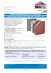
APPROVAL INSPECTION TESTING CERTIFICATION Knauf Insulation Ltd P O Box 10 Stafford Road St Helens Merseyside WA10 3NS Tel: 01744 766600 Fax: 01744 766750 TECHNICAL APPROVALS FOR CONSTRUCTION Agrément Certificate 12/4953 e-mail: [email protected] website: www.knaufinsulation.com Product Sheet 1 KNAUF EXTERNAL WALL INSULATION SYSTEMS KNAUF THERMOSHELL ROCK PLUS EXTERNAL WALL INSULATION SYSTEMS This Agrément Certificate Product Sheet (1) relates to the Knauf ThermoShell Rock Plus External Wall Insulation Systems, comprising of a mechanically fixed mineral wool insulation slabs (with supplementary adhesive), mesh-reinforced render coat and render finish, and suitable for use on new or existing domestic and non-domestic buildings. (1) Hereinafter referred to as ‘Certificate’. CERTIFICATION INCLUDES: • factors relating to compliance with Building Regulations where applicable • factors relating to additional non-regulatory information where applicable • independently verified technical specification • assessment criteria and technical investigations • design considerations • installation guidance • regular surveillance of production • formal three-yearly review. KEY FACTORS ASSESSED Thermal performance — the system can be used to improve the thermal performance of external walls and contribute to meet the Building Regulations (see section 6). Strength and stability — to the system can adequately resist wind loads and, in certain applications, impact damage (see section 7). Behaviour in relation to fire — the system has achieved classification Class A2 – s2, d0 for surface spread of flame in accordance with BS EN 13501-1 : 2007 (see section 8). Risk of condensation — the system can contribute to limiting the risk of interstitial and surface condensation (see section 11). Durability — with appropriate care and maintenance, the system should remain effective for at least 30 years provided the guidance as stated in section 13 are fully implemented. The BBA has awarded this Certificate to the company named above for the system described herein. This system has been assessed by the BBA as being fit for its intended use provided it is installed, used and maintained as set out in this Certificate. On behalf of the British Board of Agrément Date of First issue: 19 March 2013 Sean Moriarty — Head of Approvals Greg Cooper Energy and Ventilation Chief Executive The BBA is a UKAS accredited certification body — Number 113. The schedule of the current scope of accreditation for product certification is available in pdf format via the UKAS link on the BBA website at www.bbacerts.co.uk Readers are advised to check the validity and latest issue number of this Agrément Certificate by either referring to the BBA website or contacting the BBA direct. British Board of Agrément Bucknalls Lane Watford Herts WD25 9BA ©2013 Page 1 of 16 tel: 01923 665300 fax: 01923 665301 e-mail: [email protected] website: www.bbacerts.co.uk Regulations In the opinion of the BBA, the Knauf ThermoShell Rock Plus External Wall Insulation Systems, if installed, used and maintained in accordance with this Certificate, will meet or contribute to meeting the relevant requirements of the following Building Regulations (the presence of a UK map indicates that the subject is related to the Building Regulations in the region or regions of the UK depicted): The Building Regulations 2010 (England and Wales) (as amended) Requirement: A1 Loading Comment: Requirement: B4(1) External fire spread The system can sustain and transmit wind loads to the substrate wall. See section 7.4 of this Certificate. Comment: The system is classified Class A2 – s2, d0 and, therefore, can meet this Requirement. See sections 8.1, 8.3, 8.6 and 8.7 of this Certificate. Requirement: C2(b) Resistance to moisture Comment: The system provides a degree of protection against rain ingress. See sections 4.4, 10.1 and 10.3 of this Certificate. Requirement: C2(c) Resistance to moisture Comment: The walls contribute to minimising the risk of interstitial and surface condensation. See sections 4.6, 11.1, 11.2, 11.4 and 11.6 of this Certificate. Requirement: L1(a)(i) Conservation of fuel and power Comment: Regulation: 7 Materials and workmanship Comment: Regulation: 26 CO2 emission rate for new buildings The system can contribute to meeting this Requirement. See sections 6.2 and 6.3 of this Certificate. The system is acceptable. See section 13.1 and the Installation part of this Certificate. The system can contribute to meeting this Regulation. See sections 6.2 and 6.3 of this Certificate. Comment: The Building (Scotland) Regulations 2004 (as amended) Regulation: 8(1)(2) Fitness and durability of materials and workmanship The system can contribute to a construction meeting this Regulation. See sections 12.1 and 13.1 and the Installation part of this Certificate. Comment: Regulation: Standard: 9 1.1 Building standards applicable to construction Structure Comment: Standard: 2.6 Spread to neighbouring buildings The system can sustain and transmit wind loads to the substrate wall. See section 7.4 of this Certificate. The external surface of the system is classified A2 – s2, d0 surface spread of flame classification, with reference to clauses 2.6.1(1)(2), 2.6.2(1)(2), 2.6.4(1)(2), 2.6.5(1) and 2.6.6(2). See sections 8.1, 8.3 and 8.8 of this Certificate. Comment: Standard: 2.7 Standard: 3.10 3.15 6.1(b) 6.2 Carbon dioxide emissions Building insulation envelope The system can contribute to satisfying these Standards, with reference to clauses (or part of) 6.1.1(1), 6.1.2(1)(2), 6.1.3(1)(2), 6.1.4(2), 6.1.6(1), 6.1.8(2), 6.1.10(2), 6.2.1(1)(2), 6.2.3(1), 6.2.4(1), 6.2.5(1)(2), 6.2.6(2), 6.2.7(2), 6.2.11(1) and 6.2.13(2). See sections 6.2 and 6.3 of this Certificate. Comment: Standard: Condensation Walls insulated with the system can satisfy this Standard, with reference to clauses 3.15.1(1)(2), 3.15.4(1)(2) and 3.15.5(1)(2). See sections 4.6 and 11.5 and 11.6 of this Certificate. Comment: Standard: Standard: Precipitation Walls insulated with the system will contribute to a construction satisfying this Standard, with reference to clauses 3.10.1(1)(2) and 3.10.6(1)(2). See sections 4.4, 10.1 and 10.3 of this Certificate. Comment: Standard: Spread on external walls The system incorporates materials which would not be classed as ‘non-combustible’ as defined in this Standard, with reference to clauses 2.7.1(1)(2) and 2.7.2(2) and Annex 2A(1). See sections 8.1, 8.3 and 8.8 of this Certificate. Comment: 7.1(a)(b) Statement of sustainability The system can contribute to meeting the relevant requirements of Regulation 9, Standards 1 to 6, and, therefore, will contribute to a construction meeting a bronze level of sustainability as defined in this Standard. Comment: (1) Technical Handbook (Domestic). (2) Technical Handbook (Non-Domestic). The Building Regulations (Northern Ireland) 2012 Regulation: 23 Fitness of materials and workmanship Comment: Regulation: 28 Resistance to moisture and weather Comment: The system is acceptable. See sections 13.1 the Installation part of this Certificate. Walls insulated with the system will satisfy this Regulation. See sections 4.4, 10.1 and 10.3 of this Certificate. Page 2 of 16 Regulation: 29 Condensation Walls insulated with the system can satisfy this Regulation. See sections 4.6, 11.4 and 11.6 of this Certificate. Comment: Regulation: 30 Stability Comment: Regulation: 36(a) External fire spread The system can sustain and transmit wind loads to the substrate wall. See section 7.4 of this Certificate. The external surface of the system is classified A2 – s2, d0 surface spread of flame classification and can satisfy this Regulation. See sections 8.1, 8.3, 8.6 and 8.7 of this Certificate. Comment: Regulation: Regulation: 39(a)(i) 40 Comment: Conservation measures Target carbon dioxide emission rate The system can contribute to satisfying these Regulations. See sections 6.2 and 6.3 of this Certificate. Construction (Design and Management) Regulations 2007 Construction (Design and Management) Regulations (Northern Ireland) 2007 Information in this Certificate may assist the client, CDM co-ordinator, designer and contractors to address their obligations under these Regulations. See section: 3 Delivery and site handling (3.1) of this Certificate. Additional Information NHBC Standards 2013 NHBC accepts the use of the Knauf ThermoShell Rock Plus External Wall Insulation Systems for masonry walls, when installed and used in accordance with this Certificate, in relation to NHBC Standards, Part 6 Superstructure (excluding roofs), Chapter 6.9 Curtain Walling and cladding. Technical Specification 1 Description 1.1 The Knauf ThermoShell Rock Plus External Wall Insulation Systems are for use on external walls of masonry construction. The insulation systems are mechanically fixed to the substrate wall with a minimum of four fixings per m2 in conjunction with a supplementary adhesive (minimum coverage 40% and with minimum thickness 10mm). 1.2 The components of the basic wall system (see Figure 1), from the external substrate wall, comprises of the following: • Knauf TS-Bond — adhesive, grey bonding reinforcing lime-cement mortar with micro-fibres, fine additives and bonding agent, applied to a thickness of 10 mm • Knauf ThermoShell Rock Plus (Rocksilk EWI Slab Plus mineral wool insulation) — 1200 mm by 600 mm in thicknesses of between 50 mm and 150 mm in 10 mm increments, density 140 kg·m–3, tensile resistance 10 kPa • Knauf TS-Fixings — mechanical anchor of adequate length to suit the substrate and insulation thickness, approved and supplied by the Certificate holder, and selected from: Ejotherm STR U and NT U • Knauf TS-Bond — basecoat, grey bonding reinforcing lime-cement mortar with micro-fibres, fine additives and bonding agent applied in a 6 mm to 7 mm thickness. Please note: basecoat and adhesive are prepared using Knauf TS-Bond powder mixed with water • Knauf TS-Reinforcing Mesh — woven glassfibre mesh (mesh size 4 mm by 4 mm) with a residual strength after ageing of at least 20 N·mm–1 and a mass of 165 g·m–2, mesh is embedded into the basecoat render • Knauf TS-Primer M — bonding primer with a quartz admixture for use with all basecoat renders to provide superior adhesion for the TS-Mineral finish, applied at a nominal 1 mm thickness • Knauf TS-Primer S — bonding primer containing polymer binders for use with thin-coat rubbed or floated renders to provide superior adhesion for the TS-Silicon finish, applied at a nominal 1 mm thickness • Knauf TS-Mineral — a dry powder mix cement based mineral finish top coat render available in 1.5 mm, 2 mm, 3 mm and 5 mm grain sizes applied in thicknesses of 1.5 mm, 2 mm, 3 mm and 5 mm • Knauf TS-Silicone — a water based silicone resin topcoat render available in 1.5 mm, 2 mm and 2.5 mm grain size applied in thicknesses of 1.5 mm, 2 mm and 2.5 mm • Knauf TS-Dash — a dry powder pre-mixed cement based dashing aggregate receiving render for use with Knauf TS-Spar aggregate which is applied to a thickness of 6 mm to 10 mm • Knauf TS-Equalizer — a silicone resin façade paint designed for the over-coating of mineral renders. The paint is applied at a nominal 1 mm thickness • Knauf TS-Self Clean — a premium silicone resin façade paint with self-cleaning technology to reduce the adherence of dirt particles designed for the over-coating of mineral renders. The paint is applied at a nominal 1 mm thickness • Knauf TS-Spar — a natural range of washed dry dashing aggregate available in a range of standard colours and aggregate sizes. TS-Spar is suitable for use with the TS-Dash dashing receiver. Page 3 of 16 Figure 1 Knauf ThermoShell Rock Plus External Wall Insulation System finish render reinforcing mesh embedded in render insulation slab substrate adhesive existing render on substrate mechanical fixing Ancillary materials/components 1.3 Ancillary materials used with the system must be approved by the Certificate holder. Those materials either supplied by the Certificate holder or bought items for use in particular locations/forms of construction include: • starter-tracks (to suit each insulation thickness) • silicone sealant • end stops • sills • render beads • stainless steel fire-fixings. 1.4 Ancillary items outside the scope of this Certificate and approved by the Certificate holder, but which may be required to ensure that the completed construction complies with the building regulations and is fit for purpose, include: • algicide • expansion profile • sealing tape. 2 Manufacture 2.1 To ensure product quality is consistently maintained to the required specification, the BBA has: • • • • • • agreed with the Certificate holder/manufacturer the quality control procedures and product testing to be undertaken assessed and agreed the quality control operated over batches of incoming materials monitored the production process and verified that it is in accordance with the documented process evaluated the process for management of non-conformities checked that equipment has been properly tested and calibrated undertaken to carry out the above measures on a regular basis through a surveillance process to ensure that standards are maintained and that the product or system remains as Certificated. 2.3 The management system of Knauf Insulation Ltd has been assessed and registered as meeting the requirements of BS EN ISO 9001 : 2008 by Bureau Veritas (Certificate BE001519-1). 3 Delivery and site handling 3.1 Components are delivered in the packaging and quantities listed in Table 1. Each basecoat bag carries the product identification and manufacturer’s batch number. Damaged, contaminated or wet materials should not be used. 3.2 The insulation must be protected from prolonged exposure to sunlight, either by storing opened packs under cover or re-covering with opaque sheeting. In addition, the insulation should be stored on a firm, clean, level base, off the ground and under cover until required for use. Care must be taken when handling the insulation boards to avoid both damage and contact with solvents or bitumen products. The boards must not be exposed to open flame or other ignition sources. Page 4 of 16 Table 1 Component supply details Component Quantity and packaging Knauf TS-Bond (used for adhesive and the basecoat) 25 kg bag Kanuf ThermoShell Rock Plus (Rocksilk EWI Slab Plus mineral wool insulation) per pallet Knauf TS-Reinforcing Mesh (glassfibre reinforcing mesh) 50 m2 roll Knauf TS-Primer M and TS-Primer S (primers) 15 kg tub Knauf ThermoShell TS-Mineral and TS-Silicone (finishing coats) Knauf TS-Dash (dash receiving coat) 25 kg bag or 25 kg tub 25 kg bag Knauf TS-Equalizer or TS-Self Clean (decorative coats) Knauf TS-Spar (aggregate decorative coat) 12.5 litre tub 25 kg bag Knauf TS-Fixings (mechanical fixings) 100 per box 3.3 The adhesive, basecoat and finishes must be stored in dry conditions, off the ground, and protected from moisture and frost. Assessment and Technical Investigations The following is a summary of the assessment and technical investigations carried out on the Knauf ThermoShell Rock Plus External Wall Insulation Systems using Rocksilk EWI Slab Plus. Design Considerations 4 General 4.1 The Knauf ThermoShell Rock Plus External Wall Insulation Systems, when installed in accordance with this Certificate, are effective in reducing the thermal transmittance (U value) of external walls in new and existing buildings. It is essential that the detailing techniques specified in this Certificate are carried out to a high standard if the ingress of water into the insulation is to be avoided and the full thermal benefit obtained from the systems. Only details approved by the Certificate holder must be used. 4.2 The system will improve the weather resistance of a wall and provides a decorative finish. However, these systems may only be installed where other potential sources of moisture penetration have been dealt with separately and where there are no signs of dampness on the inner surface of the wall, other than those caused solely by condensation. The system can be used to overcome condensation occurring on an internal wall surface. 4.3 Existing buildings, subject to national Building Regulations, should have exterior wall surfaces in accordance with section 15 Site survey and preliminary work in the Installation part of this Certificate. 4.4 New buildings subject to national Building Regulations should be constructed in accordance with the relevant recommendations of: • BS EN 1996-1-1 : 2005, BS EN 1996-1-2 : 2005, BS EN 1996-2 : 2006 and BS EN 1996-3 : 2006 • BS 8000-3 : 2001. 4.5 Other new buildings, not subject to any regulatory requirements should also be built in accordance with BS EN 1996-2 : 2006. 4.6 When using the system, the recommendations of BS 5250 : 2011 should be followed and consideration given to the overall design to minimise the risk of condensation. 4.7 The effect of the installation of the systems on the acoustic performance of a construction is outside the scope of this Certificate. 5 Practicability of installation The system should be installed only by specialised contractors who have successfully undergone training and registration by the Certificate holder. Note: The BBA operates a UKAS Accredited Approved Installer Scheme for external wall insulation; details of installer companies approved are included on the BBA’s website (www.bbacerts.co.uk). 6 Thermal performance 6.1 Calculations of the thermal transmittance (U value) should be carried out in accordance with BS EN ISO 6946 : 2007 and BRE Report (BR 443 : 2006) Conventions for U-value calculations, using the insulation manufacturer’s declared thermal conductivity (90/90 value) of 0.038 W·m–1·K–1 for Rocksilk EWI Slab Plus insulation product. Page 5 of 16 6.2 The U value of an installation will depend on the selected insulation thickness, the fixing method, the insulating value of the substrate masonry and its internal finish. Calculated U values for example constructions are given in Table 2 and are based on four fixings per m2 with the manufacturer’s declared thermal conductivity. Table 2 Insulation thickness required to achieve design U values given in national Building Regulations ThermoShell Rock Plus U value(1) (W·m–2·K–1) Thickness of insulation(2) (mm) 0.19 — 0.26 140 0.28 130 0.30 120 (1) Values derived using 200 mm thick dense concrete block with thermal conductivity of 1.75 W·m–1·K–1, with 12 mm thick layer of dense plaster finish. Including four fixings (STR U/ NT U) with a point of thermal transmittance of 0.002 W·m–1·K–1 (assumes fixing penetrates the whole insulation layer). (2) Based upon incremental insulation thickness of 10 mm. 6.3 The system can maintain, or contribute to maintaining, continuity of thermal insulation around openings and at junctions between external walls and other building elements. Details shown in Figures 8 and 9 will allow use of the default psi values for Accredited Construction details in Emission Rate calculations to SAP 2009 or the Simplified Building Energy Model (SBEM). Guidance on limiting heat loss at junctions can be found in: England and Wales — Approved Documents to Part L and, for new thermal elements to existing buildings, Accredited Construction Details (version 1.0). For new-build, see also SAP 2009, Appendix K, and the iSBEM User Manual. Scotland — Accredited Construction Details (Scotland) Northern Ireland — Accredited Construction Details (version 1.0). 6.4 Care must be taken to ensure an appropriate thickness of insulation is used, particularly at points such as junctions between floors and walls and at window and door reveals, to avoid thermal bridging and reduce the risk of condensation forming at these points. Items such as windows and doors should be selected taking into account the thickness of insulation required at the reveals to help prevent water ingress. 7 Strength and stability 7.1 When installed on masonry or concrete walls, the system can adequately transfer to the wall the self-weight and negative and positive (suction and pressure) wind loads normally experienced in the United Kingdom. 7.2 Positive wind load (pressure) is transferred to the substrate wall directly via bearing and compression of the decorative/finish coat, insulation and adhesive. 7.3 Negative wind pressure (suction) is resisted by the bond between each component. The insulation boards are retained by the external wall insulation system anchors and adhesive. 7.4 The wind loads on the wall should be calculated in accordance with BS EN 1991-1-4 : 2005. Special consideration should be given to locations with high wind-load pressure coefficients as additional fixings may be necessary. In accordance with BS EN 1990 : 2002, it is recommended that a load factor of 1.5 is used to determine the ultimate wind load to be resisted by the system. 7.5 Assessment of structural performance for individual installations should be carried out by a suitably qualified engineer or other appropriately qualified person to confirm that: • the substrate wall has adequate strength to resist additional loads that may be applied as a result of installing the system, ignoring any positive contribution that may occur from the insulation system • the proposed systems and associated fixing pattern provides adequate resistance to negative wind loads [based on the results of the site investigation and test results given in Table 3 (see section 7.6)] • an appropriate number of site-specific pull-out tests must be conducted on the substrate of the building to determine the minimum resistance to failure of the fixings. The characteristic pull-out resistance should be determined in accordance with the guidance given in ETAG 014 : 2002, Annex D (ie by calculating the mean of the lowest five values and multiplying by 0.6). In accordance with this guideline, a safety factor of two is applied to this figure to establish the design value to resist ultimate loads. 7.6 The number of fixings and the span between fixings should be determined by the system designer. Provided the substrate wall is suitable and an appropriate fixing is used, the mechanical fixings will transfer the weight of the render insulation system to the substrate wall. The fixing must be selected to give adequate support to the weight of the system at the minimum spacing given in this Certificate. 7.7 Typical characteristic pull-out strengths for the fixings are given in Table 3, however these values are dependent on the substrate and the fixing must be selected to suit the load and the substrate concerned. A minimum of one metal fixing per square metre is required to satisfy fire regulations (see section 8). Page 6 of 16 7.8 The resistance forces data given in Table 4 are the results of calculations based upon: • fixings arranged in the pattern described and shown in section 16.6 and Figure 5 respectively • characteristic pull-through resistance value per anchor determined by the tests conducted on anchors with 60 mm diameter plates. The design pull-through resistance value per anchor is then derived by using this characteristic value from tests results with a factor of safety of 2.5 applied. Table 3 Fixings — typical characteristic pull-out strengths Fixing type Substrate ETA Number Drill diameter (mm) Embedment depth (mm) Typical pull-out strength(1) (kN) Ejotherm: NT U Concrete/solid brick ETA-05/0009 8 35 1.2 (concrete) 1.5 (brick) Ejotherm: STR U Concrete/solid brick ETA-04/0023 8 50 1.5 (concrete) 1.5 (brick) (1) Values are determined in accordance with ETAG 014 : 2002 and dependent on the substrate. Table 4 Example calculation to establish the ultimate wind load capacity Factor Value Insulation thickness(1) (mm) 100 Plate diameter of anchor (mm) 60 Characteristic pull-through resistance(2) (per anchor fixed at the board joint) (N) Factor of safety(3) 2.5 Design pull-through resistance per anchor (N) (4) Characteristic pull-out resistance(5) per anchor (N) Factor of safety 333.7 133.48 1200 2 (6) Design pull-out resistance per anchor (N) 600 Limiting design value(7) per anchor (N) 133.48 Limiting design value per board(8) (with 4 fixings per m2) (N) 533.92 Area of board (m2) 0.72 Limiting pressure (N·m ) 741.56 –2 (1) Calculation based on insulation board 1200 mm by 600 mm (total area 0.72 m2) attached by four fixings per m2. (2) Characteristic pull-through resistance value per anchor is calculated as described in section 7.8. (3) The safety factor of 2.5 is based on the assumption that all insulation boards are quality control tested to establish the tensile strength perpendicular to the face of the board. (4) From site-specific pull-out test (using characteristic pull-through resistance with factor of safety of 2.5 applied). (5) Refer to section 7.7 and Table 3. (6) In accordance with the guidance given in ETAG 014 : 2002, a safety factor of two is applied to establish the design value to resist ultimate loads. (7) The lesser of the board design pull-through resistance and the anchor design pull-out resistance. (8) Board design pull-through resistance multiplied by the number of fixings, based upon the limiting resistance. Impact resistance 7.9 The insulation system with the reinforcing mesh have adequate resistance to impact damage when used in a zone liable to impacts from thrown or kicked objects. Hard body impact test were carried out in accordance with ETAG 004 : 2011, Section 6.1.3.3, Table 8. The system is suitable for use in category I(1) and category II(2). (1) Use category I – a zone readily accessible at ground level to the public and vulnerable to hard body impacts but not subjected to abnormally rough use. (2) Use category II – a zone liable to impacts from thrown or kicked objects, but in public locations where the height of the system will limit the size of the impact; or at lower levels where access to the building is primarily to those with some incentive to exercise care. 8 Behaviour in relation to fire 8.1 The surface spread of flame classification for the system in accordance with BS EN 13501-1 : 2007, is Class A2 – s2, d0. 8.2 These ratings apply to the full range of colours covered by the Certificate, with the organic content less than 0.4%. 8.3 The insulation material in isolation is non-combustible and classified as class A1 in accordance with BS EN 13501-1 : 2007. Page 7 of 16 8.4 In multi-storey applications, a minimum of one stainless anchor per square metre is required above the first floor. The anchor is applied to prevent collapse should the insulation be lost to fire and must be designed to resist the bending and shear stresses resulting from the dead load from the render. 8.5 Requirements under the various national Building Regulations are: England and Wales and Northern Ireland 8.6 The external surfaces of the system are to Class A2 – s2, d0 in accordance with BS EN 13501-1 : 2007 and, therefore, are considered suitable for use on or at any distance from the boundary. 8.7 The system incorporating mineral wool insulation may be used without height restriction. Scotland Technical Handbooks (Domestic and Non-Domestic) Standard 2.6 Spread to neighbouring buildings 8.8 The system is classified as A2 in accordance with BS EN 13501-2 : 2007 (non-combustible in Annex 2.B(1) and Annex 2.E(2)) and, therefore, may be disregarded for the purposes of calculating unprotected areas for the wall behind the cladding and can be used within 1 m of the boundary. (1) Technical Handbook (Domestic). (2) Technical Handbook (Non-Domestic). 9 Proximity of flues and appliances When the system is installed in close proximity to certain flue pipes the relevant provisions of the national Building Regulations must be met: England and Wales — Approved Document J Scotland — Mandatory Standard 3.19, clause 3.19.4(1)(2) (1) Technical Handbook (Domestic). (2) Technical Handbook (Non-Domestic). Northern Ireland — Technical Booklet L. 10 Rain penetration 10.1 The system will provide a degree of protection against rain ingress. However, care should be taken to ensure that walls are adequately weather tight prior to the application of the insulation system. The insulation system may only be installed where there are no signs of dampness on the inner surface of the substrate other than those caused solely by condensation. 10.2 Designers and installers should take particular care over detailing around openings, penetrations and movement joints, to minimise the risk of rain ingress; only details approved by the Certificate holder should be used. 10.3 For externally insulated single-leaf masonry walls, guidance is given in BS EN 1996-1-1 : 2005, BS EN 998-1 : 2010 and BS EN 998-2 : 2010 on minimum thickness of masonry walls required for the different exposure categories. 10.4 Guidance given in BRE Report (BR 262 : 2002) Thermal insulation: avoiding risks should be followed in connection with the weathertightness of solid wall constructions. The designer should select a construction appropriate to the local wind-driven rain index, paying due regard to the design detailing, workmanship and materials to be used. Additional guidance can be found in: England and Wales — Approved Document C, Section 5 Scotland — Mandatory Standard 3.10(1)(2) (1) Technical Handbook (Domestic). (2) Technical Handbook (Non-Domestic). Northern Ireland — Technical Booklet C, Section 2. 10.5 When using the system, consideration must be given to the overall design to minimise the risk of condensation, and the recommendations of BS 5250 : 2011 should be followed. 10.6 At the tops of walls, the system should be protected by an adequate overhang or other detail designed for use with this type of system (see sections 16.19). 10.7 The fixing of rainwater goods, satellite dishes, clothes lines, hanging baskets and similar items is outside the scope of this Certificate. 10.8 It is essential that the system is installed and maintained in accordance with the conditions set out in this Certificate. Page 8 of 16 11 Risk of condensation 11.1 When using the system, consideration must be given to the overall design to minimise the risk of condensation, and the recommendations of the BS 5250 : 2011 should be followed. 11.2 Designers should ensure that an appropriate condensation risk analysis has been carried out for all parts of a construction, including openings and penetrations at junctions between the insulation system and windows to ensure that condensation does not occur at the surface or within. 11.3 The mineral wool insulation slabs have a water vapour diffusion resistance factor (µ value) of 1, as taken from BS EN ISO 10456 : 2007, Table 4. Surface condensation 11.4 Walls will adequately limit the risk of surface condensation when the thermal transmittance (U value) does not exceed 0.7 W·m–2·K–1 at any point and the junctions with other elements and openings comply with section 6.3. 11.5 Walls will adequately limit the risk of surface condensation when the thermal transmittance (U value) does not exceed 1.2 W·m–2·K–1 at any point. Guidance may be obtained from BS 5250 : 2011, Section 4, and BRE Report (BR 262 : 2002). Interstitial condensation 11.6 Walls incorporating the system will adequately limit the risk of interstitial condensation when they are designed and constructed in accordance with BS 5250 : 2011, Section 4 and Annex D. 11.7 The system has a water vapour resistance such that, under the types of conditions likely to occur in a dwelling in the United Kingdom, interstitial condensation should not occur in the insulation. 11.8 If the system is to be used on the external walls of rooms expected to have continuous high humidity, care must be taken in the design of the rooms to avoid possible problems from the formation of interstitial condensation. 12 Maintenance and repair • • • • • • 12.1 For each installation, a detailed maintenance plan must be prepared and provided to the building manager/owner on completion. As a minimum, this should include an inspection for evidence of defects 12 months after the application and subsequently every five years. Planned inspection and maintenance should include: visual inspection of the render for signs of damage. Cracks in the render must not exceed 0.2 mm examination of the sealant around openings and service entry points visual inspection of architectural details designed to shed water to confirm that they are performing properly visual inspection to ensure that water is not leaking from external downpipes or gutters; such leakage could penetrate the rendering necessary repairs should be effected immediately and the sealant joints at window and door frames replaced at regular intervals maintenance schedules should include the replacement and resealing of joints, for example between the insulation systems and window and door frame. 12.2 Damaged areas must be repaired using the appropriate components and procedures detailed in the Certificate holder’s installation instructions and taking into account the relevant recommendations of BS EN 13914-1 : 2005. 13 Durability 13.1 The results of accelerated ageing tests in accordance with ETAG 004 : 2011 indicate that the system is durable. The system should remain effective for at least 30 years, provided any damage to the surface finish is repaired immediately, and regular maintenance is undertaken (see section 12). This includes checks on joints in the system and on penetrations to enable corrective action to be taken to rectify the defects. 13.2 The finish may become discoloured with time. The rate at which this occurs will depend on the initial colour, the degree of exposure, the level of atmospheric pollution and the design and detailing of the wall. In common with traditional renders, discoloration by algae and lichens may occur in wet areas. Installation 14 Site survey and preliminary work 14.1 A pre-installation survey of the property is carried out to determine suitability for treatment and the need for any necessary repairs to the building structure before application of the system. A specification is prepared for each elevation of the building indicating: • position of starter tracks and render beads Page 9 of 16 • • • • • • • position and amount of reinforcing mesh and corner mesh detailing around windows, doors and at eaves any alterations to external plumbing damp-proof course (dpc) level location and type of weather seals to be used areas where suitable sealants must be used position of fire barriers. 14.2 Trial tests are conducted on the wall to determine the pull-out resistance of the proposed mechanical fixings. An assessment and recommendation is made on the type and number of fixings required to withstand the building’s expected wind loading based on calculation using the test data, the relevant wind speed data for the site and together with the Certificate holder’s recommendations. It is recommended that the minimum layout of fixings (see section 16.6 and Figure 5) as specified by the Certificate holder, should be followed. 14.3 Surfaces should be sound, clean, and free from loose material. The flatness of surfaces must be checked; this may be achieved by using a straight-edge spanning the storey height. Excessive irregularities, ie greater than 10 mm, must be made good prior to installation to ensure that the insulation boards or slabs are installed with a smooth, in-plane finished surface. 14.4 On existing buildings, purpose-made window sills must be fitted to extend beyond the finished face of the system. New buildings should incorporate suitably deep sills. 14.5 Internal wet work, eg screeding or plastering, should be completed and allowed to dry prior to the application of a system. 14.6 Where surfaces are covered with an existing rendering it is essential that the bond between the background and the render is adequate. All loose areas must be hacked off and reinstated. 14.7 Where mechanical fixings are to be used to secure the system, trial tests should be conducted on the wall by the Certificate holder or their approved applicators (see section 16) to determine the pull-over resistance of the proposed mechanical fixings. 14.8 All modifications, such as provision for cavity barriers and fire stopping (see section 8) and necessary repairs to the building must be completed before installation commences. 14.9 It is recommended that external plumbing be removed before installation, and any necessary alterations made to underground drainage to accommodate repositioning of the plumbing on the finished face of the system. 15 Approved installers Application of the system, within the context of this Certificate, is carried out by approved installers recommended or recognised by the Certificate holder. Such an installer is a company: • employing operatives who have been trained and approved by the Certificate holder to install the system • which has undertaken to comply with the Certificate holder’s application procedure, containing the requirement for each application team to include at least one member operative trained by the Certificate holder • subject to at least one inspection per annum by the Certificate holder to ensure suitable site practices are being employed. This may include unannounced site inspections. 16 Procedure General 16.1 Installation of the system should be carried out in accordance with the Certificate holder’s current installation instructions. 16.2 Weather conditions should be monitored to ensure correct application and curing conditions. The insulation board adhesive, basecoat and rendering must not be applied when either, exposure to frost is likely, in damp/wet conditions or at temperatures below 5°C or above 30°C, or where these temperatures are likely to be exceeded during the curing period. The render must be protected from rapid drying and should not be applied on elevations in direct sunlight or where the substrate is hot. 16.3 All rendering should be in accordance with the relevant recommendations of BS EN 13914-1 : 2005 and BS EN 13914-2 : 2005. Positioning and securing insulation boards 16.4 A metal base-profile should be fixed at a position at or above dpc level to coincide with the lower edge of the insulation (see Figure 2). Page 10 of 16 Figure 2 Base detail insulation slab reinforcing mesh embedded in render finish render adhesive substrate mechanical fixing starter-track fixed to substrate dpc 16.5 Insulation boards should be installed with staggered joints, including staggered joints at the building corners, from the base-profile upward (see Figure 3). The insulation boards should be bonded to the wall using adhesive (Knauf TS-Bond) as described in section 1.2. Knauf TS-Bond is mixed in a suitable container using clean water and an electrical paddle mixer. The adhesive is applied around the board perimeter and with additional dabs in the middle of board as illustrated in Figure 4. The application of adhesive should cover at least 40 per cent of the board. The adhesive mix must be used within two hours of mixing. 16.6 Mechanical fixings are installed into holes drilled into the substrate wall at insulation board joints (see Figure 5). The fixings must fit tightly but care must be taken to ensure that they are not overdriven. Figure 3 Board layout on the wall and at the corners of a building Page 11 of 16 Figure 4 Adhesive pattern on slab Figure 5 Mechanical fixing pattern 16.7 Care must be taken to ensure that all insulation board edges are butted tightly together, and alignment is checked as work proceeds. The surface of the boards should be smooth without large protrusion or irregularities. Any gaps between the boards should be filled with strips of the insulation material. 16.8 To fit around details such as doors and windows, insulation boards may be cut with a sharp knife or a fine-tooth saw. Movement joints 16.9 Movement joints should be incorporated where required. Existing structural expansion joints should be extended through to the surface of the insulation system (see Figure 6). Figure 6 Movement joint adhesive substrate movement joint insulation slab reinforcing mesh embedded in render finish render 16.10 At all locations where there is a risk of insulant exposure, eg window reveals or eaves, the system must be protected by such features as an adequate overhang or by purpose-made sub-sills, seals or flashing. Building corners, door and window heads and jambs are formed using angle beads in accordance with the Certificate holder’s instructions. 16.11 Prior to applying the finish and/or decorative coat(s), the relevant seals are positioned and installed at all openings (eg windows and doors), overhanging eaves, gas and electric meter boxes, wall vents or where the render abuts any other building material or surface. This helps to reduce the risk of water ingress into the structure. Page 12 of 16 Reinforcing 16.12 The Knauf TS-Bond (can be used as basecoat as well as insulation board adhesive) should be mixed with water to a homogeneous paste using an electrical paddle mixer. Once mixed, the basecoat must be used within two hours. The basecoat is trowel-applied to the insulation to a thickness of 6 mm to 7 mm. Figure 7 Reinforcing at opening edges 16.13 Sections of the reinforcing mesh (Knauf TS-Reinforcing Mesh) should be placed at areas such as the corners of windows, doorways, and other similar openings prior to the installation of entire wall with reinforcing mesh (see Figure 7). The mesh is positioned into the basecoat immediately after its application and trowelled into position ensuring it is fully embedded within the basecoat. The top surface of the basecoat should be trowelled smooth. 16.14 Where required stainless steel fire-fixings must be provided at the rate of one per square metre, the fixing design should take account of the extra duty required under fire conditions. These fixings are inserted into the centre of each board before the basecoat is fully cured. 16.15 The basecoat (Knauf TS-Bond) must be allowed to cure for at least one day per mm applied prior to the application of the primer coat (Knauf TS-Primer M or TS-Primer S). 16.16 Mineral and Silicone systems – primers are applied as required in accordance with the Certificate holder’s instructions and allowed to fully dry prior to the application of the finishing coat (Knauf TS-Mineral or TS-Silicone). For dash systems the dash receiver is applied in accordance with the certificate holder’s instructions prior to the application of the aggregate finishing coat (Knauf TS-Spar). Rendering and finishing 16.17 Mineral silicone and Self clean finishes – the finish coat can be trowel-applied or spray applied in accordance with the Certificate holder’s instructions, after the primer has dried. Knauf Decorative Coat (either TS-Equalizer or TS-Self Clean) is applied over the finishing coat depending on which system is implemented. For dash systems the aggregate finishing coat (Knauf TS-Spar) is applied into the wet dash receiver. 16.18 To prevent the finish from drying too rapidly, it should not be applied in direct sunlight. Continuous surfaces must be completed without a break. 16.19 At the tops of walls, the system should be protected by an adequate overhang or other detail designed for use with this type of system. Care should be taken in the detailing of the system around features such as openings, projections and at eaves (see Figure 8) to ensure adequate protection against water ingress and to limit the risk of water penetrating the system. Page 13 of 16 Figure 8 Typical details – Eaves and opening head finish render reinforcing mesh embedded in render insulation slab adhesive lintel bead and joint sealing tape reinforcing mesh embedded in render substrate adhesive finish render insulation slab eaves opening head 16.20 Care must be taken in the detailing of the system around openings and projections (see Figure 9). 16.21 On completion of the installation, external fittings, eg rainwater goods, are re-fixed through the system into the substrate. Repair 16.22 Damaged areas must be repaired using the appropriate components and procedures detailed in the Certificate holder’s installation instructions and taking into account the relevant recommendations of BS EN 13914-1 : 2005. Figure 9 Oversill detail window sill sill band joint sealing tape finish render reinforcing mesh embedded in render insulation slab adhesive substrate Page 14 of 16 Technical Investigations 17 Investigations An examination was made of test data relating to: • • • • • • • • • • surface spread of flame tests density of insulation slab Bond-strength hygrothermal performance resistance to freeze/thaw resistance to impact water absorption of render water vapour permeability durability of finish thermal conductivity Bibliography BS 5250 : 2011 Code of practice for control of condensation in buildings BS 8000-3 : 2001 Workmanship on building sites — Code of practice for masonry BS EN 998-1 : 2010 Specification for mortar for masonry — Rendering and plastering mortar BS EN 998-2 : 2010 Specification for mortar for masonry — Masonry mortar BS EN 1990 : 2002 Eurocode — Basis of structural design BS EN 1991-1-4 : 2005 Eurocode 1 : Actions on structures — General actions — Wind actions BS EN 1996-1-1 : 2005 Eurocode 6 : Design of masonry structures — General rules for reinforced and unreinforced masonry structures BS EN 1996-1-2 : 2005 Eurocode 6 : Design of masonry structures — General rules — Structural fire design BS EN 1996-2 : 2006 Eurocode 6 : Design of masonry structures — Design considerations, selection of materials and execution of masonry BS EN 1996-3 : 2006 Eurocode 6 : Design of masonry structures : Simplified calculation methods for unreinforced masonry structures BS EN 13501-1 : 2007 Fire classification of construction products and building elements — Classification using test data from reaction to fire tests BS EN 13501-2 : 2007 Fire classification of construction products and building elements — Classification using data from fire resistance tests, excluding ventilation services BS EN 13914-1 : 2005 Design, preparation and application of external rendering and internal plastering — External rendering BS EN 13914-2 : 2005 Design, preparation and application of external rendering and internal plastering — Design considerations and essential principles for internal plastering BS EN ISO 6946 : 2007 Building components and building elements — Thermal resistance and thermal transmittance — Calculation method BS EN ISO 9001 : 2008 Quality management systems — Requirements BS EN ISO 10456 : 2007 Building materials and products — Hygrothermal properties — Tabulated design values and procedures for determining declared and design thermal values BS ISO 11600 : 2002 Building construction — Jointing products — Classification and requirements for sealants ETAG 004 : 2011 Guideline for European Technical Approval of External Thermal Insulation Composite Systems with Rendering ETAG 014 : 2002 Guideline for European Technical Approval of Plastic Anchors for fixing of External Thermal Insulation Composite Systems with Rendering Page 15 of 16 Conditions of Certification 18 Conditions 18.1 This Certificate: • relates only to the product/system that is named and described on the front page • is issued only to the company, firm, organisation or person named on the front page — no other company, firm, organisation or person may hold or claim that this Certificate has been issued to them • is valid only within the UK • has to be read, considered and used as a whole document — it may be misleading and will be incomplete to be selective • is copyright of the BBA • is subject to English Law. 18.2 Publications, documents, specifications, legislation, regulations, standards and the like referenced in this Certificate are those that were current and/or deemed relevant by the BBA at the date of issue or reissue of this Certificate. 18.3 This Certificate will remain valid for an unlimited period provided that the product/system and its manufacture and/or fabrication, including all related and relevant parts and processes thereof: • are maintained at or above the levels which have been assessed and found to be satisfactory by the BBA • continue to be checked as and when deemed appropriate by the BBA under arrangements that it will determine • are reviewed by the BBA as and when it considers appropriate. 18.4 The BBA has used due skill, care and diligence in preparing this Certificate, but no warranty is provided. 18.5 In issuing this Certificate, the BBA is not responsible and is excluded from any liability to any company, firm, organisation or person, for any matters arising directly or indirectly from: • the presence or absence of any patent, intellectual property or similar rights subsisting in the product/system or any other product/system • the right of the Certificate holder to manufacture, supply, install, maintain or market the product/system • actual installations of the product/system, including their nature, design, methods, performance, workmanship and maintenance • any works and constructions in which the product/system is installed, including their nature, design, methods, performance, workmanship and maintenance • any loss or damage, including personal injury, howsoever caused by the product/system, including its manufacture, supply, installation, use, maintenance and removal • any claims by the manufacturer relating to CE marking. 18.6 Any information relating to the manufacture, supply, installation, use, maintenance and removal of this product/ system which is contained or referred to in this Certificate is the minimum required to be met when the product/system is manufactured, supplied, installed, used, maintained and removed. It does not purport in any way to restate the requirements of the Health and Safety at Work etc. Act 1974, or of any other statutory, common law or other duty which may exist at the date of issue or reissue of this Certificate; nor is conformity with such information to be taken as satisfying the requirements of the 1974 Act or of any statutory, common law or other duty of care. British Board of Agrément Bucknalls Lane Watford Herts WD25 9BA ©2013 Page 16 of 16 tel: 01923 665300 fax: 01923 665301 e-mail: [email protected] website: www.bbacerts.co.uk