1
Thank you for purchasing our product.
Please read this User’s Manual before
using the product. Change without Notice
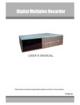
4 Channel Digital Video Recorder
User’s Manual
1
Safety Precautions
CAUTION
RISK OF ELECTRICAL
SHOCK. DO NOT OPEN !
CAUTION: TO REDUCE THE RISK OF ELECTRICAL SHOCK,
DO NOT REMOVE COVER (OR BACK), NO USER
SERVICEABLE PARTS REFER SERVICING TO
QUALIFIED SERVICE PERSONNEL.
The lightning flash with arrowhead symbol, within an equilateral
triangle, is intended to alert the user to the presence of insulated
dangerous Voltage within the product’s enclosure that may be
sufficient magnitude to constitute risk of electrical shock to persons.
The exclamation point within an equilateral triangle is intended to alert
the user to the presence of important operation and maintenance
(servicing) instructions in the literature accompanying the appliance.
WARNING: TO PREVENT FIRE OR SHOCK HAZARD, DO NOT
EXPOSE UNITS NOT SPECIFICALLY DESIGNED FOR
Attention: installation should be performed by qualified service
Personnel only in accordance with the National Electrical Code or
applicable local codes.
Power Disconnect. Units with or without ON-OFF switches have power
supplied to the unit whenever the power cord is inserted into the power
source; however, the unit is operational only when the ON-OFF switch
is the ON position. The power cord is the main power disconnect for all
unites.
Warranty
and Service
There are no serviceable parts for this unit, call for your agent for
details.
2
About this document
Before installing stand alone DVR, be sure to thoroughly review and follow the instructions in this Users
Manual. Pay particular attention to the parts that are marked NOTICE.
Also, when connecting with external application, first turn the power OFF and follow manual
instruction for appropriate installation.
Before reading this document
1. This document is intended for both the administrator and users of stand alone DVR Model.
2. This manual contains information for configuring, managing and using stand alone DVR Model.
3. To prevent fire or electrical shock, do not expose the product to heat or moisture
4. Be sure to read this manual before using stand alone DVR Model.
5. For questions and technical assistance of this product, contact your local dealer.
►Strong recommendation on installation of the DVR unit
1. Check electricity at the place you want to install the DVR unit is stable and meets our electricity
requirements.
Unstable electricity will cause malfunction of the unit or give critical damage to the unit.
2. Several chips on the main board of the DVR unit and hard disk drive inside the unit generate heat, and it
must be properly discharged.
Do not put any objects just beside exhaust port(fan) on the left side of the unit and do not close up an
opening (fresh air in-take) on the right side of the unit..
3. Put the DVR unit at well-ventilated place and do not put heat-generating objects on the unit.
When it is installed inside 19 inch mounting rack together with other devices, please check built-in
ventilation fan of the rack is properly running.
3
FCC Statement:
WARNING
This device complies with Part 15 FCC Rules. Operation is subject to the following two conditions: (1)
This device may not cause harmful interference. (2) This device must accept any interference received
including interference that may cause undesired operation."
* Federal Communications Commission (FCC) Statement
WARNING
This Equipment has been tested and found to comply with the limits for a Class B digital device, pursuant
to Part 15 of the FCC rules. These limits are designed to provide reasonable protection against harmful
interference in a residential installation. This equipment generates, uses and can radiate radio frequency
energy and, if not installed and used in accordance with the instructions, may cause harmful interference
to radio communications. However, there is no guarantee that interference will not occur in a particular
installation. If this equipment does cause harmful interference to radio or television reception, which can
be determined by turning the equipment off and on, the user is encouraged to try to correct the
interference by one or more of the following measures:
- Reorient or relocate the receiving antenna.
- Increase the separation between the equipment and receiver.
- Connect the equipment into an outlet on a circuit different from
that to which the receiver is connected.
- Consult the dealer or an experienced radio/TV technician for help.
* You are cautioned that changes or modifications not expressly
approved by the party responsible for compliance could void your
authority to operate the equipment.
4
Content Table
Safety Precautions………………………………………………….…………………….
2
Content Table……….…………………………………………………………………….. 4
1. Hardware…………………………………………………………………………………… 4
2. Unit Description of Front Panel………………………………………………………….. 5
3. Unit Description of Rear Panel…………………………………………………………… 6
4. Installation……………………..…………………………………………………………… 7
1. Procedure……..……………………………………………………………….… 7
2. Picture…………………………………………………………………………… 9
3. Playback………..………..……………………………………………………… 11
5. Function Setup…………………………………………………………….………………… 13
1. Log-in………..………………….……………………………………………….. 13
2. Basic Operation………………………………………………………………… 14
6. Specifications…………..………………………………………………………………….… 36
7. PTZ Control…………………………..……………………………………………….. …… 38
Hardware
1
X
DVR Machine
1
X
Power Cord
1
X
IDE cable
1
X
Adaptor 12V
1
X
User Manual
1
X
Remote controller
1
X
CD
8
X
Screw (Without Hard Disk)
4
X
Screw (Within one Hard Disk)
5
Unit Description of Front Panel
1 ~ 4 camera channel full screen choose button / 0 ~ 9 password input
Quad screen display button
PIP
Picture in picture button
ZOOM
Picture 2x2 zoom in
POP
Picture on picture button
FREEZE
Picture Freeze
AUTO
Channel auto sequence button
MENU
Function menu button
ESC
Function exit button
LOCK
Key lock button
Value change button
BACKUP
Image backup button
T-SRH
Time search button
PLAY
Image playback button
REC
Image record button
Direction button Up and Down /
Direction button left and right,
Record or playback stop /
Fast / Slow Reverse,
playback pause or step button.
Fast / Slow forward playback.
JOG Shuttle
USB port
Remote controller IR
6
Unit Description of Rear Panel
Power cord in DC 12V, power switcher
75 ohm high and low dips switch / Monitor out
Camera 1 ~ 4 input and
looping output
VGA
Audio channel input x 4 and
output x 2
RS 485 A + / B –
Network connector.
Alarm In: 1 / 2 / 3 / 4
Relay: NO / NC / COM
NOTICE:
VGA connection is not a standard video output of this unit. Call your local dealer for optional purchase.
7
Installation
Procedure
1) Camera Connection
Connect camera to the CAMERA INPUT
located at rear side of the DVR.
2) Monitor Connection (Composite Connection
Method)
Connect monitor to the MONITOR output
located at rear side of the DVR.
3) Sensor Connection
Connect the Sensor to the SENSOR INPUT / OUTPUT at the Rear Panel of the DVR
Relay output : COM+NC, COM+NO
Alarm input : Short-circuit between Alarm1, Alarm2, Alarm3 or Alarm4 and GND is recognized as alarm.
Alarm 1~4 = Camera1~4.
NOTICE: Sensor input is recognized as LOW when alarm signal is on a level with GND, and it is recognized as
HIGH when alarm signal is FLOATING or 5V. Following is internal circuit.
5
V
Internal Circuit
D1
Thus, there is a danger of damage, when the sensor input goes to a Negative level or voltage higher than 5V.
8
4) HDD internal connection
Master x 1
Master x 1 / Slave x 1
Master x 1 / Slave x 1
CD-RW
Master x 1 / Slave x 1
Master x 1 / Master x 1
CD-RW
Master x 1 / Master x 1
Slave x 1 / Slave x 1
Slave x 1 / Slave x 1
Notice:
-Hard Disk Master and Slave jumper pin must be right, otherwise DVR will show fault.
9
5) Power Connection
Connect the power to the POWER
CONNECTION on the Rear Panel of the
system, and turn on the switch.
6) Turn on the POWER.
Make sure the adaptor is 12V
7) Detail setup in SYSTEM SETUP
For detail setup, refer to the instruction of SYSTEM SETUP.
Picture
Full screen or quad screen display
Press
button to display quad screen.
Press numeric 1 / 2 / 3 / 4 buttons to display the desired camera image in full screen.
1.) FREEZE Mode
1. In live and the quad mode press (FREEZE) button to freeze image.
Press again to cancel freeze mode.
2. On the full screen display, press (FREEZE) button to
freeze full screen image.
2.) Zoom Mode 2 x 2 (Display Enlargement.)
Press numeric button to enter full screen mode, then press ZOOM button to enlarge screen.
Use
button to move position.
3.) Auto Mode
Press (AUTO) button to enable channel auto sequencing.
10
4.) PIP (PICTURE IN PICTURE)
1.) Press (PIP) button. Press (AUTO) button to enable screen auto sequencing.
Main picture
Sub picture
2) With
button, select the main channel screen, press
button to select desired camera channel in
small screen.
5.) Watch DOG
DVR will auto reboot if operating system error detected, and then back to normal status.
6.) POP (PICTURE ON PICTURE)
1.) Press POP button to display pictures on screen.
CAMERA 2
CAMERA 3
CAMERA1
CAMERA 4
7.) Alarm Sensor Recording
See the alarm recording setup page 24.
8.) Scheduled Recording
See the scheduled recording setup page 27.
9.) Motion detection Recording
See the motion detection recording setup page 25.
10.) Key Lock function
At Key lock mode, user needs to press lock button to enter password window.
At key lock mode, any button function can not be accessed.
11.) Audio function
4 audio channel recording.
See the advanced setupÆ Record setup (page 27)
11
12.) BACKUP
BACKUP SETUP PAGE
1. BACKUP DEVICE USB FROMAT
2. BACKUP FORMAT
3. BACKUP CHANNEL □1 □2 □3 □4
START: xxxx/xx/xx xx:xx:xx
END: xxxx/xx/xx xx:xx:xx
START BACKUP
BACKUP SIZE: x / MB
FIRST: xxxx/xx/xx xx:xx:xx
LAST: xxxx/xx/xx xx:xx:xx
1.Device USB / CDRW *USB FORMAT
2.Backup format: AVI or PES.
3.Choose channel. v means this camera is selected.
START / END: Backup time range
Size: Current / Total. MB
(Current backup progress MB/ total flash drive size MB)
FIRST / LAST: record time range
Notice
1> Recording is not possible if no camera is connected.
2> PES: All channels record in quad. Use Video Viewer to play back. Screen can display on full channel or
quad. (PES file format is readable by endued AP software only.)
AVI: Record in each channel.
3> Before backup, user needs to stop DVR recording.
4.>To make backup process smooth going recommend using CD-R disk to backup data.
** Multi-used CD disk is not recommend.**
12
Playback
1. Playback rewind Mode
Press (PLAY) button to begin playback.
(System will playback the previous time recording.)
2. T-SRH mode
PLAY SETUP PAGE
1) T-SRH: Playback by time list search.
EVENT LIST
Press T-SRH button to activate playback function.
TIME LIST
Press direction button
FIRST: xxxx/xx/xx xx:xx:xx
UP/DOWN to choose
LAST:
items.
xxxx/xx/xx xx:xx:xx
GOTO: xxxx/xx/xx xx:xx:xx
PLAY GOTO TIME
2) EVENT LIST (Alarm List): Event source- Video loss / Alarm trigger / Motion / Pwreset(DVR reboot)
Key lock / Key unlock / Net login / Net logout
OCCURED
TIME
TYPE
Notice:
Each page contains 12 events recorded; the DVR stores total 1024 events and then rewrite the oldest events
when full.
13
3) TIME LIST (Playback image by Time-Search): Recorded images list (by hours)
TIME SEARCH LIST PAGE
FIRST: xxxx/xx/xx xx:xx:xx (The FIRST date and time recording display).
LAST: xxxx/xx/xx xx:xx:xx (The final date and time recording display).
GOTO: xxxx/xx/xx xx:xx:xx (year / month / day, Hour / Minute / Second)
Press direction button Left/Right to change date and time values position.
Press
values change button to change date and time values.
PLAY GOTO TIME
After date and time input, direction move to PLAY GOTO TIME, press ENTER to start playback.
Notice:
Play speed: Forward / Reverse: 1, 2, 8, 32, 64. Forward slow speed: 1/2, 1/4, 1/8, 1/16.
14
FUNCTION SETUP
LOGIN
1) Press (MENU) button to enter OSD menu. You could do the system function setup in MENU.
2) Password enter window pop-up:
LOGIN DVR SYSTEM
PASSWORD xxxxx
1. Default password (Account-Admin): 00000
2. Default password (Account-User):
11111
3. Default password (Account-User):
22222
4. Default password (Account-User):
33333
5. Default password (Account-GUEST): 44444
3) Press numeric (0 ~ 9)button to enter password.
4) Remote controller function buttons are same as DVR front panel function buttons.
Notice:
1. ADMIN level can setup all DVR menu functions.
2. USER level cannot setup ADVANCED page of DVR main menu function.
3. GUEST level cannot setup DVR menu.
15
Press MENU button to enter MAIN SETUP PAGE.
OSD Operation
MAIN SETUP PAGE
1. HDD INFORMATION
2. DATE-TIME
SETUP
3. DISPLAY
SETUP
4. CAMERA
SETUP
5. BUZZER&RELAY
6. SYSTEM
SETUP
7. PTZ
SETUP
8. ADVANCED
1) Use direction button up/down
SETUP
SETUP
button to select setup item.
2) Press (ENTER)button to enter into sub-menu function setup.
3) Press sub-menu item with direction button up/down
And change the value with
or left/right
button.
values change button or turn inner-shuttle.
4) Press ESC to go back to main / sub menu or exit menu.
16
1. HDD INFORMATION
MAIN SETUP PAGE
NO. SIZE USED BRAND
1. HDD INFORMATION
2. DATE-TIME
SETUP
3. DISPLAY
SETUP
4. CAMERA
SETUP
5. BUZZER&RELAY
6. SYSTEM
7. PTZ
8. ADVANCED
SETUP
SETUP
SETUP
01
080GB OW
SAEGATE
STATUS: USE
START: xxxx(Y)/xx(M)/xx(D) xx:xx:xx(H:M:S)
END: xxxx(Y)/xx(M)/xx(D) xx:xx:xx(H:M:S)
SETUP
Use direction button up/down
button to select HDD INFORMATION item position.
Press ESC to go back to previous menu or exit menu.
>NO: Numbers of hard disk installed.
>Size: Hard disk capacity display. xx GB.
>USED: Hard disk %. If sets overwrite, after hard disk full then starts to overwrite, it displays OW.
Hard full is 99%.
>Brand: DVR system auto detect hard disk brand after power on.
-Status: USE / IDLE
START: xxxx(Y)/xx(M)/xx(D) xx:xx:xx(H:M:S)
The first recording date and time display.
END: xxxx(Y)/xx(M)/xx(D) xx:xx:xx(H:M:S)
The last recording date and time display.
17
2. DATE-TIME SETUP
MAIN SETUP PAGE
DATE-TIME SETUP PAGE
1. HDD INFORMATION
1. HOUR TYPE:
2. DATE-TIME
2. DATE TYPE
SETUP
3. DISPLAY
SETUP
3. DATE 2006 / 01 / 01
4. CAMERA
SETUP
4. TIME
5. BUZZER&RELAY
5. DATE-TIME POSITION SETUP
SETUP
6. SYSTEM
SETUP
7. PTZ
SETUP
8. ADVANCED
SETUP
MENU, ESC:EXIT,
:MODIFY
1. Hour Type: 12H/24H:MM:SS. 12 Hour Format / 24 Hour Format.
2. Date Type: YY/MM/DD, MM/DD/YY, DD/MM/YY, YY/ENG/DD, ENG/DD/YY, DD/ENG/YY, YYYY/MM/DD,
MM/DD/YYYY, DD/MM/YYYY, YYYY/ENG/DD, ENG/DD/YYYY, DD/ENG/YYYY.
Y=Year. M=Month. D=Day. ENG=Month display in English.
01=January; 02=February; 03=March; 04=April; 05=May; 06=June;
07=July; 08= August; 09=September; 10=October; 11=November; 12=December.
3. Date: 2006/01/01. Maximum insert is 2030 years.
4. Time: 12/30/49 > Use direction button up/down choose position, values change button to change date and
time values.
Notice: Please stop REC function first if you want to change the time.
5. Date and Time position setup:
**** DATE-TIME POSITION****
UP
LEFT
RIGHT
DOWN
ENTER for Default
ESC to QUIT
Press direction button UP / DOWN / LEFT / RIGHT to choose items or move date-time position.
Notice: User can see the date-time position moving when pressing direction buttons.
18
3. DISPLAY SETUP
MAIN SETUP PAGE
DISPLAY SETUP PAGE
1. HDD INFORMATION
1. DATE-TIME
2. DATE-TIME
SETUP
2. CAMERA TITLE
3. DISPLAY
SETUP
3. PB DATE-TIME
4. CAMERA
SETUP
5. BUZZER&RELAY
6. SYSTEM
7. PTZ
8. ADVANCED
4. PB CAMERA TITLE
5. DVR STATUS
SETUP
6. VLOSS DISPLAY
SETUP
SETUP
SETUP
MENU, ESC:EXIT,
:MODIFY
Function
Notes
Change
DATE-TIME
Date and Time caption display mode on or off setup.
ON / OFF
CAMERA TITLE
Camera Title caption display mode on or off setup.
ON / OFF
PB DATE-TIME
Playback date and time caption display mode on or off
ON / OFF
setup.
PB CAMERA TITLE
Play back camera title caption display mode on or off
ON / OFF
setup.
DVR STATUS
DVR system, record, playback, audio caption display
ON / OFF
mode on or off setup.
VLOSS DISPLAY
Video loss display
ON / OFF
Press direction button UP / DOWN to choose the desired item.
Press
values change button to change values.
19
4. CAMERA SETUP
MAIN SETUP PAGE
CAMERA SETUP PAGE
1. HDD INFORMATION
2. DATE-TIME
3. DISPLAY
2. TITLE SETUP
SETUP
4. CAMERA
SETUP
5. BUZZER&RELAY
SETUP
6. SYSTEM
1. COLOR SETUP
SETUP
3. MARK&MIRROR SETUP
MENU, ESC: EXIT, ENTER: RUN
SETUP
7. PTZ
SETUP
8. ADVANCED
SETUP
CAMERA COLOR SETUP PAGE
(1.) COLOR SETUP
** CHANNEL NUMBER 01
1. BRIGHTNESS +0
CAMERA SETUP
1. COLOR SETUP
2. TITLE SETUP
3. MARK&MIRROR SETUP
2. CONTRAST
+0
3. SATURATION
+0
4. HUE
+0
5. GAIN
+0
>DEFAULT RESET<
MENU,ESC:EXIT,
CAMERA-COLOR SETUP : Adjust Camera Image
:MODIFY
Function
CHANNEL NUMBER
Select camera
01 ~ 04
BRIGHTNESS
Adjust color brightness
-31~ +32
CONTRAST
Adjust color contrast
-31~ +32
SATURATION
Adjust color saturation
-31~ +32
HUE
Adjust color hue
-31~ +32
GAIN
Adjust color gain
-31~ +32
DEFAULT RESET
Press ENTER button to reset DVR values
Press direction button UP / DOWN to choose items.
Press
values change button to change values.
Notice: Right adjustment of each element in COLOR setup will increase picture quality displayed. We
recommend you to adjust each element of COLOR SETUP for cameras and monitor to be connected to the
DVR unit.
20
(2.) TITLE SETUP: Camera title setup function allows 9 characters for each channel
.
CAMERA TITLE SETUP PAGE
CH1 (CAMERA 01 )
CAMERA SETUP
CH2 (CAMERA 02 )
1. COLOR SETUP
CH3 (CAMERA 03 )
2. TITLE SETUP
CH4 (CAMERA 04 )
3. MARK&MIRROR SETUP
MENU, ESC: EXIT:
: MODIFY
Press direction button UP / DOWN / LEFT / RIGHT to choose items and position.
Press
values change button to change values.
Notice:
Characters selection sequence:
Numeric: 0 / 1 / 2 / 3 / 4 / 5 / 6 / 7 / 8 / 9
Capital letter: A / B / C / D / E / F / G / H / I / J / K / L / M / N / O / P / Q / R / S / T / U / V / W / X / Y / Z
SPACE
21
3.)MASK&MIRROR SETUP
MASK&MIRROR SETUP PAGE
**MASK FUNCTION
CAMERA SETUP
1. CH 1: OFF
1. COLOR SETUP
2. CH 2: OFF
2. TITLE SETUP
3. CH 3: OFF
3. MARK&MIRROR SETUP
4. CH 4: OFF
OFF
**MIRROR FUNCTION OFF
1. CH 1: OFF
2. CH 2: OFF
3. CH 3: OFF
4. CH 4: OFF
MASK&MIRROR SETUP PAGE
**Channel MASK FUNCTION
OFF / ON
1. CH 1: OFF / ON
2. CH 2: OFF / ON
3. CH 3: OFF / ON
4. CH 4: OFF / ON
**Image MIRROR FUNCTION OFF / ON
1. CH 1: OFF / ON
2. CH 2: OFF / ON
3. CH 3: OFF / ON
4. CH 4: OFF / ON
Press direction button UP / DOWN / LEFT / RIGHT to choose items and position.
Press
values change button to change values.
22
5. BUZZER&RELAY SETUP
BUZZER&RELAY SETUP PAGE
MAIN SETUP PAGE
BUTTON TONE
ON
1. HDD INFORMATION
**SYSTEM BUZZER
OFF
2. DATE-TIME SETUP
1. ALARM BUZZER
ON
3. DISPLAY
SETUP
2. MOTION BUZZER
ON
4. CAMERA
SETUP
3. VLOSS BUZZER
5. BUZZER&RELAY
6. SYSTEM
SETUP
SETUP
7. PTZ
SETUP
8. ADVANCED SETUP
ON
**SYSTEM RELAY
N.O.
1. ALARM RELAY
ON
2. MOTION RELAY
ON
3. VLOSS RELAY
ON
MENU, ESC: EXIT:
BUTTON TONE ON / OFF
**SYSTEM BUZZER: Buzzer function
>ON / OFF
1. ALARM BUZZER:
> ON / OFF
2. MOTION BUZZER:
> ON / OFF
3. VLOSS BUZZER:
> ON / OFF
**SYSTEM RELAY N.O. / N.C.
1. ALARM RELAY:
> ON / OFF
2. MOTION RELAY:
> ON / OFF
3. VLOSS RELAY:
> ON / OFF
Press direction buttons UP / DOWN to BUZZER SETUP items.
Press values change button to change values.
23
: MODIFY
6. SYSTEM SETUP
MAIN SETUP PAGE
SYSTEM SETUP PAGE
1. HDD INFORMATION
1. DWELL INTERVAL 010SEC
2. DATE-TIME SETUP
3. DISPLAY
SETUP
4. CAMERA
SETUP
5. BUZZER&RELAY
6. SYSTEM
SETUP
SETUP
7. PTZ
SETUP
8. ADVANCED SETUP
2. LANGUAGE
ENGLISH
3. RS-485 ID
01
4. RS-485 BAUDRATE 9600
5. LIVE AUDIO
MENU, ESC: EXIT:
OFF
: MODIFY
SYSTEM SETUP PAGE
1. DWELL INTERVAL:
- 0 ~ 999SEC
2. LANGUAGE:
- English / Chinese / French / Japanese / Spanish / German
3. RS-485 ID:
-01 ~ 16
4. RS-485 BAUDRATE:
- 9600 / 4800 / 2400
5. LIVE AUDIO
- CH01 ~ CH04 / OFF
Notice: RS 485
1. RS-485 ID and baud rate is the command for system control keyboard. If user does not connect this DVR
with control keyboard then ignore this setup.
Notice: LIVE AUDIO
1. On quad or full screen, user needs to select channel live output.
2. But on playback mode, this function is no used. Users need to choose channel output. That means just press
channel button to playback audio.
Press direction buttons UP/DOWN to choose items.
Press values change button to change values.
24
7. PTZ SETUP
MAIN SETUP PAGE
PTZ SETUP PAGE
1. HDD INFORMATION
**PROTOCOL
P-TYPE
2. DATE-TIME SETUP
**BAUDRATE
2400
3. DISPLAY
SETUP
**CHANNEL NUMBER CH01
4. CAMERA
SETUP
PTZ NUMBER
5. BUZZER&RELAY
LINE SCAN
SETUP
6. SYSTEM
SETUP
ALARM
7. PTZ
SETUP
ALARM ID
01
OFF
ZOOM PERIOD
8. ADVANCED SETUP
TEST
PTZ SETUP PAGE
**PROTOCOL
P-TYPE / D-TYPE
**BAUDRATE
2400 / 4800 / 9600
**CHANNEL NUMBER CH01 ~ CH04
PTZ NUMBER
01 ~ 64
LINE SCAN
OFF / ON
ALARM
OFF / ON
ALARM ID
01 ~ 04 (Alarm trigger)
ZOOM PERIOD
1 ~ 999 SEC
TEST: This function is to simulate if the PTZ dome is connected correctly or not. If yes, the PTZ dome will
activate when enter this menu.
Press direction buttons UP / DOWN to choose items.
Press values change button to change values.
PS: User has to set up P1, P2 (preset point). Present 2 is the preset point for alarm event, after duration time,
the camera lens return to P1 preset point. For detail setting please refer to the DVR PTZ control description.
25
8. ADVANCED SETUP
ADVANCED SETUP PAGE
MAIN SETUP PAGE
1. ALARM SETUP
1. HDD INFORMATION
2. MOTION SETUP
2. DATE-TIME SETUP
3. DISPLAY
SETUP
4. CAMERA
SETUP
5. BUZZER&RELAY
6. SYSTEM
7. PTZ
3. RECORD SETUP
4. EVENT RECORD SETUP
5. PASSWORD SETUP
SETUP
6. NETWORK SETUP
SETUP
7. HDD FORMAT
SETUP
8. FACTORY DEFAULT
8. ADVANCED SETUP
9. UPGRADE
ADVANCED SETUP PAGE
ALARM SETUP PAGE
1. ALARM SETUP
1. ALARM FUNCTION
2. MOTION SETUP
2. ALARM POPUP
ON / OFF
ON / OFF
3. RECORD SETUP
4. EVENT RECORD
>ALARM POLARITY SETUP<
5. PASSWORD SETUP
ALARM01: NO / NC / OFF
6. NETWORK SETUP
ALARM02: NO / NC / OFF
7. HDD FORMAT
ALARM03: NO / NC / OFF
8. FACTORY DEFAULT
ALARM04: NO / NC / OFF
9. UPGRADE
MENU, ESC: EXIT:
ALARM POLARITY SETUP PAGE
ALARM01: NO / NC / OFF
ALARM02: NO / NC / OFF
1. ALARM FUNCTION
ON / OFF
2. ALARM POPUP
ON / OFF
ALARM03: NO / NC / OFF
ALARM04: NO / NC / OFF
Press direction buttons up/down to choose items.
Press values change button to change values.
Notice: ALARM POPUP
Event channel jump to full screen when alarm triggered.
26
: MODIFY
2. MOTION SETUP
ADVANCED SETUP PAGE
MOTION SETUP PAGE
1. ALARM SETUP
**MOTION FUNCTION ON
2. MOTION SETUP
**CHANNEL NUMBER CH01
3. RECORD SETUP
1. FRAME NUMBER 03
4. EVENT RECORD
2. SENSITIVITY
5. PASSWORD SETUP
3. MOTION ACTIVE
6. NETWORK SETUP
4. MOTION AREA SETUP
010
ON
7. HDD FORMAT
MENU, ESC: EXIT:
8. FACTORY DEFAULT
: MODIFY
9. UPGRADE
MOTION SETUP PAGE
**MOTION FUNCTION (For all channels)
-ON / OFF
**CHANNEL NUMBER
-01 ~ 04
1. FRAME NUMBER
Number of the block squares should larger than the number set up in frame number. If smaller, the record
mode will not be active.
-1 ~ 15
2. SENSITIVITY Adjusts motion Detection Sensitivity.
-1 ~ 15
3. MOTION ACTIVE (For each channel)
-ON / OFF
4. MOTION AREA SETUP
Press direction buttons UP / DOWN to choose items.
Press values change button to change values.
27
> MOTION AREA SETUP < (Press LOCK button for help)
****CH01 AREA MASK****
: WALK ON MODE
Press 1/2/3/4 numeric to select channel.
Press
value change button to change mode.
1.2.3.4: SELECT CHANNEL
Press direction button to move cursor.
: MOVE CURSOR
Press ENTER button to on mask function or off.
ENTER KEY: MASK OFF
Press ESC button to quit.
ESC KEY: QUIT
WALK ON MODE: Set up single sections one by one mode ON(SELECT).
WALK OFF MODE: Set up single sections one by one mode OFF(CLEAR).
BLOCK ON MODE: Select by BLOCK area mode ON(SELECT).
BLOCK OFF MODE: Select by BLOCK area mode OFF(CLEAR).
ALL ON MODE: Select all area mode ON(SELECT).
ALL OFF MODE: Select all area mode OFF(CLEAR).
WALK ON MODE
WALK OFF MODE. Press ENTER to clear or select each sections.
BLOCK ON MODE
BLOCK OFF MODE. Press ENTER to clear or select sections by block.
ALL ON MODE
ALL OFF MODE Press ENTER to clear or select all sections.
28
3. RECORD SETUP
RECORD SETUP PAGE
ADVANCED SETUP PAGE
1. RECORD TYPE FIELD
1. ALARM SETUP
2. HDD FULL
2. MOTION SETUP
3. RECORD SCHEDULE
3. RECORD SETUP
4. RECORD START
4. EVENT RECORD
5. RESOLUTION
5. PASSWORD SETUP
6. AUDIO RECORD
6. NETWORK SETUP
7. SCHEDULE SETUP
7. HDD FORMAT
8. RECORD SPEED SETUP<
OVERWRITE
8. FACTORY DEFAULT
9. UPGRADE
MENU, ESC: EXIT:
: MODIFY
RECORD SETUP PAGE
1)
RECORD TYPE : FIELD / CIF
2)
HDD FULL: This feature is to command DVR to OVERWRITE or STOP recording when HDD is full.
-OVERWRITE / STOP REC
3)
RECORD SCHEDULE: Time SCHEDULE record mode is on or off.
-ON / OFF
4)
RECORD START: Always record after power on.
-ON / OFF
5)
RESOLUTION: Record image quality setup
- SUPER / HIGH / FINE / NORMAL / LOW
6)
AUDIO RECORD: Audio sound effect records to hard disk.
-ON / OFF
7)
SCHEDULE SETUP
8)
RECORD SPEED SETUP
Press direction buttons UP / DOWN to choose items.
Press values change button to change values.
Notice:
Normal record is Independent. It will not in conflict with event record.
29
>SCHEDULE SETUP<
RECORD SETUP
1. RECORD TYPE FIELD
2. HDD FULL
Press direction buttons to choose
OVERWRITE
SCHEDULE items.
3. RECORD SCHEDULE
4. RECORD START
Press values change button to increase or reduce
5. RESOLUTION
6. AUDIO RECORD
7. SCHEDULE SETUP
8. RECORD SPEED SETUP
SCHEDULE SETUP
CURSOR STEP
30MIN / 5MIN
SUN
MON
TUE
WED
THU
FRI
SAT
Press direction buttons UP / DOWN / LEFT / RIGHT to see
date and time difference.
Press values change LEFT / RIGHT button to change 30MIN or 5 MIN.
30
30MIN
SCHEDULE SETUP
CURSOR STEP
SUN
00:00 01:00 02:00 03:00 04:00 05:00 06:00 07:00 08:00 09:00 10:00 11:00 12:00 13:00 14:00 15:00 16:00 17:00 18:00 19:00 20:00 21:00 22:00 23:00
00:30 01:30 02:30 03:30 04:30 05:30 06:30 07:30 08:30 09:30 10:30 11:30 12:30 13:30 14:30 15:30 16:30 17:30 18:30 19:30 20:30 21:30 22:30 23:30
MON
00:00 01:00 02:00 03:00 04:00 05:00 06:00 07:00 08:00 09:00 10:00 11:00 12:00 13:00 14:00 15:00 16:00 17:00 18:00 19:00 20:00 21:00 22:00 23:00
00:30 01:30 02:30 03:30 04:30 05:30 06:30 07:30 08:30 09:30 10:30 11:30 12:30 13:30 14:30 15:30 16:30 17:30 18:30 19:30 20:30 21:30 22:30 23:30
TUE
00:00 01:00 02:00 03:00 04:00 05:00 06:00 07:00 08:00 09:00 10:00 11:00 12:00 13:00 14:00 15:00 16:00 17:00 18:00 19:00 20:00 21:00 22:00 23:00
00:30 01:30 02:30 03:30 04:30 05:30 06:30 07:30 08:30 09:30 10:30 11:30 12:30 13:30 14:30 15:30 16:30 17:30 18:30 19:30 20:30 21:30 22:30 23:30
WED
00:00 01:00 02:00 03:00 04:00 05:00 06:00 07:00 08:00 09:00 10:00 11:00 12:00 13:00 14:00 15:00 16:00 17:00 18:00 19:00 20:00 21:00 22:00 23:00
00:30 01:30 02:30 03:30 04:30 05:30 06:30 07:30 08:30 09:30 10:30 11:30 12:30 13:30 14:30 15:30 16:30 17:30 18:30 19:30 20:30 21:30 22:30 23:30
THU
00:00 01:00 02:00 03:00 04:00 05:00 06:00 07:00 08:00 09:00 10:00 11:00 12:00 13:00 14:00 15:00 16:00 17:00 18:00 19:00 20:00 21:00 22:00 23:00
00:30 01:30 02:30 03:30 04:30 05:30 06:30 07:30 08:30 09:30 10:30 11:30 12:30 13:30 14:30 15:30 16:30 17:30 18:30 19:30 20:30 21:30 22:30 23:30
FRI
00:00 01:00 02:00 03:00 04:00 05:00 06:00 07:00 08:00 09:00 10:00 11:00 12:00 13:00 14:00 15:00 16:00 17:00 18:00 19:00 20:00 21:00 22:00 23:00
00:30 01:30 02:30 03:30 04:30 05:30 06:30 07:30 08:30 09:30 10:30 11:30 12:30 13:30 14:30 15:30 16:30 17:30 18:30 19:30 20:30 21:30 22:30 23:30
SAT
00:00 01:00 02:00 03:00 04:00 05:00 06:00 07:00 08:00 09:00 10:00 11:00 12:00 13:00 14:00 15:00 16:00 17:00 18:00 19:00 20:00 21:00 22:00 23:00
00:30 01:30 02:30 03:30 04:30 05:30 06:30 07:30 08:30 09:30 10:30 11:30 12:30 13:30 14:30 15:30 16:30 17:30 18:30 19:30 20:30 21:30 22:30 23:30
Example: TUE ~ SAT, all day schedule time recording, but SUN 07:00 ~ 22:00 and MON 01:30 ~ 11:30
do schedule recording. User can press ENTER to see the schedule time area difference.
Schedule record mode, on the live mode, an “O” would shows on the left top of screen.
There are 3-color display and represent different modes of recording as following.
GREEN: Schedule record mode.
YELLOW: Schedule record starts.
WHITE: User press direction key “DOWN” to pause schedule record. Press again to start record.
31
>RECORD SPEED SETUP<
RECORD SETUP
1. RECORD TYPE FIELD
2. HDD FULL
OVERWRITE
3. RECORD SCHEDULE
4. RECORD START
5. RESOLUTION
6. AUDIO RECORD
7. SCHEDULE SETUP
RECORD SPEED SETUP PAGE
TOTAL SPEED: FULL / HALF / 20 fps / 10 fps / 4 fps
CH 01: ON
CH 02: ON
CH 03: ON
CH 04: ON
8. RECORD SPEED SETUP
RECORD SPEED SETUP PAGE
TOTAL SPEED:
Field: FULL / HALF / 20 fps / 10 fps / 4 fps (NTSC), FULL / HALF / 24 fps / 16 fps / 8 fps (PAL)
CIF: FULL / HALF / 40 fps / 20 fps / 8 fps (NTSC), FULL / HALF / 32 fps / 16 fps / 8 fps (PAL)
CH 01: ON / OFF
CH 02: ON / OFF
CH 03: ON / OFF
CH 04: ON / OFF
Press direction buttons UP / DOWN to choose items.
Press values change button to change values.
Notice:
Normal recording is independent. It will not in conflict with event record.
32
4. EVENT RECORD
ADVANCED SETUP PAGE
1. ALARM SETUP
EVENT RECORD SETUP PAGE
2. MOTION SETUP
1. EVENT MOTION
OFF
3. RECORD SETUP
2. EVENT ALARM
OFF
4. EVENT RECORD
3. EVENT DURATION 0 10 SEC
5. PASSWORD SETUP
4. RECORD SPEED
6. NETWORK SETUP
5. RECORD RESOULTION NORMAL
7. HDD FORMAT
6. PRIORITY RECORD OFF
8. FACTORY DEFAULT
7. PRE-ALARM RECORD ON
9. UPGRADE
8. EVENT LOG SETUP OFF
1. EVENT MOTION
-OFF / ON
2. EVENT ALARM
-OFF / ON
FULL
3. EVENT DURATION 0 -10 SEC (01 ~ 999)
4. RECORD SPEED
(Independent)
Field: FULL / HALF / 20 fps / 10 fps / 4 fps (NTSC), FULL / HALF / 16 fps / 8 fps / 4 fps (PAL)
CIF: FULL / HALF / 40 fps / 20 fps / 8 fps (NTSC), FULL / HALF / 32 fps / 16 fps / 8 fps (PAL)
5. RECORD RESOULTION -SUPER / HIGH / FINE / NORMAL / LOW (Independent)
6. PRIORITY RECORD –OFF / OFF
7. PRE-ALARM RECORD –ON / OFF ( 5 seconds)
8. EVENT LOG SETUP – ON/OFF
EVENT SETUP PAGE
Press direction buttons
UP / DOWN / LEFT / RIGHT
to choose items.
Press values change button
to change values.
1. MOTION EVENT
ON
2. ALARM EVENT
ON
3.VLOSS EVENT
ON
4.SYSTEM EVENT
ON
1. MOTION EVENT
ON/OFF
2. ALARM EVENT
ON/OFF
3. VLOSS EVENT
ON/OFF
4. SYSTEM EVENT
ON/OFF
Notice:
Event recording is Independent. It will not in conflict with normal record.
33
5. PASSWORD SETUP
ADVANCED SETUP PAGE
1. ALARM SETUP
PASSWORD SETUP PAGE
2. MOTION SETUP
1. PASSWORD AUTH
3. RECORD SETUP
2. REMOTE CONTROL
4. EVENT RECORD
3. ADMIN (00000)
5. PASSWORD SETUP
4. USER1 (11111)
6. NETWORK SETUP
5. USER2 (22222)
7. HDD FORMAT
6. USER3 (33333)
8. FACTORY DEFAULT
7. GUEST (44444)
9. UPGRADE
PASSWORD SETUP PAGE
1. PASSWORD AUTH
ON / OFF
2. REMOTE CONTROL
ON / OFF
3. ADMIN (00000)
4. USER1 (11111)
5. USER2 (22222)
6. USER3 (33333)
7. GUEST (44444)
Press direction buttons UP / DOWN / LEFT / RIGHT to choose items position.
User press 0 ~ 9 numeric to choose password.
Notice:
1. ADMIN level can setup all DVR menu functions.
2. USER level cannot setup ADVANCED page of DVR main menu function.
3. GUEST level cannot access to DVR menu.
4. REMOTE CONTROL:
ON: Network management has authority to control DVR.
OFF: Network management and user have no authority to control DVR.
PS. DVR management authorization is higher than network management.
34
6. NETWORK SETUP
ADVANCED SETUP PAGE
STATIC IP SETUP PAGE
1. ALARM SETUP
1.NETWORK FUNCTION
2. MOTION SETUP
2. SMTP SETUP
3. RECORD SETUP
3. PORT
4. EVENT RECORD
4. TYPE STATIC IP CON
5. PASSWORD SETUP
IP: xxx.xxx.xxx.xxx
6. NETWORK SETUP
MASK: xxx.xxx.xxx.xxx
7. HDD FORMAT
GATE WAY:xxx.xxx.xxx.xxx
8. FACTORY DEFAULT
DNS:xxx.xxx.xxx.xxx
9. UPGRADE
STATIC IP SETUP PAGE
1. NETWORK FUNCTION : ON / OFF. Needs to keep on, if network uses.
2. SMTP
Press direction buttons UP / DOWN / LEFT / RIGHT
SMTP SETUP PAGE
to choose items position.
1. FUNCTION: ON / OFF
Press values change button or numeric key to change values.
2. MAIL SERVER:
3. USER NAME
4. PASSWORD
5. EMAIL ADDRESS
TEST : Send a mail to mail account for testing.
3. PORT: 00080. Depends on network system. Usually is 80.
4. TYPE STATIC IP CON.
-Using direction button to move on here, using value change button to choose STATIC IP.
IP :
MASK:
xxx.xxx.xxx.xxx
xxx.xxx.xxx.xxx
GATE WAY: xxx.xxx.xxx.xxx
DNS:
xxx.xxx.xxx.xxx
- Input all IP information base on LAN or WAN.
Notice:
After IP information input, go back to 4. TYPE STATIC IP CON. Choose CON. And then press ENTER to load.
If correct, Network connecting shows under screen.
PPPOE: USER NAME / PASSWORD / DNS
DYNAMIC IP: Local network IP auto detect.
35
7. HDD FORMAT
ADVANCED SETUP PAGE
1. ALARM SETUP
2. MOTION SETUP
Press direction buttons UP / DOWN to
3. RECORD SETUP
HDD FORMAT items position.
4. EVENT RECORD
Press ENTER to format all HDD.
5. EVENT
6. PASSWORD SETUP
Caution: User can format HDD only when
7. HDD FORMAT
all HDD stop record or playback.
8. FACTORY DEFAULT
9. UPGRADE
Æ HDD FORMAT CAUTION!! :
**FORMAT CAUTION**
Press ENTER button to format hard disk.
ALL DATA IN STORAGE DEVICE WILL BE
DESTROYED!!
PRESS [ENTER] TO FORMAT ALL HDD.
Press ESC button to cancel hard disk format
PRESS [ENTER] TO FORMAT NEW HDD.
PRESS [ESC] TO CANCEL.
**PLEASE WAIT, HDD FORMATING.
**HDD FORMAT, COMPLETED.
36
8. FACTORY DEFAULT
ADVANCED SETUP PAGE
1. ALARM SETUP
2. MOTION SETUP
Press direction buttons UP / DOWN to
3. RECORD SETUP
FACTORY DEFAULT items position.
4. EVENT RECORD
Press ENTER to restore.
5. EVENT
6. PASSWORD SETUP
7. HDD FORMAT
8. FACTORY DEFAULT
9. UPGRADE
** CAUTION!!**
ALL SETUP VALUE WILL BE CHANGE.
Press ENTER button to restore.
PRESS [ENTER] TO RESTORE DEFAULT.
PRESS [BKUP] TO BACKUP CONFIG.
Press ESC button to cancel.
PRESS [TSH] TO RESTORE FROM FILE.
PRESS [ESC] TO CANCEL.
9. UPGRADE. USB / CD-R disk selection.
ADVANCED SETUP PAGE
**UPGRADE**
1. ALARM SETUP
DVR VER: x.x.xx
2. MOTION SETUP
FILE VER: x.x.xx
3. RECORD SETUP
ENTER: START UPGRADE
4. EVENT RECORD
ESC:
EXIT UPGRADE
5. EVENT
6. PASSWORD SETUP
7. HDD FORMAT
**UPGRADE**
8. FACTORY DEFAULT
NO USB
9. UPGRADE
ESC: EXIT
Notice:
Do not power off or remove flash drive when system update.
37
Specification and configuration
Model
4 CH DVR
Video I/F
NTSC / PAL Auto Detection
Input
4 CH inputs 1.0Vp-p, 75ohm unbalanced (BNC Type)
Output
Main monitor Composite (BNC),
4 looping output (BNC)
S/N Ratio
More than 40dB
Color
6.7 Million
Monitoring Method
Display Screen
1, 4 CH, PIP, 2 x Zoom, Freeze
Zoom
Live & PB Available, 2 x 2 zoom
Sequence
Available
Screen Quality
Full: 720(H) x 480(V) Active Pixels (NTSC);
720(H) x 576(V) Active Pixels (PAL)
1/4 Screen: 360(H) x 240(V) Active Pixels (NTSC);
360(H) x 288(V) Active Pixels (PAL)
Display Rate
120 frames
Recording/ Play Function
Recording (Max)
Field: FULL / HALF/ 20 fps / 10 fps / 4 fps
CIF: FULL / HALF / 40 fps / 20 fps / 8 fps
Record Quality
Super, High, Fine, Normal, Low
Compressed Picture
MPEG4
Picture Recording Method
CIF / Field
REC. Mode
Playback Mode
Time-Lapse / Event
Date/ Time search or event search
Other Function
Operation Mode
Triplex (Record / Playback / Network)
Watch DOG
Available
Motion Detect Area
16 x12, ON/OFF sector selectable.
Motion detect recording
Alarm
4 alarm In / 1 relay Out
Back-Up
USB, Flash Drive. (Card reader + CF is not supported.)
RS485
For control keyboard
Storage
4 IDE HDD (maximum)
Audio Input
RCA x 4
Audio Output
RCA x 1
VGA Output
VGA x 1 (optional)
38
Mechanical
IR Remote Controller
Standard
JOG Shuttle
X1
Power Supply
DC 12V / 5 A if hard disk x 2 installed
DC 12V / 8.33 A if hard disk x 3 or x 4 installed
Weight
Dimension
N.W.:7.3 kg
430 (W) x 360 (D) x 72.6 (H) mm
Operating Temperature
41° F~104° F (5° C~+40° C)
Operating Humidity
Less than 90%
39
DVR control PTZ dome (User needs to login if password protection is on)
KAY 0 : To PTZ control mode.
KEY 1 ~ 4 : Select camera.
KEY 5: Exit preset function.
KEY6 ~ KEY 9 / (Preset 1 ~ Preset 4): To preset position then preset setup mode on. (4 Preset setup support.)
KEY QUAD: Set the preset position.
Example:
1. Set preset 1, key 6, (P1) shows on right-up screen. Then move PTZ dome to any position wants. Key QUAD
to finished. (P1)
2. Set preset 3, key 8, (P3) shows on right-up screen. Then move PTZ dome to any position wants. Key QUAD
to finished. (P3)
KEY ZOOM: 2 functions.
1: ZOOM IN / 2.To PTZ OSD menu item select.
KEY FREEZE: 2 functions. 1: ZOOM OUT / 2.To PTZ OSD item value select.
KEY AUTO: A to B LINE SCAN
KEY MENU: To PTZ MENU OSD function
KEY ESC:IRIS OPEN
KEY LOCK:IRIS CLOSE
KEY +: Set LINE SCAN left side point.
KEY -: Set LINE SCAN right side point.
KEY PLAY: FOCUS NEAR
KEY REC: FOCUS FAR
KEY UP / DOWN / LEFT / RIGHT: Control PTZ moving.
40
Record Time Table: 80 GB HD (Approximate Time Table)
Record Quality: Low
FPS
Full
Half
20
10
4
Hours
163 hr
243 hr
280 hr
379 hr
520 hr
Record Quality: Normal
FPS
Full
Half
20
10
4
Hours
113
194 hr
253 hr
357 hr
506 hr
FPS
Full
Half
20
10
4
Hours
62 hr
114 hr
158 hr
260 hr
423 hr
Record Quality: Fine
Record Quality: High
FPS
Full
Half
20
10
4
Hours
51 hr
96 hr
132 hr
225 hr
387 hr
Record Quality: Super
FPS
Full
Half
20
10
4
Hours
42 hr
79 hr
113 hr
197 hr
357 hr
Actual recording time is base on live environment. This table is only for reference.
41
Network and USB data read
1. In CD ROM, double click setup.exe to access software installation.
2. Suggest computer system up to PIV 2.0 GHz , RAM up to 256 MB , VGA card up to 64M.
Windows XP / 2000.
3. Close Microsoft NetMeeting if it is running. And then restart client viewer.
4. Make sure the VGA card driver is originally from VGA manufacturer.
5. Make sure Microsoft DirectX 9.0b is installed.
6. Make sure IE all ActiveX item are all on.
Input user’s name / password / DVR IP Address / DVR Port according your LAN or WAN system.
Press OK to login. Press cancel to quit if user is not going to view through LAN or WAN.
Or go in AP to view PES from backup in USB device.
42
FUNCTION BUTTON:
Click Live to view image.
B.
C.
D.
A.
A.
C.
1. Live: to live mode.
REC: live record button.
2. Download: to playback mode.
Setting: record path setup button.
3. File Play: to file play mode.
Capture: image capture button (.bmp).
4. PTZ: to PTZ dome mode
Event: event list.
Setting: DVR function setup.
B.
D.
1. Live: Live mode status.
1 ~ 4 full screen display.
2. File: File mode status.
Quad mode display.
3. Event: Event mode status.
4. D.L.: Play back mode status.
5. Net: Network connecting status.
43
Download: press download to playback mode.
DVR REC Start: DVR record start time.
DVR REC End: DVR record end time.
Start: choose playback start time.
End: choose playback end time.
** Last one minute display.**
CH 1 ~ CH 4: choose camera.
Press Count button to calculate data size.
44
After data count, press OK to start playback.
Playback data auto save to REC path.
45
Record path setup: .ps file saved.
REC: press REC button to record live image.
46
Capture: Capture image file to .bmp saved. Only live and file play acceptable.
Press Setting to DVR function setup: 1. SYSTEM 2. REC 3. ALARM / MOTION.
1. System
47
2. REC
3. ALARM / MOTION
48
Event: Event list playback. Only alarm and motion playback.
Choose event time, click OK to start playback.
49
Press File Play to data backup play mode. Click Open to choose file.
Choose path and file name and then ready to play mode.
50
Press Play to start back up data playback mode.
For the setting details please refer to the remark on page 25 / 40 of the P/T/Z dome mode.
Click PTZ button to control mode, and then select channel 1 ~ channel 4 which is corresponding to PTZ dome
PTZ Control function:
Click the left button of mouse on direction arrowhead, on each click, the PTZ dome will move 16 +/- 4 degree.
The Numeral presents for camera channel not PTZ ID.
51
Memo
52