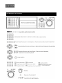
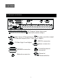
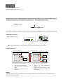
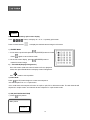
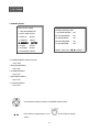
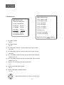
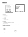
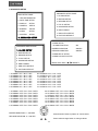
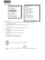
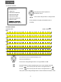
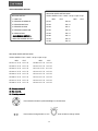
1
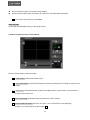
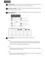
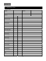
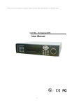
Thank you for purchasing our product. Please read this User’s Manual before using the product. Change without Notice 16 Channel Digital Video Recorder User’s Manual 1 Safety Precautions CAUTION RISK OF ELECTRICAL SHOCK. DO NOT OPEN ! CAUTION: TO REDUCE THE RISK OF ELECTRICAL SHOCK, DO NOT REMOVE COVER (OR BACK), NO USER SERVICEABLE PARTS REFER SERVICING TO QUALIFIED SERVICE PERSONNEL. This label may appear on the bottom of the unit due to space limitations. The lightning flash with arrowhead symbol, within an equilateral triangle, is intended to alert the user to the presence of insulated dangerous Voltage within the product’s enclosure that may be sufficient magnitude to constitute risk of electrical shock to persons. The exclamation point within an equilateral triangle is intended to alert the user to the presence of important operation and maintenance (servicing) instructions in the literature accompanying the appliance. WARNING: TO PREVENT FIRE OR SHOCK HAZARD, DO NOT EXPOSE UNITS NOT SPECIFICALLY DESIGNED FOR Attention: installation should be performed by qualified service Personnel only in accordance with the National Electrical Code or applicable local codes. Power Disconnect. Units with or without ON-OFF switches have power supplied to the unit whenever the power cord is inserted into the power source; however, the unit is operational only when the ON-OFF switch is the ON position. The power cord is the main power disconnect for all unites. “CAUTION: Danger of explosion if battery is incorrectly replaced. Replace only with the same or equivalent type recommended by the manufacturer. Dispose of used batteries according to the manufacturer‘s instruction.” Warranty and Service During the warranty period (one year for Hard Disk), we will repair or replace the hard disk free of charge. Be sure to have the model number, serial number and vendor stick on hard disk for service representative. 2 About this document Before installing stand alone DVR, be sure to thoroughly review and follow the instructions in this Users Manual. Pay particular attention to the parts that are marked NOTICE. Also, when connecting with external application, first turn the power OFF and follow manual instruction for appropriate installation. Before reading this document 1. This document is intended for both the administrator and users of stand alone DVR Model. 2. This manual contains information for configuring, managing and using stand alone DVR Model. 3. To prevent fire or electrical shock, do not expose the product to heat or moisture 4. Be sure to read this manual before using stand alone DVR Model. 5. For questions and technical assistance of this product, contact your local dealer. ►Strong recommendation on installation of the DVR unit 1. Check electricity at the place you want to install the DVR unit is stable and meets our electricity requirements. Unstable electricity will cause malfunction of the unit or give critical damage to the unit. 2. Several chips on the main board of the DVR unit and hard disk drive inside the unit generate heat, and it must be properly discharged. Do not put any objects just beside exhaust port(fan) on the left side of the unit and do not close up an opening (fresh air in-take) on the right side of the unit.. 3. Put the DVR unit at well-ventilated place and do not put heat-generating objects on the unit. When it is installed inside 19 inch mounting rack together with other devices, please check built-in ventilation fan of the rack is properly running. 3 Content Table Safety Precautions………………………………………………………………………………………………. 2 About this document……………………………………………………………………………………………. 3 Content Table……………………………………………………………………………………………………. 4 Unit Description of Front Panel………………………………………………………………………………… 5 Unit Description of Rear Panel…………………………………………………………………………………. 6 Installation……………………………………………………………………………………………………….. 7 Procedure………………………………………………………………………………………………….. 7 Picture……………………………………………………………………………………………………… 10 Playback………………………………………………………………………………………………….. 12 Function Setup………………………………………………………………………………………………….. 14 Login………………………………………………………………………………………………………. 14 Basic Operation………………………………………………………………………………………….. 15 1. HDD Information…………………………………………………………………………………. 16 2. Date-Time Setup………………………………………………………………………………… 17 3. Display Setup……………………………………………………………………………………. 18 4. Camera Setup………………………………………………………………………………….. 19 5. Buzzer Setup……………………………………………………………………………………. 23 6. Audio Setup……………………………………………………………………………………… 24 7. System Setup……………………………………………………………..…………………….. 25 8. Advanced Setup………………………………………………………………………………… 26 HDD Bay………………………………………………………………………………………………………… 38 Specification and configuration……………………………………………………………………………….. 40 Remote Viewer………………………………………………………………………………………………… 43 Configuration Chart……………………………………………………………………………………………. 48 4 Unit Description of Front Panel 5 Unit Description of Rear Panel 16 Cha nnel Vid eo Inp ut a nd m a in/c a ll m onitor outp ut Y/C vid eo m onitor outp ut Aud io Inp ut. 2 Cha nnel Inp ut, 1 Cha nnel Outp ut (Out 1: Left, Out 2: Rig ht) RS 232 c onnec tor 75 Ohm Hig h / Low Ad just Ala rm c onnec tor HDD BAY c onnec tor Control keyb oa rd c onnec tor Network c onnec tor Power In / Power switc her 6 Installation Procedure 1) Camera Connection DC LEVEL Connect the camera to the CAMERA INPUT V.P CH1 CH2 CH3 CH4 CH1 CH2 CH3 CH4 VIDEO DC MONITOR on the Rear Panel of the 16 CH DVR. VIDEO LENS AC24V/DC12 Rear part of CAMERA 2) Monitor Connection (Composite Connection Method) Connect the monitor to the MONITOR OUT on CH1 CH2 CH3 CH4 CH1 CH2 CH3 CH4 MONITOR the Rear Panel of the 16 CH DVR. VIDEO A IN OUT 3) Monitor (S-VHS) Connection Connect S-VIDEO Monitor to MONITOR OUT CH1 CH2 CH3 CH4 CH1 CH2 CH3 CH4 MONITOR (S-VHS) on the Rear Panel of the 16 CH DVR. VIDEO A IN 4) Sensor Connection ALARM pin define. 1.ALARM0 14. ALARM 13 2.ALARM1 15. ALARM 14 3.ALARM2 16. ALARM 15 4.ALARM3 17. ALARM COMM 2 5.ALARM4 18. DGND 6.ALARM5 19. DGND 7.ALARM6 20. DGND 8.ALARM7 7 21. ALARM NC 1 9. ALARM8 22. ALARM COMM 1 10.ALARM9 23. ALARM NO 1 OUT 13,12,11,10,9,8,7,6,5,4,3,2,1 25,24,23,22,21,20,19,18,17,16,15,14,13,12,11 NOTICE: Sensor input is RECOGNIZED as LOW when alarm signal is on a level with GND, and it is recognized as HIGH when alarm signal is FLOATING or 5V. Following is internal circuit. 5 V Internal Circuit D1 Thus, there is a danger of damage, when the sensor input goes to a Negative level or voltage higher than 5V. 5) Network Connection DVR connects to LAN ETHERNET rks TERATRAY CONNECTION ◆To view video image on the computer through internet with DVR view software. 6) HDD connection How to connect single HDD 1 2 I/O BOARD How to connect 2 HDD I/O BOARD 1 2 1 1 MASTER tie 2 2 MAIN BOARD HDD1 3 MASTER MAIN BOARD 3 HDD SLAVE HDD2 3 Set the drive jumpers as specified by hard disk drive manufacturer. 1. Make sure the HDD is MASTER. 2. Make sure the cable connector is 3. Set the drive jumpers as specified by hard disk drive manufacturer. 1. Make sure the HDD is MASTER and SLAVE. correct. 2. Make sure the cable connector is correct. MASTER set up, please check the 3. MASTER and SLAVE set up, please check HDD panel. the HDD panel. Notice: -The 16 ch DVR provides 2 internal hard drives. We provide one hard disk drive with removable rack; the other one is fixed designed. 8 -We recommend you to set the Removable Hard Disk as Slave. Set the other one as the Master. 7) Power Connection Connect the power to the POWER CONNECTION on the Rear Panel of the system, and turn on the switch. 4 5 2 3 1 6 8) Turn on the POWER. Make sure the adaptor is 12V/5A. 9) Detail setup in SYSTEM SETUP For detail setup, refer to the instruction of SYSTEM SETUP. 9 1. 2. 3. 4. +12VDC +12VDC +12VDC RTN 5. RTN 6. RTN Picture Full screen or quarterly split screen display Press button, to display 16 / 13 / 9 / 4 quarterly split screen. Press numeric buttons to display the desired camera image in full screen. 1.) FREZZE Mode 1. In live and the quad mode press Press (FREEZE) button to freeze image. again to cancel freeze mode. 2. On the full screen display, press (FREEZE) button to freeze full screen image. 2.) Zoom Mode(Display Enlargement.) Go to full screen mode with numeric buttons of live or playback mode, then press ZOOM button to display screen Enlargement. Use button to move position. 3.) Auto Mode Press (AUTO) button begins to screen auto sequence. >No auto sequence in 16 / 13 split screen. >You could active auto sequence function in 9-split, 4-split, PIP or full-screen mode. The 3rd channels will sequence in 9 split screen. 2nd channel do auto sequence in 4-split screen mode. 4.) PIP (PICTURE IN PICTURE) 1.) Press (PIP) button. Main picture Sub picture 10 2) With button, select the main channel screen, press button to select desired camera channel in small screen. 5.) SEL (Select) >On the 13 / 9 / 4 split screen, press SEL can change the each channel order. 6.) - Press SEL button to active the selection function. - Turn - Press - Press SEL button again to cancel the selection function. the inner-shuttle or button to select the desired camera channel in split-1. change button to change the split-screen position. Alarm Sensor Recording >See the alarm recording setup page 7.) Scheduled Recording >See the scheduled recording setup page 8.) Motion detection Recording See the motion detection recording setup page 9.) Key Lock function On the Live or Playback mode, press (lock), Only, numeric, freeze, auto, pip, and zoom buttons could work. Press lock key again to enter the login-in window. Enter admin or user password to unlock. 10.) AUDIO BUTTON AUDIO CONTROL CH + VOL - CH: choose which audio channel output VOL + VOL: Audio volume values change. CH - Notice 1> Recording is stopped during playback. 11 2> Recording is not possible if no camera is connected. 3> DVR must be not on the PLAY mode, if user wants to remote view in the Internet. Playback 1. Playback Mode 1) Press PLAY button to begin playback. (System will playback the images in backward) 2. T-SRH button PLAY SETUP PAGE 1) T-SRH: Playback by time search. Press T-SRH button to active playback function. EVENT LIST TIME LIST Press direction button PLAY END: RECYCLE UP/DOWN to choose items. FIRST: xxxx/xx/xx xx:xx:xx LAST: xxxx/xx/xx xx:xx:xx GOTO: xxxx/xx/xx xx:xx:xx PLAY GOTO TIME 2) EVENT LIST (Alarm List): Event source- Video loss/ alarm trigger OCCURRED PLAY TIME SORT: DATE : MOVE, CH TYPE DELETE: ITEM : PAGE, ENTER: PLAY Press direction button UP/DOWN to choose items. Press direction buttons LEFT/RIGHT to choose mode. (PLAY / SORT / DELETE) Press values change button to change page. 12 PLAY: User press direction button to choose items, then press ENTER to start playback. SORT: DATE, alarm events sort by date and time. CH, alarm events sort by channel. TYPE, alarm events sort by type. Press (SEL) button to change sort. DELETE: ITEM-delete items by each. PAGE-delete each page. ALL-delete all items. 3) TIME LIST (Playback image by Time-Search): Recorded images list (by hours) TIME SEARCH LIST PAGE : CURSOR, : PAGE, ENTER: PLAY No items or page display limit. Items. DVR recording mode is continued. Press direction button UP/DOWN to choose items. Press values change button to change to next page. 4) PLAY END: After image playback end, DVR is going to RECYCLE (continue playback) / RECORD (continue record) / STOP (stop record or playback) 5) FIRST: xxxx/xx/xx xx:xx:xx (The FIRST date and time recording display). If hard disk has recycled record, the first date and time display would different. 6) LAST: xxxx/xx/xx xx:xx:xx (The final date and time recording display). When user stop record / or go to menu, at that moment is the last record. 7) GOTO: xxxx/xx/xx xx:xx:xx (year / month / day, Hour / Minute / Second) Press direction button Left/Right to change date and time values position. 13 Press values change button or turn inner-shuttle to change date and time values. 8) PLAY GOTO TIME After date and time input, direction move to PLAY GOTO TIME, press ENTER to start playback. 14 FUNCTION SETUP LOGIN 1) Press MENU button to enter into menu. You could do the system function setup in MENU. 2) Password enter window pop-up: LOGIN DVR SYSTEM PASSWORD xxxxx 1. Password (Account-Admin) : 44444 2. Password (Account-User) : 11111 3) Press numeric button to choose password then menu pop-up. 4) Remote controller function buttons are same as DVR panel function buttons. 15 Basic Operation Press MENU button to enter MAIN SETUP PAGE. MAIN SETUP PAGE 1. HDD INFORMATION 2. DATE-TIME SETUP 3. DISPLAY SETUP 4. CAMERA SETUP 5. BUZZER SETUP 6. AUDIO SETUP 7. SYSTEM SETUP 8. ADVANCED SETUP MENU, ESC: EXIT, ENTER: RUN 1) Use direction button up/down 2) Press button to select setup item. button to enter into sub-menu function setup. 3) Press sub-menu item with direction button up/down or left/right button. And change the value with values change button or turn inner-shuttle. 4) Press ESC to go back to main menu or exit menu. Notice: 1. ADMIN level can setup all menu functions. 2. USER level cannot setup ADVANCED page. 16 1. HDD INFORMATION NO. SIZE USED BRAND POS 01 xxxxxxxxxxxxxxxxxxxxxxxxxxxxxx MAIN SETUP PAGE 02 xxxxxxxxxxxxxxxxxxxxxxxxxxxxxx 1. HDD INFORMATION 03 xxxxxxxxxxxxxxxxxxxxxxxxxxxxxx 2. DATE-TIME SETUP 04 xxxxxxxxxxxxxxxxxxxxxxxxxxxxxx 3. DISPLAY SETUP 05 xxxxxxxxxxxxxxxxxxxxxxxxxxxxxx 4. CAMERA SETUP STATUS: PARTIAL 5. BUZZER SETUP FRAME: 6. AUDIO SETUP START: 7. SYSTEM SETUP END: 8. ADVANCED SETUP MENU, ESC: EXIT, 1) Use direction button up/down 2) Press :PAGE button to select HDD INFORMATION item position. button to enter sub-menu of HDD INFORMATION item 3) Press ESC to go back to main menu or exit menu. - 5 items per each page. All is two pages. Total is 10 items. 01~10. Information display is Number, Size, Used, Brand, POS. >Number: First page: 01~05 items. Second page: 06~10 items. >Size: Hard disk capacity display. xxGB. >No hard disk capacity install limit. >Brand: DVR system auto detect hard disk brand after power on. >Position: IN-DVR / RACK-1/RACK-2/RACK-3/RACK-4/RACK-5 -Status: PARTIAL -Frame: Hard disk total image frame rate display. -Start: The first recording date and time display. -End: The last recording date and time display. 17 2. DATE-TIME SETUP MAIN SETUP PAGE DATE-TIME SETUP PAGE 1. HDD INFORMATION 1. HOUR TYPE: 2. DATE-TIME SETUP 2. DATE TYPE 3. DISPLAY SETUP 3. DATE 2000 / 00 / 00 4. CAMERA SETUP 4. TIME 5. BUZZER SETUP 5. DATE-TIME POSITION SETUP 6. AUDIO SETUP 7. SYSTEM SETUP MENU, ESC:EXIT, :MODIFY 8. ADVANCED SETUP 1. Hour Type: 12H:MM:SS. 12 Hour Format / 24 Hour Format. 2. Date Type: YY/MM/DD, MM/DD/YY, DD/MM/YY, YY/ENG/DD, ENG/DD/YY, DD/ENG/YY, YYYY/MM/DD, MM/DD/YYYY, DD/MM/YYYY, YYYY/ENG/DD, ENG/DD/YYYY, DD/ENG/YYYY. Y=Year. M=Month. D=Day. ENG=Month display in English. 01=January; 02=February; 03=March; 04=April; 05=May; 06=June; 07=July; 08= August; 09=September; 10=October; 11=November; 12=December. 3. Date: 2003/01/01 - Please stop REC function first if you want to change the time. 4. Time: 12/30/49 > Use direction button up/down choose position, values change button to change date and time values. 5. Date and Time position setup: **** DATE-TIME POSITION**** UP LEFT RIGHT DOWN ENTER for Default ESC to QUIT Press direction button up/down/left/right to choose items or move date-time position. Press values change button or turn 18 inner-shuttle to change values. >User can see the date-time position moving when pressing direction buttons. >Date and time values change; the “DATE-TIME UPDATE OK!!” caption would be display. 3. DISPLAY SETUP MAIN SETUP PAGE DISPLAY SETUP PAGE 1. HDD INFORMATION 1. DATE-TIME ON 2. DATE-TIME SETUP 2. CAMERA TITLE ON 3. DISPLAY SETUP 3. PB DATE-TIME ON 4. CAMERA SETUP 4. PB CAMERA TITLE ON 5. BUZZER SETUP 5. DVR STATUS ON 6. AUDIO SETUP 6. BORDER SET WHITE 7. SYSTEM SETUP 8. ADVANCED SETUP MENU, ESC:EXIT, :MODIFY 1. DATE-TIME: Date and Time caption display mode on or off setup. >ON / OFF 2. CAMERA TITLE: Camera Title caption display mode on or off setup. >ON / OFF 3. PB DATE-TIME: Play back date and time caption display mode on or off setup. >ON / OFF 4. PB CAMERA TITLE: Play back camera title caption display mode on or off setup. >ON / OFF 5. DVR STATUS: DVR system Field, record, playback, audio caption display mode on or off setup. >ON / OFF 6. BORDER SET: Border color WHITE / YELLOW / CYAN / GREEN / MAGENTA / RED / BLUE / BLACK / GRAY. Press direction button up/down to choose the desired item. Press values change button or turn values. 19 inner-shuttle to change 20 4. CAMERA SETUP MAIN SETUP PAGE CAMERA SETUP PAGE 1. HDD INFORMATION 1. COLOR SETUP 2. DATE-TIME SETUP 3. DISPLAY 2. TITLE SETUP SETUP 4. CAMERA 3. SCREEN POSITION SETUP SETUP 5. BUZZER SETUP 6. AUDIO SETUP 7. SYSTEM SETUP 4. V-LOSS DISPLAY SETUP MENU, ESC: EXIT, ENTER: RUN 8. ADVANCED SETUP (1.) COLOR SETUP CAMERA-COLOR SETUP PAGE ** CH CAMERA 01 1. BRIGHTNESS 00 CAMERA SETUP 2. CONTRAST 00 1. COLOR SETUP 3. SATURATION 00 2. TITLE SETUP 4. HUE 3. SCREEN POSITION SETUP 00 5. GAIN 4. V-LOSS DISPLAY SETUP 00 >>DEFAULT RESET<< MENU,ESC:EXIT, :MODIFY CAMERA-COLOR SETUP : Adjust Camera Image CH NUMBER : Select camera BRIGHTNESS : Adjust screen brightness (-31~ +32) CONTRAST : Adjust color contrast (-31~ +32) SATURATION : Adjust color saturation (-31~ +32) HUE : Adjust color hue (-31~ +32) GAIN : Adjust image signal level (-31~ +32) >>DEFAULT RESET<< : Press ENTER button to reset DVR values. Press direction button up/down to choose items. Press values change button or turn 21 inner-shuttle to change values. >Right adjustment of each element in COLOR setup will increase picture quarterly displayed. We recommend you to adjust each element of COLOR SETUP for cameras and monitor to be connected to the DVR unit. (2.) TITLE SETUP: Input TITLE of each camera. 7 characters can be input. CAMERA-TITLE SETUP PAGE CAMERA SETUP 1. COLOR SETUP 2. TITLE SETUP 3. SCREEN POSITION SETUP 4. V-LOSS DISPLAY SETUP CH01 (01 ) CH09 (09 ) CH02 (02 ) CH10 (10 ) CH03 (03 ) CH11 (11 ) CH04 (04 ) CH12 (12 ) CH05 (05 ) CH13 (13 ) CH06 (06 ) CH14 (14 ) CH07 (07 ) CH15 (15 ) CH08 (08 ) CH16 (16 ) MENU, ESC: EXIT: : MODIFY Press direction button up/down/left/right to choose items and position. Press values change button or turn inner-shuttle to change values. Characters choose: Numeric: 0 / 1 / 2 / 3 / 4 / 5 / 6 / 7 / 8 / 9 Capital letter: A / B / C / D / E / F / G / H / I / J / K / L / M / N / O / P / Q / R / S / T / U / V / W / X / Y / Z Small letter: a / b / c / d / e / f / g / h / i / j / k / l / m / n / o / p / q / r / s / t / u / v / w / x / y / z 22 (3.) SCREEN POSITION SETUP **** SCREEN POSITION**** UP CAMERA SETUP 1. COLOR SETUP RIGHT LEFT 2. TITLE SETUP 3. SCREEN POSITION SETUP DOWN 4. V-LOSS DISPLAY SETUP ENTER for Default ESC to QUIT 1. Press direction buttons up/down/left/right to move screen position. 2. Press ENTER button for default. 3. Press ESC button to quit. 23 (4.) V-LOSS DISPLAY SETUP VLOSS SETUP PAGE (Video Loss Detection) **VLOSS FUNCTION: CAMERA SETUP 1. COLOR SETUP 2. TITLE SETUP 3. SCREEN POSITION SETUP 4. V-LOSS DISPLAY SETUP VLOSS 01: VLOSS 09: VLOSS 02: VLOSS 10: VLOSS 03: VLOSS 11: VLOSS 04: VLOSS 12: VLOSS 05: VLOSS 13: VLOSS 06: VLOSS 14: VLOSS 07: VLOSS 15: VLOSS 08: VLOSS 16: MENU, ESC: EXIT: : MODIFY ** VLOSS FUNCTION: ON / OFF VLOSS 01: ON / OFF VLOSS 9: ON / OFF VLOSS 02: ON / OFF VLOSS 10: ON / OFF VLOSS 03: ON / OFF VLOSS 11: ON / OFF VLOSS 04: ON / OFF VLOSS 12: ON / OFF VLOSS 05: ON / OFF VLOSS 13: ON / OFF VLOSS 06: ON / OFF VLOSS 14: ON / OFF VLOSS 07: ON / OFF VLOSS 15: ON / OFF VLOSS 08: ON / OFF VLOSS 16: ON / OFF Press direction buttons up/down/left/right to choose items. Press values change button or turn 24 inner-shuttle to change values. 5. BUZZER SETUP MAIN SETUP PAGE BUZZER SETUP PAGE 1. HDD INFORMATION 2. DATE-TIME SETUP 3. DISPLAY SETUP 4. CAMERA SETUP 5. BUZZER SETUP 6. AUDIO SETUP 7. SYSTEM SETUP **SYSTEM BUZZER ON BUTTON BUZZER ON ALARM BUZZER ON MOTION BUZZER ON VLOSS BUZZER ON MENU, ESC: EXIT: 8. ADVANCED SETUP **SYSTEM BUZZER: Buzzer function >ON / OFF 1. BUTTON BUZZER? > ON / OFF 2. ALARM BUZZER? > ON / OFF 3. MOTION BUZZER? > ON / OFF 4. VLOSS BUZZER? > ON / OFF Press direction buttons up/down to BUZZER SETUP items. Press values change button or turn values. 25 inner-shuttle to change : MODIFY 6. AUDIO SETUP AUDIO SETUP PAGE 1. CH 1 INPUT GAIN MAIN SETUP PAGE 2. CH 2 INPUT GAIN 1. HDD INFORMATION 3. CH 1 RECORD 2. DATE-TIME SETUP 3. DISPLAY SETUP 4. CAMERA SETUP 5. BUZZER SETUP 6. AUDIO 7. SYSTEM 4. CH 2 RECORD 5. CH 1 TO VIDEO 6. CH 2 TO VIDEO 7. OUTPUT CH SETUP 8. OUTPUT VOLUME SETUP 9. OUTPUT BALANCE 8. ADVANCED SETUP MENU, ESC: EXIT: 1) CH 1 INPUT GAIN - 00~15. 2) CH 2 INPUT GAIN - 00~15. 3) CH 1 RECORD. Channel 1 audio record function open or close. - ON / OFF 4) CH 2 RECORD. Channel 2 audio record functions open or close. - ON / OFF 5) CH 1 TO VIDEO. Channel 1 audio record to which video channel? - NONE, CH 1~16. 6) CH 2 TO VIDEO. Channel 2 audio records to which video channel? - NONE, CH 1~16. 7) OUTPUT CH. Currently audio output is channel? -1/2 8) OUTPUT VOLUME. Audio volume - 00~31 9) OUTPUT BALANCE. Speaker balance - 31~+31 Press direction buttons up / down to choose items. 26 : MODIFY Press values change button or turn 27 inner-shuttle to change values. 7. SYSTEM SETUP SYSTEM SETUP MAIN SETUP PAGE 1. DWELL INTERVAL 1. HDD INFORMATION 2. LOCK FUNCTION 2. DATE-TIME SETUP 3. DISPLAY SETUP 4. CAMERA SETUP 5. BUZZER SETUP 6. AUDIO SETUP 7. SYSTEM 3. LANGUAGE 4. RS-485 ID 5. PROTOCOL **VERSION v2.00 BETA** SETUP MENU, ESC: EXIT: 8. ADVANCED SETUP : MODIFY SYSTEM SETUP 1. DWELL INTERVAL: - 0 ~ 999SEC 2. LOCK FUNCTION: - ON / OFF 3. LANGUAGE: - ENGLISH / CHINESE 4. RS-485 ID: - 01 ~ 16 5. PROTOCOL: - HISHARP / KEYB / LILIN / PELCO-P / PELCO-D **VERSION v2.00 BETA** RS-485 ID and protocol is the command for system control keyboard. If user does not use keyboard to control then does not have to care. Press direction buttons up/down to choose items. Press values change button or turn 28 inner-shuttle to change values. 8. ADVANCED SETUP ADVANCED SETUP PAGE MAIN SETUP PAGE 1. ALARM SETUP 1. HDD INFORMATION 2. MOTION SETUP 2. DATE-TIME SETUP 3. DISPLAY SETUP 4. CAMERA SETUP 5. BUZZER SETUP 6. AUDIO SETUP 7. SYSTEM SETUP 3. RECORD SETUP 4. TCP-IP SETUP 5. PASSWORD SETUP 6. HDD FORMAT 7. HDD AUTO DETECT 8. FACTORY DEFAULT 8. ADVANCED SETUP ALARM SETUP ADVANCED SETUP PAGE 1. ALARM SETUP 2. MOTION SETUP **ALARM FUNCTION ON BUZZER DURATION 999SEC RECORD DURATION 999SEC ALARM RELAY SETUP 3. RECORD SETUP ALARM POLARITY SETUP 4. TCP-IP SETUP 5. PASSWORD SETUP MENU, ESC: EXIT: 6. HDD FORMAT : MODIFY 7. HDD AUTO DETECT 8. FACTORY DEFAULT 1. ALARM01: N.C. / N.O. / OFF 2. ALARM02: N.C. / N.O. / OFF 3. ALARM03: N.C. / N.O. / OFF 4. ALARM04: N.C. / N.O. / OFF 5. ALARM05: N.C. / N.O. / OFF 6. ALARM06: N.C. / N.O. / OFF 7. ALARM07: N.C. / N.O. / OFF 8. ALARM08: N.C. / N.O. / OFF 09. ALARM09: N.C. / N.O. / OFF 10. ALARM10: N.C. / N.O. / OFF 11. ALARM11: N.C. / N.O. / OFF 12. ALARM12: N.C. / N.O. / OFF 13. ALARM13: N.C. / N.O. / OFF 14. ALARM14: N.C. / N.O. / OFF 15. ALARM15: N.C. / N.O. / OFF 16. ALARM16: N.C. / N.O. / OFF 1. ALARM01: OFF. / RL1 / RL2 / BOTH 2. ALARM02: OFF. / RL1 / RL2 / BOTH 3. ALARM03: OFF. / RL1 / RL2 / BOTH 4. ALARM04: OFF. / RL1 / RL2 / BOTH 5. ALARM05: OFF. / RL1 / RL2 / BOTH 6. ALARM06: OFF. / RL1 / RL2 / BOTH 7. ALARM07: OFF. / RL1 / RL2 / BOTH 8. ALARM08: OFF. / RL1 / RL2 / BOTH 09. ALARM09: OFF. / RL1 / RL2 / BOTH 10. ALARM10: OFF. / RL1 / RL2 / BOTH 11. ALARM11: OFF. / RL1 / RL2 / BOTH 12. ALARM12: OFF. / RL1 / RL2 / BOTH 13. ALARM13: OFF. / RL1 / RL2 / BOTH 14. ALARM14: OFF. / RL1 / RL2 / BOTH 15. ALARM15: OFF. / RL1 / RL2 / BOTH 16. ALARM16: OFF. / RL1 / RL2 / BOTH BUZZER DURATION: 0 ~ 999 SEC Press direction buttons up/down to choose items. RECORD DURATION: 0 ~ 999 SEC Press values change button to change values. 29 2. MOTION SETUP MOTION SETUP **MOTION FUNCTION ON ADVANCED SETUP PAGE **CHANNEL NUMBER 1. ALARM SETUP 1. DETECT NUMBER 2. MOTION SETUP 2. SENSITIVITY 3. RECORD SETUP 3. VELOCITY 4. TCP-IP SETUP 4. MOTION ACTIVE 5. PASSWORD SETUP 6. HDD FORMAT 7. HDD AUTO DETECT 5. RECORD DURATION SEC 6. RELAY DURATION SEC >MOTION AREA SETUP< 8. FACTORY DEFAULT >MOTION RELAY SETUP< MENU, ESC: EXIT: MOTION SETUP : MODIFY **MOTION FUNCTION -ON / OFF **CHANNEL NUMBER -01 ~ 16 1. DETECT NUMBER Detects moving objects bigger than DETECT WINDOW NUM, the start to record. -1 ~ 32 2. SENSITIVITY Adjusts motion Detection Sensitivity. -1 ~ 32 3. VELOCITY -1 ~ 32 4. MOTION ACTIVE -ON / OFF 5. RECORD DURATION -0 ~ 999 SEC 6. RELAY DURATION -0 ~ 999 SEC >MOTION AREA SETUP< >MOTION RELAY SETUP< Press direction buttons up/down to choose items. Press values change button or turn 30 inner-shuttle to change values. > MOTION AREA SETUP < ****CH01 AREA MASK**** : WALK ON MODE 1.2.3.4: SELECT CHANNEL Press numeric to select channel. Press value change button to change mode. :MOVE SURSOR Press direction button to move sursor. ENTER: MASK OFF Press ENTER button to on mask function or off. ESC KEY: QUIT Press ESC button to quit. WALK ON MODE: Set up single sections one by one mode on(SELECT). WALK OFF MODE: Set up single sections one by one mode off(CLEAR). BLOCK ON MODE: Select by BLOCK area mode on(SELECT). BLOCK OFF MODE: Select by BLOCK area mode off(CLEAR). ALL ON MODE: Select all area mode on(SELECT). ALL OFF MODE: Select all area mode off(CLEAR). WALK ON MODE WALK OFF MODE. Press ENTER to clear or select each sections. BLOCK ON MODE BLOCK OFF MODE. Press ENTER to clear or select sections by block. ALL ON MODE ALL OFF MODE Press ENTER to clear or select all sections. 31 >MOTION RELAY SETUP< MOTION RELAY SETUP PAGE MOTION SETUP **MOTION FUNCTION **RELAY FUNCTION **CHANNEL NUMBER RELAY01 RELAY09 1. DETECT NUMBER RELAY02 RELAY10 2. SENSITIVITY RELAY03 RELAY11 3. VELOCITY RELAY04 RELAY12 4. MOTION ACTIVE RELAY05 RELAY13 5. RECORD DURATION SEC RELAY06 RELAY14 6. RELAY DURATION SEC RELAY07 RELAY15 RELAY08 RELAY16 >MOTION AREA SETUP< >MOTION RELAY SETUP< MENU, ESC: EXIT: : MODIFY *RELAY FUNCTION 1. RELAY01: OFF. / RL1 / RL2 / BOTH 09. RELAY09: OFF. / RL1 / RL2 / BOTH 2. RELAY02: OFF. / RL1 / RL2 / BOTH 10. RELAY10: OFF. / RL1 / RL2 / BOTH 3. RELAY03: OFF. / RL1 / RL2 / BOTH 11. RELAY11: OFF. / RL1 / RL2 / BOTH 4. RELAY04: OFF. / RL1 / RL2 / BOTH 12. RELAY12: OFF. / RL1 / RL2 / BOTH 5. RELAY05: OFF. / RL1 / RL2 / BOTH 13. RELAY13: OFF. / RL1 / RL2 / BOTH 6. RELAY06: OFF. / RL1 / RL2 / BOTH 14. RELAY14: OFF. / RL1 / RL2 / BOTH 7. RELAY07: OFF. / RL1 / RL2 / BOTH 15. RELAY15: OFF. / RL1 / RL2 / BOTH 8. RELAY08: OFF. / RL1 / RL2 / BOTH 16. RELAY16: OFF. / RL1 / RL2 / BOTH RL1: Relay 1, RL2: Relay 2 BOTH: Both Relay 1 and Relay 2 Press direction buttons up/down to choose items. Press values change button or turn 32 inner-shuttle to change values. 3. RECORD SETUP RECORD SETUP ADVANCED SETUP PAGE 1. HDD FULL 1. ALARM SETUP 2. RECORD SCHEDULE 2. MOTION SETUP 3. RECORD MOTION 3. RECORD SETUP 4. RECORD ALARM 4. TCP-IP SETUP 5. RECORD POWER ON 5. PASSWORD SETUP 6. RESOLUTION 6. HDD FORMAT >SCHEDULE SETUP< 7. HDD AUTO DETECT >RECORD SPEED SETUP< 8. FACTORY DEFAULT >EVENT SPEED SETUP< MENU, ESC: EXIT: : MODIFY RECORD SETUP 1) HDD FULL: When hard disk is full, DVR next step is kept overwrite record or stop record? -OVERWRITE / STOP REC 2) RECORD SCHEDULE: Time SCHEDULE record mode is on or off. -ON / OFF 3) RECORD MOTION: Motion detection record mode is on or off. -ON / OFF 4) RECORD ALARM: Alarm event record mode on or off -ON / OFF 5) RECORD POWER ON: Always record after power on. -ON / OFF 6) RESOLUTION: Record image quality setup -SUPER / HIGH / FINE / NORMAL / LOW Press direction buttons up/down to choose items. Press values change button or turn 33 inner-shuttle to change values. >SCHEDULE SETUP< RECORD SETUP 1. HDD FULL Press direction buttons up/down to 2. RECORD SCHEDULE SCHEDULE items. 3. RECORD MOTION 4. RECORD ALARM Press values change button to change values. 5. RECORD POWER ON 6. RESOLUTION >SCHEDULE SETUP< >RECORD SPEED SETUP< Factory default is everyday all schedules time on recording. SCHEDULE SETUP CURSOR STEP 30MIN / 6MIN SUN MON TUE WED THU FRI SAT Press direction buttons up/down/left/right to see date and time difference. Press values change left/right button to change 30MIN or 6 MIN Press SEL button to select schedule time area or clear schedule time area. If now is , user need to press SEL button to change direction to If now is , user need to press SEL button to change direction to Then press values change left/right button to select schedule time area or clear. 34 30MIN SCHEDULE SETUP CURSOR STEP SUN 00:00 01:00 02:00 03:00 04:00 05:00 06:00 07:00 08:00 09:00 10:00 11:00 12:00 13:00 14:00 15:00 16:00 17:00 18:00 19:00 20:00 21:00 22:00 23:00 00:30 01:30 02:30 03:30 04:30 05:30 06:30 07:30 08:30 09:30 10:30 11:30 12:30 13:30 14:30 15:30 16:30 17:30 18:30 19:30 20:30 21:30 22:30 23:30 MON 00:00 01:00 02:00 03:00 04:00 05:00 06:00 07:00 08:00 09:00 10:00 11:00 12:00 13:00 14:00 15:00 16:00 17:00 18:00 19:00 20:00 21:00 22:00 23:00 00:30 01:30 02:30 03:30 04:30 05:30 06:30 07:30 08:30 09:30 10:30 11:30 12:30 13:30 14:30 15:30 16:30 17:30 18:30 19:30 20:30 21:30 22:30 23:30 TUE 00:00 01:00 02:00 03:00 04:00 05:00 06:00 07:00 08:00 09:00 10:00 11:00 12:00 13:00 14:00 15:00 16:00 17:00 18:00 19:00 20:00 21:00 22:00 23:00 00:30 01:30 02:30 03:30 04:30 05:30 06:30 07:30 08:30 09:30 10:30 11:30 12:30 13:30 14:30 15:30 16:30 17:30 18:30 19:30 20:30 21:30 22:30 23:30 WED 00:00 01:00 02:00 03:00 04:00 05:00 06:00 07:00 08:00 09:00 10:00 11:00 12:00 13:00 14:00 15:00 16:00 17:00 18:00 19:00 20:00 21:00 22:00 23:00 00:30 01:30 02:30 03:30 04:30 05:30 06:30 07:30 08:30 09:30 10:30 11:30 12:30 13:30 14:30 15:30 16:30 17:30 18:30 19:30 20:30 21:30 22:30 23:30 THU 00:00 01:00 02:00 03:00 04:00 05:00 06:00 07:00 08:00 09:00 10:00 11:00 12:00 13:00 14:00 15:00 16:00 17:00 18:00 19:00 20:00 21:00 22:00 23:00 00:30 01:30 02:30 03:30 04:30 05:30 06:30 07:30 08:30 09:30 10:30 11:30 12:30 13:30 14:30 15:30 16:30 17:30 18:30 19:30 20:30 21:30 22:30 23:30 FRI 00:00 01:00 02:00 03:00 04:00 05:00 06:00 07:00 08:00 09:00 10:00 11:00 12:00 13:00 14:00 15:00 16:00 17:00 18:00 19:00 20:00 21:00 22:00 23:00 00:30 01:30 02:30 03:30 04:30 05:30 06:30 07:30 08:30 09:30 10:30 11:30 12:30 13:30 14:30 15:30 16:30 17:30 18:30 19:30 20:30 21:30 22:30 23:30 SAT 00:00 01:00 02:00 03:00 04:00 05:00 06:00 07:00 08:00 09:00 10:00 11:00 12:00 13:00 14:00 15:00 16:00 17:00 18:00 19:00 20:00 21:00 22:00 23:00 00:30 01:30 02:30 03:30 04:30 05:30 06:30 07:30 08:30 09:30 10:30 11:30 12:30 13:30 14:30 15:30 16:30 17:30 18:30 19:30 20:30 21:30 22:30 23:30 For example: TUE ~ SAT, all day schedule time recording, but SUN 07:00 ~ 22:00 and MON 01:30 ~ 11:30 do schedule recording. User can press ENTER to see the schedule time area difference. 35 >RECORD SPEED SETUP< RECORD SPEED SETUP PAGE TOTAL SPEED: FULL / HALF / 10 fps / 5 fps / 2 fps RECORD SETUP 1. HDD FULL REC EVT REC 2. RECORD SCHEDULE CH 01: CH 09: 3. RECORD MOTION CH 02: CH 10: 4. RECORD ALARM CH 03: CH 11: 5. RECORD POWER ON CH 04: CH 12: 6. RESOLUTION CH 05: CH 13: >SCHEDULE SETUP< CH 06: CH 14: >RECORD SPEED SETUP< CH 07: CH 15: CH 08: CH 16: RECORD SPEED SETUP PAGE TOTAL SPEED: FULL / HALF / 10 fps / 5 fps / 2 fps REC EVT REC EVT CH 01: A / X / P A / X / P CH 09: A / X / P A / X / P CH 02: A / X / P A / X / P CH 10: A / X / P A / X / P CH 03: A / X / P A / X / P CH 11: A / X / P A / X / P CH 04: A / X / P A / X / P CH 12: A / X / P A / X / P CH 05: A / X / P A / X / P CH 13: A / X / P A / X / P CH 06: A / X / P A / X / P CH 14: A / X / P A / X / P CH 07: A / X / P A / X / P CH 15: A / X / P A / X / P CH 08: A / X / P A / X / P CH 16: A / X / P A / X / P A: always record. X: No record. P: Priority record. Press direction buttons up/down/left/right to choose items. Press values change button or turn 36 inner-shuttle to change values. EVT 4. TCP-IP SETUP ADVANCED SETUP PAGE TCP-IP SETUP PAGE 1. ALARM SETUP 1. IP ADDRESS 2. MOTION SETUP 000.000.000.000 3. RECORD SETUP 2. GATEWAY 4. TCP-IP SETUP 000.000.000.000 5. PASSWORD SETUP 3. SUBNET MASK 6. HDD FORMAT 000.000.000.000 7. HDD AUTO DETECT 4. MAC ADDRESS 8. FACTORY DEFAULT 000.000.000.000 > TCP-IP SETUP -IP ADDRESS Press direction buttons up/down/left/right to 192.168.192.250 0080 (Factory Default) TCP-IP items position. -GATEWAY 192.168.192.001 (Factory Default) Press values change button to change values. -SUBNET MASK 255.255.255.000 (Factory Default) -MAC ADDRESS XXXXXXXXXXXXX. Machine number, user cannot change. >Network Requirement: LAN (Local Area Network) 1) DVR side input local IP address such as 192.168.0.5, or use the factory default IP. 2) After DVR network setting, install the remote viewer to computer. Computer network IP also need to setup on local IP address such as 192.168.0.6. DVR and computer IP address cannot equal. -Always 0080 port. WAN (World Area Network) 1) User apply fixed IP from network, then input IP Gateway, and Subnet mask address to DVR TCP-UP setup. 2) Advice user apply network speed Upload 512K / Download 512K, to avoid image data too big influence the remote quality. The network traffic jam always make data transfer slow, it is normal. 3) After DVR TCP-IP setup, install the remote viewer to computer. See the remote viewer page. -Port is depend on network company area, but normally is 0080 port. 37 5. PASSWORD SETUP ADVANCED SETUP PAGE 1. ALARM SETUP 2. MOTION SETUP PASSWORD SETUP PAGE 3. RECORD SETUP 4. TCP-IP SETUP 5. PASSWORD SETUP 6. HDD FORMAT 1. LEVEL:( ) 2. ADMIN:( ) 3. USER :( ) 7. HDD AUTO DETECT 8. FACTORY DEFAULT 1) Press direction buttons up/down/left/right to LEVEL (Log In level ID type setup) Choose items position. >NONE / ADMIN / USER -ADMIN is the highest-level ID Press values change button to change values. -USER is the highest-level ID -NONE, user does not need to insert password before enter in MENU. 2) ADMIN password >44444 (Factory Default) Notice: 3) USER password Password always 5 character input cannot < 5 characters >11111 (Factory Default) Press direction buttons up/down/left/right to choose items position. User press 1 ~ 9 numeric to choose password. 10 ~ 16 no work. 38 6. HDD FORMAT ADVANCED SETUP PAGE 1. ALARM SETUP 2. MOTION SETUP Press direction buttons up/down to 3. RECORD SETUP HDD FORMAT items position. 4. TCP-IP SETUP Press ENTER to in. 5. PASSWORD SETUP 6. HDD FORMAT 7. HDD AUTO DETECT 8. FACTORY DEFAULT Æ HDD FORMAT CAUTION!! : ** HDD FORMAT CAUTION!!** ALL DATA IN HDD WILL BE Press ENTER button to format hard disk. DESTROYED!! PRESS [ENTER] TO FORMAT. Press ESC button to cancel hard disk format PRESS [ESC] TO CANCEL. 7. HDD AUTO DETECT ADVANCED SETUP PAGE 1. ALARM SETUP Press direction buttons up/down to 2. MOTION SETUP HDD AUTO DETECT items position. 3. RECORD SETUP Press ENTER to in. 4. TCP-IP SETUP 5. PASSWORD SETUP 6. HDD FORMAT 7. HDD AUTO DETECT 8. FACTORY DEFAULT 39 8. FACTORY DEFAULT ADVANCED SETUP PAGE 1. ALARM SETUP 2. MOTION SETUP Press direction buttons up/down to 3. RECORD SETUP FACTORY DEFAULT items position. 4. TCP-IP SETUP Press ENTER to in. 5. PASSWORD SETUP 6. HDD FORMAT 7. HDD AUTO DETECT 8. FACTORY DEFAULT ** CAUTION!!** Press ENTER button to restore. ALL SETUP VALUE WILL BE CLEAR, AND RESTORE FACTORY DEFAULT!! Press ESC button to cancel. PRESS [ENTER] TO RESTORE. PRESS [ESC] TO CANCEL. 40 HDD BAY 1. HDD EXTENSION Default HDD included in DVR unit. 1) 1,2,3,or4 HDD as per customer requirement. 2) EIDE, 3.5 inch, 7200 rpm. 3) HDD capacity up to 120GB/unit. Compatibility with up to 120GB confirmed. 2. HDD BAY HDD Bay ( Tera-Tray ) In case 2 HDDs installed in a DVR unit is not sufficient and needs to increase storage capacity, connect HDD Bay to DVR unit. 1) Configuration of Bay connection to DVR unit. Example: HDD Bay Teratray-04 DVR unit DVR UNIT 40 pins cables Total HDDs : 6 HDDs DVR unit(x2 hard disk inside) and HDD Bay(x4 hard disk inside), total is 6 HDDs. 2) Very economical way to expand storage capacity If each of 10 HDD is 120GB in capacity, total HDD capacity connected to a unit of DVR is 1200GB. We can add huge capacity of HDD storage to a unit of DVR just at the price level of normal EIDE HDD. HDD BAY Position order: Collocation: 1 3 2 4 1, 2 a-team. Master & SLAVE 3, 4 a-team. Master & SLAVE DVR and HDD BAY IDE interface connecting: Notice: Before device connecting, user needs to turn of the power of them. After IDE connect, turn on HDD BAY power first, after 5 sec, turn on DVR power and done. 41 Hard Disk Master / Slave jumper pin define: HDD Bay , The hard disk jumper pin must be in Master if only one hard disk inside of HDD BAY. Master or Slave jumper pin define must check the each company description. Otherwise it makes DVR hard disk work wrong. 2 HDD Disk installation, one must be Master, another one must be Slave. User needs to make sure the HDD disk installation all correct, if not, DVR system would not detect right position and capacity of DVR. Or might make DVR record and playback function not stable. 1. One Hard disk installation: Master 2. Two Hard disk installation: Master Slave 3. Three Hard disk installation: 4. Four Hard disk installation: Master Master Master Master Slave Slave Slave Slave NOTICE: 1. GO to HDD INFORMATION page to make sure the DVR system detect HDD amount and capacity is right or not. 42 Specification and configuration Model 16CH Digital Video Recorder SYSTEM NTSC/PAL Video I/F Input 16 CH Input 1.0Vp-p, 75ohm unbalanced (BNC Type) Output 1 Output CVBS: 1.0Vp-p, 75 ohm unbalanced (BNC Type) Horizontal Resolution 480TV Lines S/N Ratio More then 40dB Color 16.7 Million Monitoring Method Split Screen 1,4,9,16 Zoom Live & PB Available, x 2 zoom Sequence Available Screen Quality Full: 720(H)x 480(V) Active Pixels(NTSC); 720(H) x 576(V) Active Pixel (PAL) 1/4 Screen: 360(H) x 240(V) Active Pixels(NTSC); 360(H) x 288(V) Active Pixels(PAL) Display Rate 480 frames per second (Real Time Display) Recording/Play Function Recording (Max) NTSC 0.1~60 Fields/Sec. (720 x480) Storage Media IDE Hard Disk Compressed Picture M-JPEG Picture Recording Method Quad Screen Recording. Field Switcher Method Full Screen Recording REC. Mode Real-Time / Time-Lapse / Event Track Play Still, Back ward, Forward, Time, Search Other Function Simplex/ Duplex Simplex Motion Detect Area division: 16 x12, on/off sector selectable, sensitivity adjustment in 10 steps WEB Interface TCP/IP with client software Alarm Max 16 Alarm Input / 2 output Back-Up External Interface Back-up Internal Back-Up (Mark Image) RS485 For Remote Controller x 2 (Dry Contact) Storage Internal 1 Or 2 HDD (3.5 IDE Interface). Optional HDD Bay Support. 4HDD/1 Unit, Max. 3 Units Power Supply DC Adapter (12V DC 5A) Audio Input 2 x Inputs Audio Output 1 x Output VGA Output 1 (Optional) Mechanical Operation Temperature 41F~104F (5C~+40C) 43 Operation Humidity Less then 90% IR Remote Controller Build-In Shuttle Control Input X 1 Weight Approx. 5KG (HDD 1EA) HDD Bayer (optional) External HDD BAY Hard Disk Units 3.5" x 4 units, IDE interface Mobile Rack Removable Rack x 4 units DIP Switch 1, 2, 3 Interface External Interface x 2 (Input x, Output x 1) Power Consumption 40W Power Supply 110/220 Auto switch Power Core 220mm 44 2. DVR system Notice: RS-232C is for company R&D debug testing, no useful for user. PIN No. Definition 1 DCD 2 RXD 3 TxD 4 DTR 5 GND 6 DSR 7 RTS 8 CTS 9 NC 45 C o m m P o rt 1 5 6 9 RS-232C Remote Viewer General description: TCP/IP option of DVR and enables users to view live pictures, search recorded pictures, far apart from the DVR unit, and users can store selected recorded pictures on HDD of client PC. DVR does not adopted web browser method for access to DVR unit via Internet line, and you must install Remote Viewer software included in the package on client PC before you try to access to DVR unit over IP network. Notice: Advice monitor resolution to 800x600 or 1024x768 1. Live view via IP network Click Remove Viewer icon to view live picture via IP network. You will see then following window. Function of each button in live-view window : 1 Power switch. Press power switch to quit. Before press power switch button, press disconnect button first. 2 Connect button. Press connect to connect to DVR unit via IP network to see live pictures of DVR unit. You will see the same live pictures, which are displayed on monitor of DVR unit with a certain time delay depending on transfer rate of IP network. 3 Disconnect button. Press disconnect button to cut connection to DVR unit via IP network. 4 Screen division button. You can select to see pictures of any single channel or 4 channels at the same time. You can select channel number from 1 to 4 to see pictures of selected channel. If you selected 4, you swill see channel number from 1 to 4 are all activated. channel. 5 Channel number button. You can select channel number to see live pictures from selected channel. 46 6 Status window. It shows Date and Time. Further it displays “connection established” and a circular fan on the left bottom is rotating when connection button is activated, or ”Waiting for connection” when disconnection button is activated. 7 Set button. 3 different set buttons a) Setting : It is in the middle of 3 buttons. Press this button to input IP Address and others and to set circular monitoring interval and scan rate, as following dialog box. - Input IP Address you already input into DVR unit(TCP/IP SETUP) in IP ADDRESS. - Input Port number you already input into DVR unit in PORT. Just input 80, which is default port number. - Input “ADMIN” in ID. - Input the same password you set into DVR unit in PASSWORD. Default password of DVR unit is “1”. ID and PASSWORD are not supported at this time, users do not have to care about it. - PT TYPE: This function is not available. - Select circular monitoring interval ranging from 0.1 sec to 10 sec. The smaller it is, the faster picture of each channel rotates. The absolute circulation interval is a little different from set value depending on data transfer rate of IP network. - Select scan rate ranging from 1x to 64x. The larger it is, the faster search speed is. The absolute search speed is a little different from set value depending on data transfer rate of IP network. b) Scan. : Press scan button to enter into search window. Using various operation buttons, you can search recorded pictures, save selected pictures on client PC, or print pictures. Refer to following paragraph “3. Search recorded pictures over IP network” for details. c) Rotate : Press rotate button to see live pictures from channel 1 to 4 in rotation. Screen division must be set at 1 to see live pictures one after another in rotation. Speed of rotation shall be as per settings of circular monitoring interval. 47 Run in full screen mode: Full screen monitor display. Receive events: When alarm and motion and video loss, the DVR status will display. 8 PTZ control. This function is not available. SAVE OPTION: Choose the hard disk path where you are going to save. 2. Search recorded pictures via IP network Function of each button in search window: 1 : Power switch. Press power switch to quit. 2 : Full screen button. Press full screen button to search recorded picture channel by channel in full screen. 3 : Quad button. Press Quad button to search recorded pictures in quad screen. 4 pictures from 4 channels at the same time. 4 : Time of recording. It indicates when the pictures you see recorded. 5 : Channel selection button. Press any one from 1 to 4 to see picture of corresponding channel, if you first chose full screen button ( 2 ). 48 6 : Time selection button. You can set time to search by dragging yellow mover to the left or right. See time displayed in green color and find and exact time from which you search. 7 : Start and end of recording. It shows time from which recording started and recording ended. Further it show time from which search will start. 8 : Search operation button. You can search recorded data using various buttons useful for searching effectively as follows. 9 : Command button. We have 3 different buttons, that are, save, print, and event. a) Save During searching recorded pictures, you can save pictures one by one in the folder in client PC by pressing save button. Before press save button, press yellow stop button first. The system will ask you to assign file name and folder to save. b) Print During searching recorded pictures, you can print picture, one by one, you see. Press yellow stop button before you press print button. c) Event Press event button to see alarm list saved in DVR unit, and you can search recorded pictures based on event list by clicking any one of list. 49 10 : Calendar. You can select date and time to search pictures recorded at selected time and date. You can refer to start and end of recording in 7. Notice : We recommend you to click operation buttons one after the other with enough time interval to give long enough time for DVR unit to execute commands from client PC. Too short time interval between two clicks may cause system hang-up in client PC. Notice : From time to time, connection shall be cut unexpectedly due to conditions of network line. Whenever it is cut, quit search window by pressing power switch(1), and then press connect button in live-view window and scan button to enter into search window again, to continue searching. Notice : Compatibility of Remote Viewer Software with different kinds of operating systems and PC hardware may not be simply specified due to the characteristics of network that it is much related with not only PC hardware and operating system but also other software installed on the client PC and conditions of network(internet) line. Basically, DVR’ Remote Viewer Software is compatible with typical Windows operating system from Windows 98 to Windows XP. Notice : To see continuous live view, we recommend not to select motion recording in RECORD SETUP menu of DVR. If it is set at motion recording in SETUP menu of DVR, image transmission is done only there is motions detected. Notice : While you search recorded data using client software in client PC, DVR unit to which you access via IP network is in playback mode, and no recording is done as far as you search recorded data. However, while you are in connection with DVR unit via IP network for live view, DVR unit continues to record but at a little low recording rate. Notice : At this DVR unit networking display, only one user can view the image through Internet. 50 10. Configuration Chart 1.Hardware Status Site Name Technician DVR Serial# Installation Date Hard Disk Serial# Password Item Verify Date Comments/Status 1.Power Core 2.Remote Controller 3.Hard Disk Removable hard drive 4.LED Indicators Power HDD 5.RS232 6.Alarm 7.Video Input/ Output Cam1/Looping Cam2/Looping Cam3/Looping Cam4/Looping Cam5/Looping Cam6/Looping Cam7/Looping Cam8/Looping Cam9/Looping Cam10/Looping Cam11/Looping Cam12/Looping Cam13/Looping Cam14/Looping Cam15/Looping Cam16/Looping 8.LAN 9.MONITOR OUT 10.POWER BUTTON 51 11.External Interface 2.System Configuration Site Name Hard Disk Model Model Name Hard Disk Number DVR Serial# Hard Disk Serial# Password Technician Configuration Check List ITEM Setting 1 Setting 2 Date 1.Display Setup Time/Date Camera Title PB Time/Date PB Camera Tile DVR Status Border Set 2.Camera Setup Color Setup Title Setup Active CH Setup Screen Position 3.Time/Date Setup Set Time/Date Set Time/Date Type 4.Alarm/Motion Setup Alarm Setup Alarm Duration Motion Setup Motion Mask Setup 5.Record Setup HDD Full Record Mode Record Type Record Speed Priority Mode Resolution 6.TCP/IP Setup 52 Setting 3 Setting 4 IP Address Gateway Subnet Mask MAC Address 7.Miscellaneour Setup Buzzer Setup ID/PW Setup Image Backup Setup HDD Information HDD Format RS-485 ID Sequence Interval Factory Default 53