1
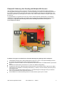
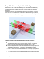
AG4 Series Safety Laser Scanner Application Guide The AG4 Scanner (the Scanner) can provide a protective function only when its settings and connections (software configuration, Protective and Warning Field dimensions, electrical interfacing, mounting, environmental conditions, supplemental safeguarding, etc.) are coordinated with its application. The checklist items below and the following application examples are intended to give additional guidance in applying the Scanner. Direct any questions to Banner Engineering at the numbers on the back page. Application Check List Items The following items are provided to assist in creating a checklist or to be included in a risk assessment for the application of the Scanner. Additional items may be required, depending on the application (see Section 3 of the Scanner User Manual, p/n 144924). NOTE: When Section and Figure numbers are referenced in this document, they refer to sections and figures in the User Manual. Review the Scanner User Manual (in particular, Sections 1.5 and 1.11). Identify the appropriate application (e.g., required resolution, field orientation, etc.): o Area Guarding (Danger zone guarding) o Area Guarding – Leg detection (Leg detection –danger zone guarding) o Vertical Guarding – Hand Detection (Hand protection –point of operation) o Vertical Guarding – Arm Detection (Arm protection –point of operation) o Vertical Guarding – Body Detection (Body protection –danger zone guarding) o Access/Perimeter Guarding (Passage Control –access guarding) o AGV – Automated Guided Vehicle (Mobile vehicle) Determine the area to be safeguarded and the Scanner’s installation location and means. Determine whether the Scanner requires protection from mechanical damage. Ensure that the environmental conditions do not exceed the Scanner specifications. Determine the size and coverage of the Protective Field and Warning Field (if used) depending on: o Physical location of the Scanner installation, o The minimum safety distance (Sections 3.3.4 and 3.3.5), or the stopping distance of the mobile vehicle (Section 3.4.3) o The height (H) of the Protective Field (horizontal applications) o Other factors that may require an increased minimum safety distance (e.g. “shadowing”, adjacent Scanners, retro-reflective surfaces, brake performance degradation) NOTE: It is recommended to visibly mark the Protective/Warning Field boundaries, if possible. Determine whether the Reference Contour Monitoring function is required (at least two sides must be defined as reference contour or surface). Assess the possibility of avoiding detection by the Scanner by climbing/stepping over, crawling under, moving around the protection field(s), either at the perimeter of the fields or in unprotected areas caused by the shadow effect. Determine whether additional/supplement safeguarding is required. Determine the proper startup, start/restart (manual/automatic reset), and other safety-relevant parameters. If the start/restart interlock (manual reset) is used, determine the position for the reset button. Determine whether Field Pair switchover is required and identify the conditions for its use (Section 1.12.4). Determine the method and means of electrical interfacing dependent on the level of risk determined by the risk assessment (e.g., OSHA/ANSI control reliability or ISO 13849-1 category 3 PLd). AG4 Scanner Applications Guide P/N 147900 rev. A 03/2010 1 Contents Example #1: Stationary Area Guarding (Horizontal Danger Zone Guarding) ............................................................. 3 Example #2: Stationary Area Guarding with Field Pair Switchover ............................................................................4 Example #3: Stationary Area Guarding with Multiple AG4 Scanners .........................................................................5 Example #4: Vertical Guarding (Point of Operation – hand detection) with Reference Contour Monitoring ...............6 Example #5: Vertical Guarding (Access Guarding – whole body detection) with Reference Contour Monitoring .......7 Example #6: Mobile Area Guarding on Transfer Carts/Trolleys and Automated Guided Vehicles (AGVs).................8 Example #7: Mobile Area Guarding with Field Pair Switchover ................................................................................ 10 Example #8: Mobile Area Guarding with Side Vertical Guarding .............................................................................. 11 AG4 Scanner Applications Guide P/N 147900 rev. A 03/2010 2 Example #1: Stationary Area Guarding (Horizontal Danger Zone Guarding) Area Guarding uses a horizontal sensing field (i.e., Protective or Warning Fields) to continually sense an individual within a safeguarded area. Area Guarding can reduce or eliminate the possibility of a pass-through hazard (see Section 3.3.6) that could result in an individual being exposed to unexpected machine startup or motion. As an individual approaches, the Warning Field (the green area) can illuminate a warning beacon or sound an alarm that the Protective Field (the red area) is about to be entered. In conjunction with markings on the floor, the use of a Warning Field can eliminate intermittent stopping due to individuals being unaware of the safeguarded area. When the Protective Field is encroached upon, a stop is issued and the hazard is brought to a safe state. Typical considerations for horizontal stationary area guarding: The typical selection for the application in the AG4soft program is “Leg detection –danger zone guarding” (i.e., Area Guarding – Leg detection) with a resolution of 50 mm. In this example the Scanner is mounted in the center of the operator work station to maximize the available size of the Protective and Warning Fields. The Scanner is mounted directly to the cell’s perimeter guarding fencing 300 mm above the floor to prevent crawling under the Protective Fields. In this example, physical damage is not expected because the fencing provides adequate protection. If interference with the operator is expected, the Scanner can be recessed into the fencing to minimize exposure. The typical manufacturing setting is well within the Scanner's environmental ratings. The size and coverage of the Protective Field must ensure that the hazard cannot be accessed by moving (reaching) around, under, or over the Protective Field. Access to the hazard is prevented by the fencing along the side of the Protective Field, which minimizes the required floor space. For this example, assume a robot stopping time of 100 ms, Scanner response time of 80 ms, the response time of a safety interfacing device is 25 ms (UM-FA-9A safety module). Because an individual can reach over the detection plane by bending at the waist, the Dpf adder is equal to 1200 mm (U.S. formula) and the Measurement Tolerance Factor (ZSM) must be accounted for. This gives a safety distance of: Ds = 1600 mm/s x (0.1s + 0.08s + 0.025s) + 1200 mm + 83 mm = 1611 mm (63"). In other words, the leading (outside) edge of the Protective Field must be 1611 mm (63") from the nearest hazard. It is recommended to mark the boundary of the Protective/Warning Field on the floor. The use of the Reference Contour Monitoring function can prevent shifting of the Protective Field and is recommended for stationary applications. This example has no factors that would require an increase in the safety distance. There is no possibility of easily stepping, climbing or otherwise avoiding detection. Because there is no pass-through hazard (see Section 3.3.6), the Scanner can be configured for “automatic start/restart (reset)”. However, the machine control circuitry must be designed so that one or more initiation devices must be engaged (i.e., a conscious act is required) to start the machine. Further, any initiation devices (or reset switches) must comply with Section 3.3.7. For the purpose of this example, the UM-FA-9A Universal Input Safety Module was used and interfaced in a control reliable (category 3 or 4) method as described by Section 3 and Figure 3-19. AG4 Scanner Applications Guide P/N 147900 rev. A 03/2010 3 Example #2: Stationary Area Guarding with Field Pair Switchover An Area Guarding application can use the Field Pair Switchover function to automatically allow access to one area while simultaneously guarding another hazardous area. This can improve machine cycle efficiency by allowing the operator to remove/place parts while the operation is in a different area, for example. The robot position (i.e., the location of the hazard) is monitored to identify when no hazard exists at one work station, at which time the Field Pairs are switched. The Field Pair Switchover function is much like a muting application for a safety light screen. In addition to the typical considerations for horizontal stationary area guarding (listed in example #1), for this example: Ensure that no individual is exposed to a hazard while employing the Field Pair switching function. The risk assessment should determine the applicability of this function, means of selecting Field Pairs in respect to failure modes, and whether supplemental safeguarding is required. Configure the Scanner to power up with the appropriate Field Pair in the “Scanner Start” table (e.g., allow power up with FP #1 only, FP #2 only or either Field Pair). For this example, the “Permitted Field Pair switchover” table should be configured to allow switching from FP #1 to FP #2 and from FP #2 to FP #1. In higher risk applications that require control reliability (category 3 or 4) interfacing, it is highly recommended to use redundant sensors or switches to initiate or enable a Field Pair change. AG4 Scanner Applications Guide P/N 147900 rev. A 03/2010 4 Example #3: Stationary Area Guarding with Multiple AG4 Scanners Area Guarding is frequently used in conjunction with other safeguards, such as interlocked gates on fencing or vertically positioned safety light screens/grids (i.e., perimeter guarding). The purpose of the safeguarding located at the perimeter of the work cell is primarily to detect entry into the hazardous area, while the area guarding (i.e., the Scanner) is responsible for preventing machine restart or other machine hazards while the individual remains within the work cell. In such applications, it is important not to have any voids or unmonitored areas (“dead spaces”) in the detection capability of the Area Guarding system. The Scanner can be configured for irregularly shaped protection fields to accomplish this. Important: Area Guarding and Perimeter Guarding should not be used in place of Lockout/Tagout procedures. In addition to the typical considerations for horizontal stationary area guarding listed in example #1: Install multiple Scanners with a vertical offset height of 100 mm (or more), or use physical shielding to prevent one Scanner from interfering with another Scanner (see Section 3.3.2). Be aware of the effect of needle- and cone-shaped fields and eliminate areas of unreliable detection (see Section 3.3.1). Eliminate the “shadow effect” (see Section 3.3.1) and/or use additional safeguarding. Configure the Scanner for start/restart interlock (manual reset) to ensure that the Scanner does not turn ON its safety outputs if an individual is momentarily undetected (e.g., climbs up onto the machinery above the plane of the Protective Field). Also configure any perimeter guarding systems (e.g., an interlocked gate or safety light screen) for a manual reset; any reset switches must comply with Section 3.3.7. Use the Reference Contour Monitoring function to monitor whether a gate is open or closed. AG4 Scanner Applications Guide P/N 147900 rev. A 03/2010 5 Example #4: Vertical Guarding (Point of Operation – hand detection) with Reference Contour Monitoring In applications in which the Scanner’s Protective Field is positioned vertically to detect a hand, an arm, or an entire body, the Reference Contour Monitoring function must be used. This is to ensure that the Protective Field does not move or otherwise become repositioned, negatively affecting safety distance or otherwise creating voids or gaps or other access to the hazard. Typical considerations for vertical guarding when detection of the hand or arm is required: The typical application selection in the AG4soft program is “Hand protection –point of operation” (i.e., Vertical Guarding – Hand Detection) with a resolution of 30 mm. In this example the Scanner is mounted in the center of the opening, facing down to maximize the available size of the Protective Field and to minimize the accumulation of dust on the Scanner's front screen (window). In this example, physical damage is not expected because the Scanner is mounted above and away from the probable path of the material being placed into and being removed from the guarded area. The typical manufacturing setting is well within the Scanner's environmental ratings. The size and coverage of the Protective Field must ensure that the hazard cannot be accessed by moving (reaching) around, under, or over the Protective Field. Access to the hazard is prevented by the Protective Field overlapping the machine frame and maintaining the proper safety distance. For this example, assume a machine stopping time of 80 ms, Scanner response time of 80 ms, the response time of a safety interfacing device (UM-FA-9A safety module) is 25 ms. Because the resolution is fixed at 30 mm, the Dpf adder is equal to 78 mm (U.S. formula). This gives a safety distance of: Ds = 1600 mm/s x (0.08s + 0.08s + 0.025s) + 78 mm = 374 mm (14.7"). In other words, the plane of the Protective Field must be no closer than 374 mm (14.7") from the nearest hazard. The use of the Reference Contour Monitoring function is required for vertical guarding applications (i.e., the blue shaded areas). In this example, no factors would require an increase in the safety distance. Because there is no pass-through hazard (see Section 3.3.6), the Scanner can be configured for “automatic start/restart (reset)”. However, the machine control circuitry must be designed so that one or more initiation devices must be engaged (i.e., a conscious act is required) to start the machine. Further, any initiation devices (or reset switches) must comply with Section 3.3.7. For the purpose of this example, the UM-FA-9A Universal Input Safety Module was used and interfaced in a control reliable (category 3 or 4) method as described by Section 3 and Figure 3-19. AG4 Scanner Applications Guide P/N 147900 rev. A 03/2010 6 Example #5: Vertical Guarding (Access Guarding – whole body detection) with Reference Contour Monitoring The application below uses two Scanners with Field Pair Switchover to safeguard a pallet load/unload station. The two Protective Fields per Scanner are enabled (the red lines) and disabled (pink shaded areas) as pallets are loaded/unloaded and as they enter/exit the work cell at the rear of the station. The Scanner's FP inputs are used to identify the position of a pallet, to determine which Protective Field to disable. The Reference Contour Monitoring (blue shaded areas) ensures that Protective Fields are in the proper position. In addition to the typical considerations for vertical guarding listed in example #4: In the example shown above, the objective is to prevent an individual from entering an area; thus detecting the body (torso) is required. The typical application selection in the AG4soft program is “Body protection –danger zone guarding” (i.e., Vertical Guarding – Body Detection) with a resolution of 150 mm. In this example, Scanners are mounted in the center of the two entry/exit points to allow switching of the Protective Field, depending on whether access is required to the left or to the right. In this example, physical damage is not expected, since the Scanner is mounted above and away from the probable path of the forklift. If impact is possible, a mechanical guard/shroud can be added to protect the Scanner, without blocking the Protective Fields. The typical manufacturing setting is well within the Scanner's environmental ratings. The size and coverage of the Protective Field must ensure that unrestricted or accidental entry to the work cell is prevented. Two Scanners are used to create four Protective Fields to cover each end of the pallet load/unload station (i.e., left side PF, right side PF, both sides PF, and “no” Protective Field ). When no pallets are at the station, the front Scanner has a Protective Field that covers both sides; the rear Scanner has “no” Protective Field enabled to allow pallets to be fed into the station (i.e., pallets exiting the cell). As pallets are loaded, sensors monitoring the pallet position switch the Field Pairs to “turn off” the front Scanner’s right side and “turn on” the rear Scanner’s Protective Field for that side (as shown). This allows the forklift to pick up the pallet and remove it. When the front Protective Field is inactive, the pallet must completely block the opening to prevent access. When the pallet is removed, that Protective Field must immediately be re-activated. The use of the Reference Contour Monitoring function is required for vertical guarding applications (i.e., the blue shaded areas). For this example, assume a machine stopping time of 200 ms, Scanner response time of 80 ms; safety interfacing device (UM-FA-9A safety module) response time is 25 ms. Because the resolution is fixed at 150 mm, the Dpf adder is equal to 900 mm (U.S. formula). This gives a safety distance of: Ds = 1600 mm/s x (0.2s + 0.08s + 0.025s) + 900 mm = 1388 mm (54.6"). In other words, the plane of the rear Protective Field must be no closer than 1388 mm (54.6") from the nearest hazard (assuming no hazard inside the load station). Configure the Scanner for start/restart interlock (manual reset) to ensure that if an individual interrupts an active Protective Field while attempting to enter the guarded area that the Scanner's OSSD safety outputs remain OFF until manually reset after the individual exits the cell. For the purpose of this example, the UM-FA-9A Universal Input Safety Module was used and interfaced in a control reliable (category 3 or 4) method as described by Section 3 and Figure 3-19. AG4 Scanner Applications Guide P/N 147900 rev. A 03/2010 7 Example #6: Mobile Area Guarding on Transfer Carts/Trolleys and Automated Guided Vehicles (AGVs) On mobile applications, such as transfer carts, the Scanner monitors the area directly ahead of the cart using both the Warning and the Protective Fields. If something is detected within the Warning Field (the green area), the alarm output signals the vehicle logic to slow the vehicle and sound a horn (or other awareness device). The Scanner stops the vehicle when something is detected within the Protective Field (the red area). If the speed increases or decreases, alternate Field Pairs can be used to adjust for varying stopping distances (see example #7). Typical considerations for mobile vehicle guarding (horizontal fields): The typical selection for the application in the AG4soft program is “AGV – Automated guided vehicle” (i.e. Mobile vehicle with a resolution of 70 mm). In this example, the mobile vehicle is a transfer cart that travels in two directions along a pair of rails. Each direction of travel is guarded by separate, individually configured Scanners on either end of the vehicle, mounted 150 mm (5.9") above the plane of the floor (not the rails). The plane of the Protective Field should not exceed 200 mm (7.9") above the floor. In this example, physical damage is not expected because the path of travel is restricted. The typical manufacturing setting is well within the Scanner's environmental ratings. (Continued on next page) AG4 Scanner Applications Guide P/N 147900 rev. A 03/2010 8 Example #6 continued Protective Field Length (Minimum Distance D): For this example, assume a maximum vehicle speed of 1200 mm/s (48"/s), a breaking distance of 900 mm (35"), Scanner response time of 160 ms, the response time of a vehicle drive and safety interfacing 100 ms, which results in an overall stopping distance of 1212 mm (48"). DSD = [1200 mm/s x (0.1s + 0.16s)] + 900 mm. This value is added to the Additional Distance Factors (Z) to determine the Protective Field length, which for this example are: ZSM = 83 mm (3.3") The farthest point of the Protective Field from the Scanner along a radial is less than 3500 mm (138"), which is at far corners. Zrefl = 0 The possibility of retro-reflectors located within the scanning plane of the Protective Field can be excluded. ZF = 100 mm (4") to the The ground clearance of the transfer cart’s sides is 60 mm (2.4”) and the wheels are not accessible. ZA = 500 mm (20") The possibility of crushing/trapping hazard against the overhanging conveyor and the transfer cart is an application specific addition for this example. The total Protective Field length (Minimum Distance) from the Scanner to the leading edge of the Protective Field is 1895 mm (75"). Protective Field Width (Additional Side Distance Z): The Z factors to determine the Protective Field width are primarily the same as above (ZSM = 83 mm, Zrefl = 0, ZF = 100 mm), but the application specific adder, ZA(SIDE), is now used to account for the entire area to the sides the cart and under the overhang of the conveyor. This distance is 300 mm (12"); ZSM + ZF = 183 mm (7.3"), thus ZA must equal 117 mm (4.7") to ensure the entire area to the sides of the cart are monitored. The total width of the Protective Field for this example is 1666 mm (66"), which is the width of cart of 1066 mm (42") plus the value of the two 300 mm side distances. The 190° Protective/Warning Field” option should be used to minimize any unmonitored area at the Scanner 's sides. The vehicle’s maximum speed should be identified in the Scanner’s configuration. In this example the maximum speed is 1200 mm/s, so the “up to 1500 mm/s” option would be chosen. The Warning Field is used to slow the transfer cart and sound a horn if an object is detected. The design of the transfer cart ensures that there are no protruding loads (e.g., pallets) that could become a hazard. The fencing (supplemental safeguarding) along the path of the transfer cart reduces the risk of an individual stepping directly in front of the cart; this allows the Protective Field width to be minimized. The fencing also reduces, but does not eliminate, the possibility of crushing/trapping hazards between the transfer cart and the conveyor because the individual is detected by the leading edge of the Protective Field. In this example, the movement of the transfer cart is controlled primarily by on-board logic that is safety-rated. This allows the movement to begin after the material control system (conveyor logic) commands the cart to a specific location. Automatic start and restart (automatic reset) function must incorporate a two-second delay after the Protective Field becomes clear (per BS/DIN EN 1525). The on-board logic of the transfer cart that controls beginning and stopping motion and the means of electrical interfacing must be evaluated during the risk assessment to meet the required level of safety performance (e.g., control reliability or category 3 or 4). AG4 Scanner Applications Guide P/N 147900 rev. A 03/2010 9 Example #7: Mobile Area Guarding with Field Pair Switchover Similar to the transfer cart on rails in example #6, the Scanner protects people who are located in the path of an Automated Guided Vehicle (AGV). As in example #6, the distance between the Protective Field front edge and the vehicle front must be greater than the stopping distance of the vehicle at its selected speed and at maximum load. As the AGV approaches a turn, the on-board logic slows the speed to prepare for the turn, at which time the Protective Field can be reduced by switching to an alternate Field Pair. AGVs that have a complicated motion path that includes turns to either the left or right can use multiple Field Pairs to “look” around a corner. The control system selects speed-dependent Protective Fields and can activate side Protective Fields when the vehicle is turning. As a corner is approached, the primary Field Pair (the green and red areas) guarding directly in front of the AGV is switched to an alternate Field Pair (the green and red shaded areas) that allow the AGV to make the turn without the larger primary Protective Field detecting a column or wall. In addition to the typical considerations for mobile area guarding listed in example #6: When utilizing Field Pair switchover, the Minimum Distance D and Side Distance Z (Protective Field length and width) must be calculated individually for all Protective Field pairs. A horn, light, or other awareness means should be used to signal the approach and the turning maneuver as supplemental safeguarding to alert an unaware individual of the approaching hazard if the AGV is in a “blind spot” (e.g., around the corner). The Field Pairs allowed at startup (enabled at Scanner powerup) and which Field Pair switchovers are permitted, must be identified in the Scanner’s configuration. Only those combinations that are necessary should be allowed. The on-board logic of the AGV that controls beginning and stopping motion, the means of selecting (switching) the Field Pairs, and the means of electrical interfacing must be evaluated during the risk assessment to meet the required level of safety performance (e.g., control reliability or category 3 or 4). AG4 Scanner Applications Guide P/N 147900 rev. A 03/2010 10 Example #8: Mobile Area Guarding with Side Vertical Guarding Vertically guarding the sides of transfer carts, material-handling trolleys, and Automated Guided Vehicles (AGVs) prevents contact with objects that may have overrun the stop position of a conveyor, which could result in damage to the mobile vehicle and the conveyor. This type of guarding can also be used for situations which have the possibility of a crushing/trapping hazard, e.g., a distance less than 500 mm (20") between the sides of the Scanner and a physical structure. Two Scanners are positioned to create horizontal Protective Fields, to prevent running over objects or individuals in the path of the vehicle. A second pair of vertically mounted Scanners is positioned to detect objects at or above the horizontal plane of the Scanners that are looking ahead of, and behind the vehicle. In this configuration, the "leading edge” of the Protective Field is now provided by the vertical edges on the sides of the Scanner. These edges will detect the torso of an individual; 150 mm resolution is typically selected. In addition to the typical considerations for mobile area guarding listed in example #6: 150 mm resolution is selected for torso detection. Other resolutions (e.g., 70 mm) can be selected, depending on the application. The leading edge of the vertical Protective Field should be no shorter (smaller) than the corresponding horizontal Protective Field (assuming that the response times and safety distances are equal). Position the vertical Protective Fields at a slight angle so that the lower Protective Field edges protrude over the vehicle width by the amount of the additional distances ZSM, ZF, ZREFL and ZA when required (see example #6). The configuration of a reference contour, as with other vertical guarding applications, is not required, because the approach of the individual is detected by the edge of the Protective Field and not the plane. As with the horizontal Protective Fields, the vertical Protective Field must be checked (verified) on a periodic basis. Crushing/trapping hazards can be minimized by supplemental safeguarding, such as by preventing access (e.g., fencing) or causing the individual to be detected by the leading edge of the horizontal Protective Field. AG4 Scanner Applications Guide P/N 147900 rev. A 03/2010 11 AG4 Scanner Applications Guide P/N 147900 rev. A 03/2010 12