1
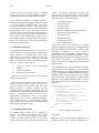
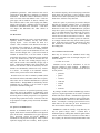
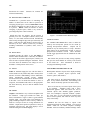
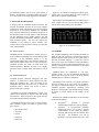
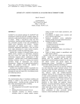
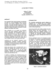
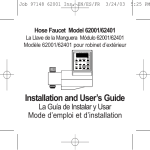
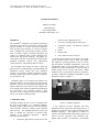
Proceedings of the 1997 Winter Simulation Conference
ed. S. Andradóttir, K. J. Healy, D. H. Withers, and B. L. Nelson
AUTOMOD TUTORIAL
Matthew W. Rohrer
AutoSimulations
655 E. Medical Drive
Bountiful, Utah 84010, U.S.A.
trucks, AGVS, and human movers)
ABSTRACT
TM
The AutoMod simulation system differs significantly
from other systems because of its ability to deal with the
physical elements of a system in physical (graphical)
terms and the logical elements of a system in logical
terms. AutoMod also offers advanced features to allow
users to simulate complex movement (kinematics and
velocity) of equipment such as robots, machine tools,
transfer lines, and special machinery. All graphics are
represented in 3-D space with unlimited viewing control,
including: translation, rotation, scale, light-sourced
solids, perspective, and continuous motion viewing.
•
Conveyors (including belt and roller types)
•
Automated Storage and Retrieval Systems
(AS/RS)
•
Robots
•
Bridge Cranes
•
Power and Free Chain Conveyors
To define material movement systems, the user simply
creates geometric entities, such as paths and stations,
then inputs the operating parameters, such as velocity
and acceleration. AutoMod automatically creates the
corresponding logic for the movement systems. 3-D
animation is created automatically as well, providing a
realistic picture of how a facility will operate. Model
animation can be viewed from any angle or perspective,
providing visualization capabilities unmatched in other
simulation systems (see figure 1).
The AutoMod CAD features are used to define the
physical layout of manufacturing, material handling, and
distribution systems. Unlike most other simulation
software, the powerful AutoMod graphical interface
accurately captures the physical constraints of distance,
size, and space in 3-D.
AutoMod consists of two working environments. The
build environment is for the physical and logical model
definition. After the user has defined the physical and
logical components of the model, it is then compiled into
an executable model, where the simulation and animation
run concurrently. The executable model is fully
interactive, it can be stopped at any instant in simulated
time to view statistics and model status.
1 INTRODUCTION
Figure 1. AutoMod Animation
AutoMod combines the ease of use of a simulator with
the power and flexibility of a simulation language.
Simulators usually address specific real-world problems
with predefined constructs, making model definition
quick and easy. The AutoMod movement systems aid
users in defining the movement of material either
manually or by automated equipment.
Material
movement systems include:
•
A big difference between AutoMod and other
simulation software is that users deal with geometry in a
graphical way and create logic using a fourth-generation
simulation language. This approach is intuitive to
engineers who understand how their facilities operate but
who do not have experience with simulation tools.
Model output includes 3-D animation, automatically
Transporter (path/vehicle systems such as fork
657
658
Rohrer
collected statistics, and business graphs. AutoMod
provides users with a rich environment that facilitates
understanding and analysis of manufacturing systems.
The animation provided in AutoMod models is
concurrent, meaning that the graphic pictures are running
in real time with the simulation model. The model
execution environment is interactive, allowing the user to
stop and start the simulation, run without animation in an
accelerated time scale, and select objects from the
animation screen to gather more information. Statistics
can be viewed at any time during a simulation run.
These model execution features make it easier to verify
and validate models of complex systems and provide a
forum for communication about system performance
among project team members.
2 AUTOMOD INTERFACE
An AutoMod model consists of one or more systems. A
system can either be a process system, in which control
logic is defined, or a movement system. Each model
must contain one process system and may contain any
number of movement systems. Models can be created
without any animation or material handling systems if
necessary. Processes contain logic to:
•
Control the flow of either manufacturing
materials
•
Contend for resources
•
Wait for user-specified times.
Loads can move between processes with or without
using movement systems.
Loads that flow through the process logic have the
ability to claim and release resources, enter and leave
queues, be added to and removed from order lists,
change the value of variables, counters, and load
attributes, create a new load or kill an existing load, read
from and write to external files, and determine the next
process. All interarrival and event times can be
represented by deterministic values or be derived
randomly from one of several statistical distributions.
The AutoMod interface is window-oriented, utilizing
menus, dialog boxes, selection lists, and a mouse-based
editor for developing process logic.
3 AUTOMOD WORLD VIEW
An AutoMod model is made up of a collection of
systems. Any number of movement systems can be
defined. A process system connects the movement
systems to the logical flow of products. In the process
system, loads move between processes (locations) and
compete for resources (equipment, operators, and
queues). The load is the active entity, executing action
statements that are connected to the processes. Typical
action statements give users the ability to:
•
•
•
•
•
•
•
•
•
•
Use machines/operators
Move into queues
Clone new loads
Change load types
Wait on user-defined delay lists (order lists)
Increment/decrement counters
Set variable values
Read from data files
Send to other processes
Make conditional tests
The process system is the backbone of an AutoMod
model, providing the general-purpose simulation features
required to model real-world problems. While material
movement is important, it is not critical in
manufacturing. No value is added to a product while it is
being moved around a manufacturing facility. Valueadded operations are performed by machines, processes,
and workers in the facility. The AutoMod process
system is where the value-added operations and control
logic are defined.
The AutoMod process system includes a simulation
language based on action statements. Action statements
combine the power of a structured language with the ease
of use of English-like, manufacturing-oriented syntax.
AutoMod models are not limited in any way, so model
logic can be of any size and complexity. The power and
flexibility of the AutoMod language makes it easy to
model any situation. Figure 2 is an example of a process
procedure:
begin Pfixit arriving procedure
move into FixQ
if FixedYet = 1 then send to die
else begin
choose a resource from among
Picker(1), Picker(2)
whose current loads is minimum
save choice as RecIdle
use RecIdle for uniform 10, 5 min
set FixedYet to 1
send to SizeWeigh
end
end
Figure 2. Sample Procedure Logic
3.1 LOADS
Loads are the active entities in AutoMod and can be
created in many ways, including deterministic or
AutoMod Tutorial
probabilistic generation. Their interarrival rate can be
read from an ASCII data file or attached to a statistical
distribution. Predefined random distributions can be
used to fit most real-world random events. Loads are
given types, such as “RedCar” or “PartA,” and they can
have attributes such as color, stock keeping unit (SKU),
priority, and cycle time. Attributes can be accessed and
modified in AutoMod action statements. Loads have
3-D shapes and dimensions like other entities in
AutoMod.
3.2 RESOURCES
Resources in AutoMod are used to represent machines,
operators, fixtures, containers, and any other finitecapacity objects. Users can define the states of a
resource. Thus, a machine can be blocked or starved, or
an operator can be offshift or in a meeting. AutoMod
also provides a powerful interface for defining resource
cycles. Resource cycles are the definitions for how and
when a resource changes state. Cycles can be based on
calendar or absolute time, or on the number of units
processed by the resource. Default states can be attached
to the user defined states, and are divided into two
categories. The first is the working category (busy or
idle), and the second is the availability category (up or
down). During the animation, state colors indicate the
status of each resource, and can be defined by the user.
Statistics are automatically collected for every resource
in a model. An example of an automatic resource
statistic is the percent of time in the offshift state.
Resource states can also be defined by MTBF (mean
time between failures) and MTTR (mean time to repair).
These times can use statistical distributions to represent
random failures. Though MTBF is calculated by modelsimulated time by default, it can be based on parts
processed or machine running time.
Loads use resources for specified processing times.
These times can be deterministic or probabilistic, using
built-in statistical distributions to simulate randomness.
Processing times are either part specific or are applied to
all parts using a particular resource. Resources can also
be preempted if a higher priority load needs immediate
attention.
3.3 QUEUES AND ORDER LISTS
Because an AutoMod model is graphical as well as
logical, loads must be located somewhere in the physical
space of the model. AutoMod has two types of physical
space: movement systems and queues. Queues in
AutoMod are both physical and logical. They can have
capacities ranging from one to infinity. When a queue
659
has reached its capacity, the next load trying to enter that
queue must wait until there is space available. Queue
contents can be shown dynamically in the animation, and
loads can be “stacked” in any direction.
Loads at a queue or process may be sorted or delayed
until they are explicitly ordered to leave. To determine
which action should take place next, the loads place
themselves on order lists. An order list is not a physical
entity like a queue, but a logical element that provides a
way to sort loads that have been delayed for any reason.
When one load is on an order list, another load or
vehicle must execute an order action to remove it. Loads
can be ordered to move to another process or order list,
or to simply continue where they left off in their process
logic. Order lists can be sorted by load priority or other
user defined load attributes, either in ascending or
descending order.
3.4 VARIABLES AND COUNTERS
Data may be stored in an AutoMod model using
variables. Variable values are changed using the “set”
action as follows:
set Vtime to 123.456
Variables can be used in calculations or can be
logically compared to other variables. In addition to
integer, real, and string types, variables can also be used
to store pointers:
•
•
•
•
•
•
•
processes
queues
resources
order lists
counters
loads
locations
By setting a variable to another AutoMod type, such as
a process, elegant approaches can be used to construct
flexible and concise models. AutoMod also supports the
notion of arrayed entities, making it easier to model realworld systems that are often two- or three-dimensional in
nature. An example is a sorting system with two levels,
where there are 20 sort lanes per level. References to
each level would be made in arrayed variables.
Counters are similar to variables, except that they can
only be positive integer values. Counters have a
maximum capacity, making them useful for global traffic
control. When a load tries to increment a counter that is
at its capacity, the load will be delayed until another load
660
decrements the counter.
collected automatically.
Rohrer
Statistics for counters are
3.5 TRAFFIC LIMITS AND BLOCKS
AutoMod has a powerful means of controlling the
number of entities that can be either in processes or
occupying physical space. Process traffic limits control
the number of loads that are either on their way to or are
in a process. Blocks control the number of entities
occupying a physical space, which is very useful for
preventing transporter vehicle collisions.
Blocks may have any capacity, but the capacity is
generally set to one. Transporter vehicles (AGVs, fork
trucks, etc.) and loads increment blocks automatically
when moving through the physical space defined by the
block. Loads can also claim blocks in process logic, as
directed by the user. Blocks can have any 3-D shape,
including combinations of cylinders, cubes, cones, or
frustrums.
3.6 TEXT LABELS
AutoMod provides the ability to use text labels to
enhance model communication. Labels may be added to
any location in the model’s physical space, and they can
either be static or dynamic during the simulation. Labels
can rotate when the animation view changes or can be
attached to a fixed position on the screen.
Figure 3. AutoMod Timeline Business Graph
3.9 RUN CONTROL
The AutoMod run control allows users to define the
warm-up and steady-state periods for the model by
resetting time-persistent statistics. Reports can be
printed for any run control period, or “snap.” Business
graph output can be automatically created, as well as
post-processed animation records. These animation
records can be played back after the simulation run with
AutoViewTM.
Run control also provides an entity tracing capability
that gives the model builder an event-by-event account
of the model run. Trace information is useful in
verifying and validating a model.
3.7 TABLES
4 PICTURE CONSTRUCTION IN 3-D
Tables in AutoMod supply the user with the means to
collect statistics on any model entity and to classify those
statistics for better understanding of their distribution.
Tables automatically provide average, standard
deviation, maximum, and minimum for all values entered
in the table. Users can define the number of “bins” or
categories, and AutoMod adds values to the appropriate
bin when directed by the user with the tabulate action
statement.
Both dynamic and static objects can be displayed during
a model run.
Dynamic objects represent loads,
resources, queues, and statistics.
3.8 GRAPHS
Graphs in AutoMod are easy to define and update with
the animation. Graph types include bar charts, pie
charts, and timelines. Figure 3 shows a typical timeline
business graph. Any model entity can be attached to a
graph, including transporter vehicle velocity, number of
loads on a conveyor section, or average utilization of a
machine. Graphs can be printed or plotted to a variety of
supported output devices, and graph displays can be
controlled using the AutoMod language.
The static layout is the background graphics of the
plant. It may contain column lines, aisle markings, and
walls. Labels can identify specific areas in the facility.
There are several ways to create a layout of the system
to be modeled.
AutoMod comes with a threedimensional graphics editor that allows the user to
construct objects from standard graphic primitives.
Cone, box, hemisphere, trapezoid, frustrum, cylinder,
arc, vector (list), set, text, and triad are primitives that
can be selected, placed, and scaled to create any static
entity in the facility.
AutoMod also has the ability to import CAD
information through the IGES standard. The acronym
“IGES” stands for the Initial Graphics Exchange
Standard. IGES is an industry standard exchange format
AutoMod Tutorial
for translating graphic data from one CAD system to
another. Any IGES file of a plant layout that was created
in a CAD system can be easily imported into AutoMod.
5 RUN-TIME ENVIRONMENT
In keeping with the AutoMod interactive features, the
run-time environment provides the user with complete
control of the model. The model can be viewed with the
animation on, or run with the animation off. AutoMod
uses concurrent animation; the simulation progresses as
the animation picture is being updated. With animation
off, the simulation doesn’t update graphics, but still
performs all statistical calculations while the simulation
clock proceeds rapidly. The user can suspend the
simulation at any instant to review statistics, take
resources down, set break points or alarms, or control the
view of the animation.
661
Figure 4 is an example of a transporter vehicle report.
Vehicle states are tracked during the entire model run
and reports are generated automatically.
Reports can be sorted alphabetically or numerically for
easier analysis. The user can also develop and generate
custom reports from within process procedures.
Figure 4. AGVS Statistics Report
5.1 VIEW CONTROL
6 SUMMARY
AutoMod provides a comprehensive, flexible, and easyto-use method of interacting with a model during model
execution.
If the simulation project is in the
experimentation phase where only parameter changes are
made and the model needs to be re-run several times,
AutoMod provides the ability to batch mode runs
without animation. Whether the need is for a highly
interactive mode or a batch mode, AutoMod lets you do
it.
The AutoMod simulation system provides the ability to
define the physical elements of a system using CAD-like
graphics and the logical portion of the system using a
powerful procedural language. A typical user can be
three to ten times more productive using AutoMod in
comparison to using any other simulation language. The
accuracy and degree of detail with respect to movement
systems is unequaled.
5.2 USER INTERACTION
AutoMod provides advanced debugging and trace
facilities. A model can be single-stepped at any time
during the simulation run. Also, the ability to set
breakpoints and alarms allows the user to suspend the
simulation when a certain event occurs or when a
specific clock time is reached.
AutoMod also provides comprehensive reports. The
reports can be displayed on request at any time during
the animation. Printed versions of the reports can also
be specified during model development.
AutoMod automatically keeps track of many statistics.
These automatic reports are linked to specific entity
types, such as
•
•
•
•
•
Movement systems
Processes
Queues
Resources
Order lists
AutoMod allows the construction of very large,
complex models. In fact, the AutoMod language has
proven that the larger the project, the more benefits
AutoMod has over alternative approaches.
AutoMod provides real-time, 3-D graphic animation.
There are no limits to the views or the size of graphics.
The degree of animation realism is also unmatched, as
AutoMod provides light-sourced vanishing point
perspective solid graphics with Z-depth sorting, showing
all entities in correct relation to one another on the
screen.
Enhancing the AutoMod capabilities are the following
extensions and utilities:
•
AutoSchedTM - Provides a powerful
manufacturing template for capacity planning.
•
AutoView - A post-processed animation
package that allows you to create a directed
“walk-through” of the model by panning,
zooming, and moving back and forth in time
and space. The animation view can be
attached to a moving model entity like a load
662
Rohrer
or vehicle, providing a realistic view from the
“inside” of a model.
•
AutoStatTM - Provides enhanced analysis of the
statistics generated by AutoMod by calculating
minimums, maximums, confidence intervals,
Design of Experiments (DOE), and warm-up
period to determine model steady state.
REFERENCES
AutoSimulations, Inc. 1996, AutoMod User’s Manual.
AutoSimulations, Inc. 1996, AutoMod Lessons Guide.
AUTHOR BIOGRAPHY
MATT ROHRER, Vice President of Products, joined
AutoSimulations, Inc. in 1988. Serving as a Simulation
Analyst for five years, Mr. Rohrer completed simulation
projects in distribution, manufacturing, and material
handling. As a user and developer of AutoMod, he has
contributed to the enhancement of the product to make
AutoMod the most powerful simulation product
available. His main interest is in extending the use of
simulation technology beyond its traditional application
in planning and design. Mr. Rohrer received a B.S. in
Engineering from the University of Utah in 1983.