1
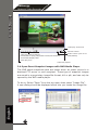
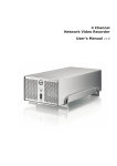
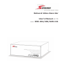
Network Video Recorder
User’s Manual v1.7.5
Model:
SVR-104/108/SVR-116
SEEnergy
English
User’s Manual
Network Video Recorder
Table of Contents
Product Description
6
Install Hard Disk
7
Hardware Illustration
10
I/O Ports and RS-485
12
LEDs Definition
13
Connect to the NVR
15
1. Live View
19
1.1 Retrieve camera’s video stream
21
1.2 Retrieve camera’s status
21
1.3 Perform Sequence Viewing
22
1.4 PTZ Control
23
1.5 Perform PTZ Preset Viewing
24
1.6 Live Video Control Buttons
26
1.7 Change Web UI Display Language
29
1.8 Live View Through iPhone
30
1.9 Live View through Blackberry Phones
33
2. Playback
36
2.1 Methods to Search Playback Videos
37
2.2 Export Playback Videos to AVI Files
43
2.3 Play Exported AVI Videos With NVR Media Player
45
2.4 Open Event Snapshot Images with NVR Media Player
46
3. System Setup
47
3.1 System Configurations
47
3.1.1 Network Settings
47
3.1.2 DDNS Service
49
3.1.3 Time and Date
55
3.1.4 User Account
56
3.1.5 Group Privilege
57
3.1.6 Disk Setup
59
3.2 Channel Configurations 60
3.2.1 Add a Camera
60
3.2.2 OSD Settings
63
3.2.3 PTZ Preset Settings
64
3.2.4 PTZ Preset Sequence
66
3.2.5 E-Map Setting
67
3.2.5.1 Local Map Setting
67
3.2.5.2 Google Map Setting
69
3.3 Event Configurations
71
3.3.1 General Settings
71
3.3.2 I/O Settings
72
3.3.3 Event Servers
74
3.3.4 Event Triggers
77
3.4 Recording Configurations
79
3.4.1 General Settings
79
3.4.2 Schedule Recording
82
2
SEEnergy
3.5 System Options
84
3.5.1 Device Information
84
3.5.2 Logs and Reports
85
3.5.3 Maintenance
85
Reboot the NVR
86
Reboot NVR At a Specific Time Automatically 87
Firmware Upgrade
88
Reset the NVR to Factory Default
90
3.5.4 DO Status
91
3.5.5 Disk Status
91
3.5.6 USB Backup
92
3.5.7 UPS Configuration 98
English
User’s Manual
Network Video Recorder
3
SEEnergy
User’s Manual
Network Video Recorder
Copyrights & Trademarks
Copyright
SEEnergy Corp © 2011
Trademarks
SEEnergy SVR-104/108/116 Network Video Recorder (NVR) is a registered trademark of SEEnergy Corp.
Microsoft and Windows are registered trademarks of Microsoft Corporation.
All other trademarks mentioned in this document are trademarks of
their respective owners.
Disclaimer
This document is intended for general information purposes only, and
due care has been taken in its preparation.
Any risk arising from the use of this information rests with the recipient, and nothing herein should be construed as constituting any kind
of warranty.
SEEnergy reserves the right to make adjustments without prior notification.
English
All names of people and organizations used in this documentís examples are fictitious. Any resemblance to any actual organization or
person, living or dead, is purely coincidental and unintended.
4
SEEnergy
User’s Manual
Network Video Recorder
System Requirements
The following are minimum system requirements for the system to operate Embedded Network Video Recorder (ENVR):
Operating System
Microsoft® Windows® 2000 Professional, Windows® XP Professional
SP2, Windows Vista, Windows 7, Windows® 2003 Server, or Windows®
2008 Server
Browser
Microsoft Internet Explorer 7 or above
CPU
Minimum Intel® Pentium® 4 2.4 GHz or higher (Dual Core is recommended)
RAM
Minimum 1 GB of RAM, 2GB or above is recommended
Network
Minimum 10/100 Ethernet (Gigabit Ethernet is recommended)
Graphics Adapter
AGP or PCI-Express, minimum 1024×768, 16 bit colors.
(We highly recommend to work above the 1024 x 768 resolution to get
the full experience of the software)
• Make sure your display DPI setting is set to default at 96DPI
• To set DPI value, right-click on desktop, choose “Settings” tab >> “Ad-
English
Contents Inside the Installation CD
•
•
•
•
•
•
•
Adobe Acrobat Reader
Smart Device Search Utility
Pi-Vu Central Basic CMS software
NVR Media Player
User’s Manual
Quick installation Guide
Datasheet
5
SEEnergy
User’s Manual
Network Video Recorder
Product Description
The Embedded Network Video Recorder is designed for use within a
surveillance system, and performs recordings and playbacks pictures
from network cameras in the system. It is a recording device using a
hard disk drive to record camera pictures instead of using video tapes
so that pictures recorded by repeated overwriting will not experience
deterioration of the recorded picture quality. Up to 4 (for SVR-104) or 8
(for SVR-108) or 16 (for SVR-116) cameras can be connected via a network and it is possible to record their camera pictures. It is possible to
perform the settings or operate the NVR using a web browser installed
on a PC connected to a network, or remote controller. Recorded video
can be played back from remote site by a PC. Up to 4 PCs (web browsers) can access this unit concurrently and it is possible to perform the
settings and operate this unit. The NVR is compatible with most major
brand cameras and its ability to automatically search and fnd the
available cameras on the network can greatly reduce the user effort
when expanding the system.
• Advance PTZ Control
• Various Types Event Alerts
• Pure Web Based Administration
• Linux-embedded Operating System
• Export Recorded Videos to AVI
• Compatible with Major Brand Cameras
• High Quality Live/Playback Videos
English
• Smart Camera Search
6
SEEnergy
User’s Manual
Network Video Recorder
Install Hard Disk
Start by removing the screws on the side:
Push the top housing forward.
Then lift it up.
English
• The NVR supports SATA I or
SATA II hard disks.
• The NVR supports max. 1.5TB
per hard disk and it supports
total of 2 hard disks (3TB).
7
SEEnergy
User’s Manual
Network Video Recorder
There is a cable connected between the fron LED board and the main
board.
You can remove it from the main board or simply put the top housing on
the side like shown below.
English
Next, slide the hard drive into the tray.
8
SEEnergy
User’s Manual
Network Video Recorder
Make sure the SATA connectors are correctly aligned with each other.
Secure the hard drive with the tool-less screw provided in the box.
English
Place the top housing back and secure it with the bottom housing.
9
SEEnergy
User’s Manual
Network Video Recorder
Hardware Illustration (Front)
16 Channel
English
8 Channel
10
SEEnergy
4 Channel
English
User’s Manual
Network Video Recorder
11
SEEnergy
I/O Ports and RS-485 (Rear)
English
User’s Manual
Network Video Recorder
12
Pin
Signal
1
12V DC
2
GND
3~10
Alarm input
11
Out1
12
Out2
13
Out3
14
Out4
15
RS485+
16
RS485-
SEEnergy
User’s Manual
Network Video Recorder
LEDs Definition
4 Channel
8 Channel
English
16 Channel
13
SEEnergy
User’s Manual
Network Video Recorder
LEDs Definition
HDD x 2
Green
Solid green when the hard disk is mounted
and being accessed.
Red
Solid red for disk fail.
Amber
Network
Status
Power
Alarm
Amber
Green
Amber
Blinking during firmware upgrade.
Green
Shows solid green for normal operation.
Blinking green when firmware upgrade is
done.
Red
Flashes red for failed firmware upgrade.
Green
Normal operation.
Red
System off (power adapter remains plugged
in).
Amber
Blinking amber indicating device is initializing.
Red
Blinking when an alarm occurs.
None
When alarm is reset.
Green
Camera
LED
Amber
Amber
English
Red
14
Solid amber when recording is in process.
Blinking when recycling.
Solid amber for activity on a 1G bps network.
Solid green for activity on a 10/100 Mbps
network.
Solid green, live connected with no event or
recording activity.
Blinking amber, manual or event recording is
being performed.
Solid amber, schedule or continuous recording
is being performed.
Recording is set but no video from camera.
SEEnergy
User’s Manual
Network Video Recorder
Connect to the NVR
There are various ways you can connect to the NVR and below are
the suggested methods for different network setup:
• The NVR is placed in a network with a DHCP server: Connect to
the NVR by using “SEEnergy Device Search” Utility
• The NVR is placed in a network without DHCP server (or you are
connecting to it directly): Access NVR with its default IP
Use SEEnergy Device Search Utility
When the NVR is on a corporate network, or a local area network
where a DHCP server is already present. Run the “SEEnergy Device
Search” utility from a computer which is also on the same network
and locate the NVR via its IP address assigned by the top-level DHCP
server.
English
To begin, launch the “SEEnergy Device Search” utility from the CD
and proceed with the installation:
15
SEEnergy
User’s Manual
Network Video Recorder
Once the installation is complete, check the “Launch the Search AP”
option and click “Finish”:
The search should start automatically and its status should be displayed:
The NVR should be located and its IP address should be displayed:
Double-click on it and the program should automatically access the
NVR’s web administration page from your default browser
English
You may change NVR’s IP address by click on the button highlighted
below.
16
SEEnergy
User’s Manual
Network Video Recorder
You will be prompted for the NVR’s login information before proceeding
to change device’s IP address.
You may click on the button highlighted below to perform search again.
Or double-click on any of the search results to access NVR’s web administration page
perform search again
access NVR’s web administration page
English
You should be prompted for the NVR’s username and password. Enter its default username “admin” and password “admin” and then
click”OK” to enter the system
17
SEEnergy
User’s Manual
Network Video Recorder
Access NVR with its default IP address
The NVR comes with a pre-configured static IP “192.168.101.50”.
However, it is only used when there is no DHCP server presented in
the network. The NVR will turn on its DHCP server function and act
as the DHCP server in the network. To connect to the NVR, use a PC
that is on the same network over a switch or hub, or connect the PC
directly to the NVR using a crossover CAT5 Ethernet cable.
The PC that is connected directly to the NVR (or within the same local
area network) should receive an IP from it. Simply access the NVR
from your web browser with its IP address
English
Again, you should be prompted for the username and password. Enter its default username “admin” and password “admin” and then
click”OK” to enter the system
18
SEEnergy
User’s Manual
Network Video Recorder
1. Live View
SVR-116
Camera List
PTZ Control
Live Video
Live Video Control Buttons
English
SVR-108
19
The 8 channel NVR comes with a 8-video split window
view with one video displays on a larger window. Select a channel from the drop-down menu to display its
video on the larger split window. You can also doubleclick on any of the smaller one to display its video to
the larger window.
SEEnergy
Network Video Recorder
User’s Manual
SVR-104
The “Live View” page provides the following functions:
•
•
•
•
•
•
•
•
•
•
•
Retrieve camera’s video stream
Retrieve camera’s status
Perform Live Sequence Viewing
PTZ Control
Perform PTZ Preset Sequence viewing
Perform manual recording
Take snapshot
Receive audio of a video stream
Send audio
Control “Buzzer”
Change web UI display language
If you are using Windows Vista or Windows 7, please make
sure you open Internet Explorer with the “Administrator”
privilege or log in to Windows with “Administrator” account.
English
Right-click Internet Explorer
20
SEEnergy
User’s Manual
Network Video Recorder
1.1 Retrieve camera’s video stream
The camera list is expanded and displayed on the Live View page.
• Click “All” to display videos in the
8-video mode (SVR-108) or 16video mode (SVR-116)
• Click on a “Group” (ex. Group 1)
to display videos from cameras
under that group in quad view
• Click on any camera to display
video in single-view mode
1.2 Retrieve camera’s status
The camera list can show each camera’s current status. Each status is represented with different colors and their meanings are explained on the left
Camera is connected
Camera is NOT connected
This channel has event triggered and is recording event
Camera is current performing recording
English
This channel has NOT been configured with any camera
21
SEEnergy
User’s Manual
Network Video Recorder
1.3 Perform Sequence Viewing
Sequence view is a function that allows you to view multiple video streams from certain cameras in sequence automatically without
having to select them one by one.
To perform sequence view, select “SEQ View” from the upper-left
hand corner
Next, select one or more camera(s) or camera group(s) for sequence
viewing
Then select dwell interval from the drop-down menu
Finally click “Start” to start sequence viewing
* Click “All Channels” to quickly select all available channels and start sequence
view in single-view mode.
Click “All Groups” to quick select all available groups and start sequence view in
quad-view mode
Or simply select the desired channels and press “Start” to start sequence view
English
The “All Group” button is not available in 4Ch NVR as it only has one group
22
SEEnergy
User’s Manual
Network Video Recorder
1.4 PTZ Control
PTZ control provides functions to pan, tilt, zoom a PTZ camera
as well as the ability to adjust camera focus and iris
Camera(s) that are currently being selected for live viewing will
be listed in the PTZ drop-down menu. Simply select a camera
then use the PTZ control panel to control the camera
English
The bar shown below allows you to control the pan/tilt speed
23
SEEnergy
User’s Manual
Network Video Recorder
1.5 Perform PTZ Preset Viewing
There are three functions provided in the “Preset” section:
• Perform preset point viewing of a particular camera
• Auto pan a particular camera
• Perform preset point sequence viewing
Preset Point Viewing
Start by selecting a PTZ camera from the drop-down list:
Its available PTZ preset points will be listed in the dropdown list shown below:
English
Select a preset position from the drop-down list and click
“Go to” to move the live view to that position
24
SEEnergy
User’s Manual
Network Video Recorder
Auto Pan Viewing
Start by selecting a PTZ camera from the drop-down list:
Use the Auto Pan control buttons to pan right, left and
stop auto pan
Autopan
Pan Left
Stop pan
* Certain cameras do not support bidirectional pan movements. Use the
“Autopan” button for such cameras
Pan right
Preset Point Sequence Viewing
This function allows you to view multiple preset points
from a video of a camera without having to select them
one by one. Once you have defined the prefered preset
points in “Channel Configurations” >> “PTZ Setting”
>> “PTZ Sequence” under the “Setup” menu, click
“Start” in the lower-left hand corner in Live View under
“Preset” and the recorder will begin to display videos from
those preset points in sequence automatically until you
click “Stop”
English
“In the Setup page”
25
In the Live View
SEEnergy
User’s Manual
Network Video Recorder
1.6 Live Video Control Buttons
Each live video window comes with control buttons with functions described below:
Take a snapshot of a live video
Turn on/off audio of a live video
Start/stop recording of a live video (manual recording)
Audio post function
Full screen view of a live video
Keep aspect ratio and true size
English
Keep aspect ratio
26
SEEnergy
User’s Manual
Network Video Recorder
Take a snapshot of a live video
To take a snapshot of a live video, click the
button and
the snapshot of the video will be displayed in a pop up window
shown like below
* If you are running Windows Vista or 7,
please make sure IE is run with the “Administrator” privilege in order for this
function to work properly.
Right-click anywhere on the image and select “Save Image as”
from the pull-down menu
English
In the pop up dialog, name the image file and choose which directory the image will be saved to and click “Save”
27
SEEnergy
User’s Manual
Network Video Recorder
Full Screen View of a Live Video
To view a video in full screen, click the
button. To exit full
screen video, double-click anywhere on the video.
Turn On/Off Audio of a Live Video
You can retrieve audio from a particular camera. Simply click
the
button to do so.
The button will show in different color once the audio is turned
on.
Click on it again to turn off audio.
Start/Stop Recording of a Live Video
You can manually start or stop recording of a live video by using
the
button.
The button will show in different color once the recording is
started manually.
Click on it again to stop recording.
Audio post
English
This function allows user to speak from a PC through a microphone and the audio can be played at the camera side if it has
a speaker connected to it.
28
SEEnergy
1.7 Change Web UI Display Language
You can change the web UI display language from the current
login username link located at the upper-right hand corner. Click
on the link opens up a new window which displays detail information about the user as well as a drop-down menu which lets
you change the displyay language.
English
User’s Manual
Network Video Recorder
29
SEEnergy
User’s Manual
Network Video Recorder
1.8 Live View through iPhone
You can use iPhone and perform single channel live view to the
NVR by using its Safari browser. To be able to view the live video
through the Safari browser, make sure “javascript” is on under
“Settings” >> “Safari” >> “Javascript”
Once Javascript is enabled, click the “Home” button on the iPhone
to go back to the home screen and open the Safari browser
English
Type in the IP address of the NVR in the address bar
30
SEEnergy
User’s Manual
Network Video Recorder
You should be prompted to enter the username and password
to access the NVR
Upon successful login, you should see the live view video of the
first channel
English
Click on the “Channe” drop-down menu to select other cameras
31
SEEnergy
User’s Manual
Network Video Recorder
If a PTZ camera is selected, the corresponding control buttons
will display (control PT only)
English
* Please note that this function is camera dependent and is not available to
all cameras. Certain cameras do not allow adjusting image size and the selection “Auto” will be used.
32
SEEnergy
User’s Manual
Network Video Recorder
1.9 Live View through Blackberry Phones
You can use Blackberry and perform single channel live view to
the NVR by using its Safari browser. To be able to view the live
video through its browser, make sure “javascript” is enabled
under “Browser” >> “Menu button” >> “Options” >> “Browser
Configuration”
2.
1.
Enable the “Support Javascript” option and click the menu button
and click “Save Options”
2.
1.
English
Go to “General Properties
33
SEEnergy
User’s Manual
Network Video Recorder
Make sure two options illustrated below are enabled
Press the menu button and click the “Save Options” to save settings
2.
1.
English
Press the button highlighted below to go back to the browser
34
SEEnergy
User’s Manual
Network Video Recorder
Type in the IP address of the NVR in the address bar
English
You should be prompted to enter its username and password for access
35
SEEnergy
User’s Manual
Network Video Recorder
2. Playback
Methods to search playback
Channels to be played back
Playback video control buttons
Playback video
Playback is a function that allows you to play one or more videos that
were previously recorded by a chosen recording method or due to
an event trigger. The NVR offers synchronized playback from up to 4
channels and various types of search methods are provided to help
you find the footage you need quickly.
You can turn on or off the audio of a recorded video at your choice if
audio was also recorded during the recording of the video.
English
Playback video can be viewed in full screen and snapshots can be
taken and saved during a video playback.
36
SEEnergy
User’s Manual
Network Video Recorder
2.1 Methods to Search Playback Videos
The NVR offers three methods to quickly help users find videos that
were previously recorded:
• Search by time: Specifiy a time range and search videos recorded
within that range
• Search by event: Find videos that were recorded due to event
triggers
• Play by start time: Enter a specific time a video was recorded to
start playing back the video
Search by time chart
• Start by selecting which channel(s) you would like to perform a
search on:
* Selected channels will be marked in red
English
• Select “Search by time chart” from the “Search Method” dropdown list and click “Go” to start the search:
37
SEEnergy
User’s Manual
Network Video Recorder
• Results will then be displayed in a “Date/Channel” table and
boxes marked in blue represent videos found in those dates:
• Click on any blue cell box should direct you to the hour/channel
table if there were multiple videos recorded during that date:
English
* Videos from other cameras that are recorded on
the same date will also be displayed
38
SEEnergy
User’s Manual
Network Video Recorder
• Click on the cell box again will start playing back the videos if
you have reached the end of search results:
English
• Videos found from other cameras that were recorded at the
same time will also be played.
39
SEEnergy
User’s Manual
Network Video Recorder
Search by event
• Start by selecting which channel(s) you would like to perform a
search on:
* Selected channels will be marked in red
• Select “Search by event” from the “Search Method” drop-down list
and click “Go” to start the search:
• Results will then be listed like what is shown below (displays the
oldest record top down). Click on a particular result to start the
playback:
English
* You can cilck “Next Search” to display the next
15 results.
40
SEEnergy
User’s Manual
Network Video Recorder
• You may also specify a new start time to search and display results from then on. You can restrict the number of results to be
displayed at once (max. 30) and perform the search again
Play by specific time
If you know when a recording was taken place, you may choose the
“Play by start time” from the “Search Method” drop-down list
English
Then you will be prompted to enter a specific time and date for the
recorded video.
Use the
41
button to select month, date, and year
SEEnergy
Search by event (Most Recent)
This function quickly displays the most recent event recordings from
the selected channels, displaying the most recent result top down.
You may click “Update” to update the list to display the most recent
result
English
User’s Manual
Network Video Recorder
42
SEEnergy
User’s Manual
Network Video Recorder
2.2 Export Playback Videos to AVI Files
User can export the recorded playback videos stored on SVR-116 to
a local computer and save them in AVI file format. The files can then
be played on the PC by a 3rd party media player such as VLC player
or Windows Media player.
Once you locate the recorded videos with steps described in the previous section, hit the “Export AVI” button on a video window of the
video you wish to export.
* If you are running Windows Vista or 7,
please make sure IE is run with the “Administrator” privilege in order for this
function to work properly.
A new dialog will pop up and allows you to speficy the time frame (or
length) of the video you wish to export
English
Click the
button to pull down the calendar to help you specify
the month, date and the year
43
SEEnergy
User’s Manual
Network Video Recorder
Specify the starting and ending hours of the video by entering numbers in the text boxes
Hit the “Start” button to start exporting. The file will be automatically
named and saved under the C:\ partition
You will be notified once the process is completed successfully
The exported AVI file will be saved under the C partition
English
* ffdshow is required in order to
play the exported AVI file with Windows Media Player. You can get it at
“http://sourceforge.net/projects/ffdshow-tryout/” to download the “ffdshow_beta6_rev2527_20081219.
exe”.
44
SEEnergy
User’s Manual
Network Video Recorder
2.3 Play Exported Playback Videos with NVR Media Player
You can also use the NVR Media Player to play the exported AVI files.
This can save you the trouble of installing third-party media player or
codecs when playing the exported AVI videos.
The NVR Media Player will be automatically installed after the CMS
software is installed. You can launch the player under “Start” >> “All
Programs” >> “IVS” >> “IVS Central Basic” >> “NVR Media Player”
Click “Open” >> “AVI File”
Locate the exported AVI file, and click “open”. (normally under
“C:\ExportFolder)”
English
The video will then start playing
45
SEEnergy
User’s Manual
Network Video Recorder
video play control bar
Volume Control
video play control buttons:
Rewind/Pause (Play)/Stop/Next Frame/Fast Forward/
Screenshot/Display OSD
video play time
Audio Control (click to enable/disable)
Video Play Speed
2.4 Open Event Snapshot images with NVR Media Player
The NVR sends snapshots that are taken when an event occurs to a
destined FTP server or mail recepient. These type of snapshot images
are saved in a proprietary image file format, h4i or p4i, and can only be
opened by the NVR media player.
English
To do so, Select “Open” from the top menu then select “Image File”.
A new dialog should be displayed which lets you locate the image file.
46
SEEnergy
User’s Manual
Network Video Recorder
3. System Setup
3.1 System Configurations
The “System Configurations” page provides users options to setup the
device quickly and properly. After properly configuring all settings in
all the sub-pages, users should expect a fully working network video
recorder that is ready to manage cameras on the network. We will
start by configuring its network settings to make sure it works correctly in your network. Next, we will help you adjust the system time
so videos will be recorder with correct timestamp. To better secure
the system for unwanted disturbance, we will guide you on setting up
user’s account and privileges to prevent settings gets altered by users other than the system administrator. Lastly, we will tell you what
you should expect after installing a hard disk and how to prepare the
hard disk for the video recording.
English
3.1.1 Network Settings
You need to adjust settings in this page for the device to work properly in your network. It is critical that settings here are configured
correctly based on your network configurations so that the recorder
can be administered through the local area network and cameras can
be connected from it.
47
SEEnergy
User’s Manual
Network Video Recorder
By default, the recorder is set to obtain IP address from DHCP server,
it should be sufficient in most network environments, and most likely
you should not need to alter anything in this page. To locate the
recorder, simply use the SEEnergy IP Utility with steps described in
page 12.
If you wish to set the recorder to use a static IP address in your local
area network,
1. Choose “Static IP” from the “Connection Type” drop-down menu
2. Enter the IP address, subnet mask, default gateway address and
DNS server address for the recorder
3. Enable “DHCP Server” under “DHCP Server” if you wish to use the
recorder as a DHCP server, or leave it disabled if there is already a
DHCP server in the network
4. Click Apply for the settings to take effect
The recorder can detect
the presence of a DHCP
server upon startup. It
sets itself to use static
IP address if there is no
DHCP server currently
presented in the network.
Its DHCP server function is also turned on at
the same time to assign
IP addresses to cameras
that are later connected
to the network
o You can manually turn
off the DHCP server function if you wish to use a
separate DHCP server
English
Change the recorder’s IP address would require the recorder to restart.
Restart the device under “system Options” >> “Maintenance” for the
settings to take effect.
48
SEEnergy
User’s Manual
Network Video Recorder
3.1.2 DDNS Service
DDNS, which stands for “Dynamic DNS”, is a method, protocol, or
network service that provides the capability for a networked device,
such as a router or computer system (in this case, the NVR) using the
Internet Protocol Suite, to notify a domain name server to change, in
real time, the active DNS configuration of its configured hostnames,
addresses or other information stored in DNS.
A popular application of dynamic DNS is to provide a residential user’s
Internet gateway that has a variable, often changing, IP address with
a well known hostname resolvable through standard DNS queries.
This is useful if the NVR is placed on the Internet with a dynamic
public IP, which once the DDNS is properly setup, users can access
the NVR remotely with the DDNS domain name without worrying if
the IP hs changed or not.
Please make sure a valid DNS server has been configured under the
“Network Setting” page in order for this function to work properly.
The NVR currently only works with free DDNS service provided by
“DynDNS”. For more information, please go to www.dyndns.com
English
If the NVR is placed behind a router or Internet gateway, please make
sure port forwarding for port 80 is configured on the router or the gatway in order for the DDNS function to properly register with the service.
It’s often suggested to use the DDNS function in the router/
gateway for such case instead.
Once you have the DDNS function successfully up and running, please
DO NOT forget to configure port forwarding for the NVR web port (default 80) and the streaming port (default 9877) in the router/gateway
for remote viewing. You can then type in http://yourddnsdomain in the
browser to access the NVR remotely for live view.
49
SEEnergy
User’s Manual
Network Video Recorder
In order to properly configure the DDNS service function, please register a free DDNS domain name and account from DynDNS first. Go to
www.dyndns.com from the browser to do so.
Click on the “Signup FREE” button to begin
English
Choose the FREE service on the left
50
SEEnergy
User’s Manual
Network Video Recorder
Fill in the necessary fields as illustrated below:
Enter a desired hostname here
Select a desired sub-domain
from the drop-down menu
Click here to automatically fill in
the current public IP in the “IP
Address field”
Pick one or more options here
(any is fine)
Click to go to the next step
English
The page will check whether the hostname you entered has been used
by another user or not as soon as you click the “Add to Cart” button. If
you see below message, simply enter a different and click “Add to Cart”
again
51
SEEnergy
User’s Manual
Network Video Recorder
Once you get to the next page, fill in the necessary fields as illustrated
below
Create an username and a password here. This will be
used in the NVR’s configuration. Enter a valid email address as well.
Enter the security code
Check to agree the license
English
Click to finish creating the
account
52
SEEnergy
User’s Manual
Network Video Recorder
Go back to the NVR’s DDNS service configuration page under “Setup”
>> “System Configuration” >> “DDNS Service”.
Fill in the domain name you picked during the registration in the “Domain Name” field and the username/password you created in the “User
ID” and “Password” field and click “Apply” to finish
English
You can click the “Check DDNS Status” button to check the DynDNS
service status. If you are getting a “Disconnected” message, it means
that DDNS service server is down or the NVR is not connected to the
Internet. If everything is ok normally, you should be prompted with a
success message
53
SEEnergy
Notice the “Connection Status” displays the status of whether the NVR
has been able to successfully update its current public IP address to the
DynDNS server
The NVR will automatically check with the DynDNS server once every
hour and update its latest public IP to the server. The “Apply” button
does the same thing which if you are see the “Disconnected” status,
you can use it to manually check with the server without waiting for the
NVR to update itself in the next hour. However, it is advised not to
do so too often as DynDNS disallow repetitive updates within a
short period of time and the account will be banned if such action is detected.
English
User’s Manual
Network Video Recorder
54
SEEnergy
User’s Manual
Network Video Recorder
3.1.3 Time and Date
Set the time and date by selecting the time zone according to your
location. It is imperative that you set the recorder’s time correctly to
avoid the following errors:
• Incorrect display time for playback videos
• Inconsistent display time of event logs and when they actually occur
After selecting the time zone, choose an option below to set the recorder time
English
• Manual – Use the drop-down list and configure the time manually
• Sync with NTP server – enter the hostname or IP address of a
valid NTP server and set how often the recorder should synchronize
the time with it by using the “Update interval” drop-down menu
• Sync with PC – Check this option to synchronize the recorder time
with the PC that you are currently using to access the recorder
55
SEEnergy
User’s Manual
Network Video Recorder
3.1.4 User Account
The recorder can be accessed by multiple users simultaneously. You
can add, remove, and edit users by using options provided in this
page to keep user information organized. Each recorder comes with
a built-in “admin” account with password “admin”. It’s highly recommended to change the password upon your initial login.
English
To change the password of the “admin” account:
1. Click and highlight the “admin” account in the account list and click
“Edit”
2. Its information should be displayed in “User Account Information”
3. Enter a new password in the “Password” field and enter it again in
“Confirm Password”
To add a new user:
56
• Enter a username and password in
“User Account Information”. All other fields are optional for your own
reference.
• Select a group from the “Group”
drop-down menu to assign the new
user to a particular group
• Enter a short description for the
account if you wish
• Click “Apply” to finish configuration
SEEnergy
User’s Manual
Network Video Recorder
3.1.5 Group Privilege
Group Privilege is where you can create multiple customized access
policies for situations if you need the recorder to be accessed by users other than the administrator. You can do so by creating a group,
and then remove access privileges for certain configuration pages or
cameras. Users that are created and assigned to this group will have
limited access instead of full administration rights.
The recorder comes with seven built-in groups and five built-in privilege profiles, except the “admin” and the “guest” accounts; the other
five groups are fully customizable or you can simply assign a group
with one of the default privilege profiles. You can, however, assign
more than one users to the “admin” account if you wish to do so. The
guest account comes with a “view-only” privilege in the “Live View”
page, and users in this group do not have the power to make any
changes in the “Live View” page or have access to pages other than
the “Live View” page.
To create a group, select a group from the “Group” drop-down
menu
English
You can change the group name by clicking the “Change Group Name”
button. A text box will be displayed for you to enter the new group
name
57
SEEnergy
Choose what type of privilege you would like this group to have from
the “Privilege Type” drop-down menu
Its access privilege will then be displayed. You can alter its settings
by allowing or denying access to other cameras using the checkboxes
instead of accepting the defaults
English
User’s Manual
Network Video Recorder
58
SEEnergy
User’s Manual
Network Video Recorder
3.1.6 Disk Setup
Once you install a hard disk to the recorder, you would need to initialize it so that it can be ready for recording. You can obtain basic
information about the disk you installed in this page
To initialize it, simply click the “Format” button
You can also connect external USB thumb drive to the recorder for
firmware upgrade.
For instructions to install a hard disk to the recorder, refer to page 9
To obtain detail information about the disk, go to “System Options” >> “Disk
English
Status”
59
SEEnergy
User’s Manual
Network Video Recorder
3.2 Channel Configurations
3.2.1 Add a Camera
The NVR provides two options for adding a new camera. Users have
the option to let the recorder automatically find the cameras or it is
possible to enter camera’s information and add it manually.
Automatic Search:
English
1. Click the “Search” button to perform the camera search. You
should be prompted to install Active Control component in order for
the search to function properly. Go ahead and click “Install”
60
SEEnergy
User’s Manual
Network Video Recorder
2. After that, the search should begin and its status should be displayed:
3. Found cameras should be listed and simply select a camera from
the list and press “Configure”
4. Its corresponding information should be displayed in the “Camera
Information” section. Enter its username and password and select
the channel ID and name the camera.
5. Click on “Detect” to establish connection between the recorder
and the camera. If connection establishes successfully, camera’s detailed information should be polled and displayed as below
* Audio from this channel will not be
recorded if this option is unchecked
English
6. Adjust its video format, frame rate, resolution or bitrate…etc if you
wish. You can also click on the “Preview” to preview the live video of
the camera.
Click “Add” to finish adding the camera
61
SEEnergy
Network Video Recorder
User’s Manual
If cameras are marked with “*” in the search result, it means those cameras
are already configured and connected to SVR-116.
Add a camera manually
Simply follow the instruction described above but instead of
using the “Search” function, enter the camera’s IP address and credential in the “Camera Information” manually, then follow step 5 ~6
described above.
2.
1.
English
Enter manually
62
SEEnergy
User’s Manual
Network Video Recorder
3.2.2 OSD Settings
The OSD (On Screen Display) allows users to add informational text
message and embed it onto the video. By default, this function is
turned off. To add texts to one or more videos,
1. Select a camera you would like to add text to and choose “Display
OSD”
2. Choose one or more display options if you would also like the recorder to automatically embed the system time or the frame rate for
you. Or simply choose to display a custom message of your own
3. Next, define where the text will be displayed by either entering
an X/Y coordinate or use the system pre-defined position from the
drop-down menu
4. Click on the “Preview” button to see the preview of your setting
and click “Apply” to save the configuration
English
• The texts can be further adjusted
with changes to different size, color
or font so they can be more visible on
the video
63
SEEnergy
User’s Manual
Network Video Recorder
3.2.3 PTZ Preset Settings
The recorder supports PTZ cameras and can set multiple preset points
or retrieve and manage preset points that are set in the camera. This
is helpful if you need to monitor multiple spots in one area from a
particular camera.
1. To set up PTZ preset points, select a camera from the “Camera”
drop-down menu and click “Add”
2. Select a position number for the preset point from the “Position
Number” drop-down menu and fill in a name in the “Position Name”
field for easier identification
English
3. Use the PTZ control provided in the configuration page to set the
preset point
64
SEEnergy
Ultimately, you can choose to make this preset point a “Home” point
among all other preset points, as well as making the camera to move
to this particular point when an event is triggered.
• “Move Here when Event Trigger”: In order for this function to work properly,
please also complete configuration in “Event Configuration” >> “Event Trigger”
English
User’s Manual
Network Video Recorder
65
SEEnergy
User’s Manual
Network Video Recorder
3.2.4 PTZ Preset Sequence
Once you have multiple preset points defined for a camera, it is convenient for monitoring to set up the sequencing viewing among those
preset point and let the recorder automatically switch between them
for you.
To configure preset sequence for a camera, select a channel from the
“Channel” drop-down menu
The available preset points should be listed in “Camera Presets” section
Pick the ones you like for sequence viewing and press the “->” button
to move them to the “Preset Sequence” section, then use the up and
down buttons to adjust their sequencing positions.
Finally, select a dwell time from the drop-down menu and click “Apply” to save the configuration
English
• To start preset sequence viewing, check page 21 for instructions
66
SEEnergy
User’s Manual
Network Video Recorder
3.2.5 E-Map Setting
3.2.5.1 Local Map Setting
E-Map monitor is a function that alerts users whenever there is an event
triggered (e.g. motion detected) from a camera with a geographical
perspective. With this function, users can quickly identify which camera
has detected an unusual event and where this event is happening. This
function works by incorporating the event detection function as well as
the recording function, which, as a result, helps users take all the necessary actions when an unusual event occurs.
English
To replace the map, click “Browse” button to locate the new map image
file from the local PC and then click “Upload”
• Only JPG, PNG, and GIF file formats are supported with file size under 100KB
67
SEEnergy
User’s Manual
Network Video Recorder
Then click and drag the camera icon to move the camera to define its
location.
Access the E-Map Monitor page from the upper-right hand corner
menu
English
When the NVR receives an event triggered from any of the cameras,
their videos will be displayed on the E-Map and you can double-click on
the video to enlarge it
68
SEEnergy
User’s Manual
Network Video Recorder
3.2.5.2 Google Map Setting
The Google Map monitor is a similar function to the aforementioned
E-Map monitor. It is useful if you are managing multiple cameras
from different locations.
To configure locations of each camera, first determine the location
you’d like to place the camera to on the map. You can do so by:
1. Zoom in to a smaller area by using the zoom control bar on the
map
2. Zoom in to a smaller area by using the mouse scroll button
English
You can also go to a specific place on the map by entering its address
or the name of the place in the “Address or places of interest” field:
69
SEEnergy
User’s Manual
Network Video Recorder
Once the location has been determined, click and drag the camera
icon to move it to the desired location:
* Click and drag the icon to
re-arrange its location
• The Google Map Monitor requires active Internet connection and can not be
used in conjunction with the regular E-Map monitor function.
• You can click anywhere on the map and hold down the mouse left button then
drag to move the map itself
English
You can then access the Google Map Monitor from the top menu:
70
SEEnergy
User’s Manual
Network Video Recorder
3.3 Event Configurations
The “Event Configurations” section allows users to define conditions
that constitute an event, its corresponding trigger action and when it
will be triggered. Such setting can reduce the management overhead
and notify the administrator only when it’s necessary.
3.3.1 General Settings
The general settings section can help you quickly configure when
an event is triggered, how often events are triggered and the corresponding actions when events are triggered.
English
Start the event configuration by defining the general settings:
Define when an event will be triggered
• Choose “Always” or “Only during…” under “Event Trigger Duration”
• For the “Only during…” option, choose the days by using the checkbox and then define the time range in those days in the “Start Time”
and “End Time” fields that you would like the event trigger function
to be enabled.
How often an event is triggered
• Set a time interval under “Event Trigger Interval” to define how
often events are triggered
71
SEEnergy
User’s Manual
Network Video Recorder
Trigger action
Now that you have the event trigger duration and interval defined,
choose what action to be taken during an event trigger:
• You can choose to have the recorder send out the first few frames
of the video recorder upon an event is triggered
• You can also choose to have the recorder send out a warning message in e-mail or in txt file format and upload it to an destined FTP
server
3.3.2 I/O Settings
English
This function allows users to manage camera’s digital input and output ports right from the recorder. You can setup the recorder to receive triggers from a particular camera’s input port and trigger a device, such as an alarm that is connected to the recorder or camera’s
output port. Cameras that do not have built-in digital input/output
port can also be configured to pair with the recorder’s DI/DO ports.
1. For cameras that come with physical digital input ports, their ports
will be listed in the far left drop-down menu.
2. Pick the desired channel for I/O mapping, and then select the
camera’s input port from the drop-down menu.
3. Select the trigger condition from the “Condition” drop-down
menu.
4. Select the recorder’s input port if you would also like to use the
recorder’s input port for event trigger. And then select the trigger
condition as well.
5. Next, select the recorder’s output port and define its trigger state
6. Finally, define the trigger duration.
72
SEEnergy
User’s Manual
Network Video Recorder
The recorder does not control camera’s input or output ports in a way to let
you pair recorder itself with a camera’s input or output port for event receiving or
triggering.
The recorder only acts as a medium for pairing up input/output ports between
cameras and the recorder.
Only connected cameras will be displayed in the list.
Some cameras only allow one trigger source be configured at a time, e.g.:
if the camera has the motion detection function turned on, its digital input will
be disabled and vice versa. Under such circumstance, if you set to use camera’s
digital input port as the event trigger source, you will not be able to select motion
detection as the trigger source for this camera under “Event Configurations” >>
“Event Trigger” setup page.
English
* The image(s) that are uploaded to the destined FTP server or emailed to a destined mail recepient are in their own proprietary image file format (.h4i or .p4i),
which can only be opened by the NVR media player. For deails, please refer to page
40.
73
SEEnergy
User’s Manual
Network Video Recorder
3.3.3 Event Servers
Event servers are to be used with event trigger actions. In case of
unusual motion detected by the camera or a disk failure, the recorder
can send notification with the acceptable format (image/txt) to a
destined event server according to the configuration.
Configuring an FTP server
To add an FTP server,
English
1. Start by giving a name to the server that you are adding to the
recorder
2. Enter the hostname or the IP address of the FTP server
3. Enter the communication port of the FTP server (usually port 21)
74
SEEnergy
User’s Manual
Network Video Recorder
4. Enter the username and password of the FTP server if it’s required
5. Check “Use Passive Mode” if it’s required or leave it unchecked to
use active mode
6. Click “Test” to verify if all information is entered correctly and the
connection to the FTP server can be established successfully
7. Click “Add” for the settings to take effect
If you wish to edit/remove/enable/disable an FTP server, click to highlight one
English
from the profile list and choose the corresponding action button/checkbox
75
SEEnergy
User’s Manual
Network Video Recorder
Configuring an SMTP server
English
1. Enter the hostname or the IP address of the SMTP server
2. Enter the port of the SMTP server
3. Specify the sender’s name in the “Sender’s name” field
4. Enter the sender’s e-mail address
5. Check “Enable Authentication” and enter the username and password of the SMTP server and as it requires authentication
6. Click “Apply” to save the configuration
76
SEEnergy
User’s Manual
Network Video Recorder
3.3.4 Event Triggers
We have finished defining how an event will be triggered and which
servers will be receiving notifications in the previous two sections,
now we can finish up the event configuration by setting:
•
•
•
which channels will have event trigger function enabled
What is considered to be an event
Where the warnings will be sent to and how they will be sent
Select Channels to Enable Event Trigger and which type
of event should be triggered
• Use the checkbox to enable event trigger on the desired
channels
* Once motion detection is enabled in this page, please configure the motion area
and enable motion detection in the corresponding channels (cameras). The NVR
only detects the first motion area set in the camera. The NVR recognizes the first
motion area by its ID number set in the camera.
English
* Enabling the “custom event” option allows the NVR to receive events from the
CMS software; events such as the intelligent video detection in the CMS.
77
SEEnergy
User’s Manual
Network Video Recorder
• Define which system events should trigger the recorder to send
out notifications
• Define how the notifications will be sent and where they will be
sent to
English
* Event trigger may not work for cameras that are placed outside of your local
network or on the Internet until the “UPnP Port Forwarding” is enabled in both
the NVR and the router.
78
SEEnergy
User’s Manual
Network Video Recorder
3.4 Recording Configurations
The “recording configurations” gives users the overall control of how
and when a recording is performed and the quality of different types
of recordings performed on each channels. It can help the recorder to
operate with sufficient system resource by performing recording only
when it’s necessary with adjustable recording frame rate.
3.4.1 General Settings
You can define the following in “General Settings”:
English
•
Pre-Alarm/Post-Alarm recording length
•
Recording frame rate
• Define to always keep a number of days of previously recorded
data
•
Enable/disable different recording types on different cameras
• Enable/disable audio recording
79
SEEnergy
User’s Manual
Network Video Recorder
The “recording buffer” allows user to define “pre-alarm” and “postalarm” time for event recordings. The “pre-alarm” time sets the NVR
to record in advance when an event is triggered. The “post-alarm”
time sets the NVR to continue recording for a period of time after an
event trigger is finished.
* The “Pre-alarm” function only
works when the “Continueous”
recording is also activated.
Recording frame rate allows you to set different frame rate for different types of recording instead of recording at one frame rate only.
Use the drop-down menu and select one of the pre-defined frame
rates for a particular recording type
Users can also set to keep a previous number of days of recording
data by enabling the option below. This is quite often used in application such as banking which certain countries requires to always keep
a minimum previous number of days of recording data.
* If this option is enabled, once the hard drive is full, the recycle function will
then start but it will ensure that the number of days of recording data defined
here will stay in hard drive instead of wiping out 20GB of data at a time.
* If the hard drive is not full, the NVR re-calculates twice a day (each at
2:30am and 2:30pm) to keep the defined number of days of recording data
English
from these two particular point of time backward.
80
SEEnergy
The “Camera Recording Setting” section allows you to turn on or off
a particular recording type on any channels.
The section at the bottom of the page allows you to disable audio
recording (record video only) of particular channels.
English
User’s Manual
Network Video Recorder
81
SEEnergy
User’s Manual
Network Video Recorder
3.4.2 Schedule Recording
Here you can define the time range of the schedule recording for all
channels.
To configure a schedule recording:
1. Use the “Channel” drop-down menu and select a camera first
2. You can use the schedule table to set the time range. Click the
cell boxes then move horizontally lets you set what hours to perform
recording during a day. Click and move vertically lets you set what
days to perform recording at a specific time.
* Each cell box represents 15 minutes of time. Click one or more boxes to omit
English
consecutive recording
82
SEEnergy
User’s Manual
Network Video Recorder
3. You can also use the “Quick Configuration” to define recording
time range instead of clicking cell boxex one by one on the time table. Simply check what days you would like to perform recording and
specify the recording duration by either choosing “All Day” or enter a
start and end time for specific recording duration.
English
4. Select the “Copy to” option if you would like to set the same recording schedule to another camera.
83
SEEnergy
3.5 System Options
System Options gives users a glance of the overall system status and
allows users to perform maintenance tasks such as upgrading firmware, restore/backup device settings or reboot device ….etc.
3.5.1 Device Information
The “Device Information” provides the general information of the
device such as firmware version and system time. It also provides
information of the current network settings and status.
English
User’s Manual
Network Video Recorder
84
SEEnergy
User’s Manual
Network Video Recorder
3.5.2 Logs and Reports
“Logs and Reports” keeps a record of what’s been happening to the
device and provides basic information for troubleshooting
3.5.3 Maintenance
English
“Maintenance” provides functions for users to:
• Reboot the NVR when necessary
• Reboot cameras directly from the NVR
• Perform Firmware Upgrade
• Backup the NVR’s settings to a local hard drive
• Restore the NVR’s settings from a previously saved configuration
file
• Reset the NVR’s settings to their factory default values
85
SEEnergy
User’s Manual
Network Video Recorder
Reboot the NVR
Reboot the NVR after you upload a new firmware. You would need
to manually reboot the system for the new firmware to take effect.
Such process would prevent a recording from getting interrupted because the system would not automatically reboot itself after the new
firmware is loaded onto the recorder.
Simply click “Restart” to begin the reboot process and confirm the
action:
English
The restart process should be displayed and you should be prompted
back to the “Maintenance” page after it is complete:
86
SEEnergy
Reboot the NVR at a specific time automatically
You can also configure the NVR to restart automatically by using the
options given in the web UI. You can set the NVR to restart at a particular hour of a specific day during a week or a month.
English
User’s Manual
Network Video Recorder
87
SEEnergy
User’s Manual
Network Video Recorder
Firmware Upgrade
The firmware can be upgraded through web UI or USB. Before upgrading firmware, please backup current configuration first.
** the firmware file comes with a “.tar.gz” file extension, please use the
file as is, DO NOT unzip it. It’s normal that you may only see “.tar” as the
the “.gz” file extension is hidden by default in Windows. You will get “incorrect file format” error message if the file extension is altered. Certain
personal firewall may also cause such problem.
A. Upgrade through Web UI
1. Login into NVR’s web management UI. Go to "Setup" page and go
to "System Options"->"Maintenance"
2. On "Upgrade NVR's Firmware" section, click "Browse" and select
new firmware file
English
3. A new dialog should display and let you choose the location of the
firmware file
88
SEEnergy
User’s Manual
Network Video Recorder
4. When done, click “Upgrade”
5. Follow the on screen instruction and wait for the process to finish
(After upgrade, the system will reboot automatically, it’s part of the
process)
B. Upgrade through USB
1. Prepare a USB flash disk and format with FAT or FAT32 format
2. Place the firmware in the USB flash disk and make sure it’s placed
at the top-level directory. Please do not place the file in a folder.
(make sure to change the firmware file name to “firmware”
and leave its file extension “.tar.gz” as is before placing the
file to the USB disk)
3. Plug USB flash disk into USB port on the NVR
4. The Status LED on the NVR will start to flash in amber. This indicates firmware upgrade is in process
5. *** Warning *** Please wait until upgrade process finished, interrupt the upgrade process may cause system not work anymore
6. Wait until Status LED flashes in green. This indicates firmware upgrade is finished
7. Power off the NVR and remove the USB disk the power the unit
back on again
English
8. Restore configuration file back if needed
89
SEEnergy
User’s Manual
Network Video Recorder
Reset the NVR to Factory Default
To reset the recorder back to its factory default, click “Default” button and begin the proces:
English
The process should be displayed and you should be prompted back
to the “Live View” page after it is complete:
90
SEEnergy
User’s Manual
Network Video Recorder
3.5.4 DO Status
This is where you can get the current status of the NVR’s digital output ports. You can also change their status from this page.
3.5.5 Disk Status
English
“Disk Status” gives you a more detailed information of the hard drive
that is currently installed in the NVR.
91
SEEnergy
User’s Manual
Network Video Recorder
3.5.6 USB Backup
It’s a function that allows users to backup the recording data in its
database file format (not AVI) to the externally connected USB hard
disk.
Insert a USB hard disk that has more than 100MB free space to the
NVR
English
You can check the “Disk Status” page under “System Options” to see
if the USB disk has been detected by the NVR
92
SEEnergy
User’s Manual
Network Video Recorder
Once it’s detected, go back to the “USB Backup” page and it should
be available for further configuration
The USB hard disk(s) will be listed in the drop-down menu displaying
the remaining disk space. Make your selection from the drop-down
menu if you have more than one disks connected to the NVR
Next, select channels which you would like to backup the recording
data from. Maximum 4 channels can be selected at once.
English
Configure the start and end time of the recording data you would like
to backup and click the “Backup” button to begin
93
SEEnergy
User’s Manual
Network Video Recorder
Things to pay attention to with the USB Backup function:
Limitation:
• It does not support USB Hub extend the number of HDD connected to the NVR
• Only one backup process can be performed at a time
• Maximum 4 channels can be selected for backup
• Only FAT32 USB hard disk is supported for backup
• The USB hard disk needs to have more than 100MB remaining
space
• If multiple partitions are presented in one disk, only the first partitition will be detected and used for backup
Process:
• Progress will be displayed on the UI
• If the backup process gets interrupted, which the process stops at
a point of time that is before the “END Time” user defined, such
time will be displayed on the UI
• A folder will be automatically created in the USB hard disk with
a name format like 0028687831_20100610151515_2010060511
0010_20100606110010 (MAC_backupbuttonclicktime_starttime_
endtime)
English
Note:
• Please plug in the USB HDD only after the NVR is fully started, or
the HDDs will be incorrenctly mounted.
94
SEEnergy
User’s Manual
Network Video Recorder
Play the backup file with the NVR Media Player
The backup files can be played with the NVR media player. To do,
open the player and select “Open” >> “Media Database”
Click “Browse...” to select the file from the USB disk
English
A new dialog should be prompted for you to select the file location
95
SEEnergy
User’s Manual
Network Video Recorder
When done, click “Check” to validate the file
Once the file has been successfully verified, you should be prompted
with the message shown below
Select the time zone according to your current location
English
Finally, click “OK” to begin playing
96
SEEnergy
The player should now play the backed up file
English
User’s Manual
Network Video Recorder
97
SEEnergy
User’s Manual
Network Video Recorder
3.5.7 UPS Configuration
Connect the UPS to the NVR’s DI/DO port for sending and receiving
signals between the UPS and the NVR. Refer to the diagram below to
connect the UPS with its RS-232 interface to the NVR’s DI/DO port.
The NVR can receive signal from the UPS when there is a power failure and shut down itself automatically within a period of time.
Connect UPS with its RS-232 interface to the NVR’s IO port:
English
* The NVR uses DI_1 to receive signal from UPS system and uses DO_1 to
shut it down.
98
SEEnergy
EN/M175/11162011/001
User’s Manual
Network Video Recorder
English
SEEnergy Corp.
4F, No.61, Dongsing RD.,
Taipei 110, Taiwan, R.O.C.
Tel: 886-2-8768-1518
Fax: 886-2-8787-8560
E-mail: [email protected]
www.seenergy.com.tw
Connecting Digital Vision
©2007, SEEnergy Corp. The SEEnergy logo is a registered trademark of SEEnergy Corp. All other company names and products
99
are trademarks or registered trademarks of their respective companies. The specification is subject to change without prior notice.
SEEnergy endeavors to ensure that the information in this document is correct and faily stated but does not accept liability for any
error or omissions.