1
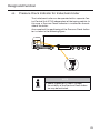
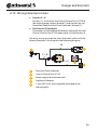
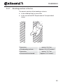
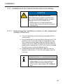
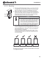
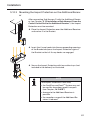
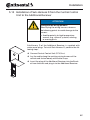
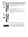
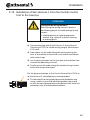
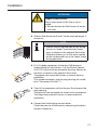
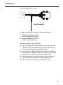
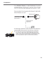
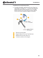
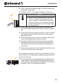
Installation 5.16.1 CPC as independent system Basic principle of the wiring: TR 15 TR 31 2 1 A plug-in connector is used for 2 wires respectively: ■■ Plug-in connector 1 (white): Wires are brown and white ■■ Plug-in connector 2 (black): Wires are red and black Proceed as follows for installation: Identify a suitable cable feedthrough behind the dashboard from the Display to the fuse box; components of the dashboard may have to be loosened for this (see operating manual of the vehicle). Lay Sub-Harness B behind the dashboard. Lay the open end from the dashboard to the fuse box. Secure the cable sufficiently with cable straps. Secure loosened parts of the dashboard again. In the fuse box, identify terminal 15 (ignition - IGN) and the terminal 31 (ground - GND). Pay attention to the special instructions in the vehicle operating manual. Lay Sub-Harness A from the fuse box to cables B and C. The integrated fuse remains in the wiring harness. 70