1
UM1892
User manual
Getting started with the X-CUBE-SUBG1 for WM-Bus
communications based on Sub-1 GHz RF expansion board
Introduction
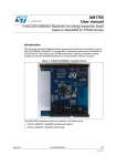
X-CUBE-SUBG1 provides a middleware example and demo application for the STM32 to
build applications using the SPSGRF-868 module based on the SPIRIT1 low data rate, low
power sub-1 GHz transceiver device. It is easily portable across different MCU families
thanks to STM32Cube.
This manual describes how to get started with the X-CUBE-SUBG1 software for a wireless
meter bus (WM-Bus) application.
The software provides implementation examples for STM32 Nucleo platforms equipped with
the X-NUCLEO-IDS01A4 expansion board using SPSGRF-868 module
The following demo examples are available for testing with the expansion board:
• WM-Bus: wireless metering bus demo
• Point-to-point communication protocol demo
This document explains the wireless metering bus demo.
May 2015
DocID027820 Rev 1
1/30
www.st.com
30
Contents
UM1892
Contents
1
2
3
4
5
2/30
What is STM32Cube? . . . . . . . . . . . . . . . . . . . . . . . . . . . . . . . . . . . . . . . . 4
1.1
STM32Cube overview . . . . . . . . . . . . . . . . . . . . . . . . . . . . . . . . . . . . . . . . 4
1.2
STM32Cube architecture . . . . . . . . . . . . . . . . . . . . . . . . . . . . . . . . . . . . . . 4
X-CUBE-SUBG1 software expansion for STM32Cube . . . . . . . . . . . . . . 6
2.1
Overview . . . . . . . . . . . . . . . . . . . . . . . . . . . . . . . . . . . . . . . . . . . . . . . . . . 6
2.2
Introduction to WM-Bus . . . . . . . . . . . . . . . . . . . . . . . . . . . . . . . . . . . . . . . 6
2.3
Architecture . . . . . . . . . . . . . . . . . . . . . . . . . . . . . . . . . . . . . . . . . . . . . . . . 9
2.4
Folder structure . . . . . . . . . . . . . . . . . . . . . . . . . . . . . . . . . . . . . . . . . . . . 10
2.5
APIs . . . . . . . . . . . . . . . . . . . . . . . . . . . . . . . . . . . . . . . . . . . . . . . . . . . . . .11
WM-Bus demo firmware . . . . . . . . . . . . . . . . . . . . . . . . . . . . . . . . . . . . . 12
3.1
WM-Bus application workspace . . . . . . . . . . . . . . . . . . . . . . . . . . . . . . . . 12
3.2
Running the demo board (X-NUCLEO-IDS01V4) . . . . . . . . . . . . . . . . . . 12
3.2.1
Programming the Nucleo board with firmware . . . . . . . . . . . . . . . . . . . . 12
3.2.2
WM-Bus application demonstration for X-NUCLEO-IDS01A4 . . . . . . . . 13
3.2.3
Installation sequence for X-NUCLEO-IDS01A4 . . . . . . . . . . . . . . . . . . . 14
3.2.4
Data communication sequence for X-NUCLEO-IDS01A4 . . . . . . . . . . . 14
Using the demo board with GUI . . . . . . . . . . . . . . . . . . . . . . . . . . . . . . . 15
4.1
GUI description . . . . . . . . . . . . . . . . . . . . . . . . . . . . . . . . . . . . . . . . . . . . . 15
4.2
Configuration window . . . . . . . . . . . . . . . . . . . . . . . . . . . . . . . . . . . . . . . . 15
4.3
Meter window . . . . . . . . . . . . . . . . . . . . . . . . . . . . . . . . . . . . . . . . . . . . . . 15
4.4
Monitoring window . . . . . . . . . . . . . . . . . . . . . . . . . . . . . . . . . . . . . . . . . . 16
4.5
Board configuration with PC GUI . . . . . . . . . . . . . . . . . . . . . . . . . . . . . . . 17
Hardware description . . . . . . . . . . . . . . . . . . . . . . . . . . . . . . . . . . . . . . . 23
5.1
STM32 Nucleo platform . . . . . . . . . . . . . . . . . . . . . . . . . . . . . . . . . . . . . . 23
5.2
X-NUCLEO-IDS01A4 expansion board . . . . . . . . . . . . . . . . . . . . . . . . . . 23
5.3
Software description . . . . . . . . . . . . . . . . . . . . . . . . . . . . . . . . . . . . . . . . . 25
5.4
Hardware setup . . . . . . . . . . . . . . . . . . . . . . . . . . . . . . . . . . . . . . . . . . . . 25
5.4.1
Hardware setup . . . . . . . . . . . . . . . . . . . . . . . . . . . . . . . . . . . . . . . . . . . 25
5.4.2
Setting up the board . . . . . . . . . . . . . . . . . . . . . . . . . . . . . . . . . . . . . . . 25
DocID027820 Rev 1
UM1892
Contents
5.4.3
Setting up the WM-Bus concentrator . . . . . . . . . . . . . . . . . . . . . . . . . . . 25
6
Acronyms and abbreviations . . . . . . . . . . . . . . . . . . . . . . . . . . . . . . . . . 27
7
References . . . . . . . . . . . . . . . . . . . . . . . . . . . . . . . . . . . . . . . . . . . . . . . . 28
7.1
8
Document conventions . . . . . . . . . . . . . . . . . . . . . . . . . . . . . . . . . . . . . . . 28
Revision history . . . . . . . . . . . . . . . . . . . . . . . . . . . . . . . . . . . . . . . . . . . 29
DocID027820 Rev 1
3/30
30
What is STM32Cube?
UM1892
1
What is STM32Cube?
1.1
STM32Cube overview
STMCube™ represents an original initiative by STMicroelectronics to ease developers' life
by reducing development effort, time and cost. STM32Cube covers the STM32 portfolio.
Version 1.x of STM32Cube includes:
STM32Cube Version 1.x includes:
• STM32CubeMX, a graphical software configuration tool that allows the generation of C
initialization code using graphical wizards.
• A comprehensive embedded software platform, delivered per series (such as
STM32CubeF4 for STM32F4 series).
– The STM32Cube HAL, an STM32 abstraction layer embedded software, ensuring
maximized portability across STM32 portfolio
– A consistent set of middleware components such as RTOS, USB, TCP/IP, graphics
– All embedded software utilities, including a full set of examples.
Information about STM32Cube is available on st.com at: http://www.st.com/stm32cube.
1.2
STM32Cube architecture
The STM32Cube firmware solution is built around three independent levels that can easily
interact with each other, as illustrated in the figure below:
Figure 1. Firmware architecture
4/30
DocID027820 Rev 1
UM1892
What is STM32Cube?
Level 0: This level is divided into three sub-layers:
• Board support package (BSP): this layer offers a set of APIs relative to the hardware
components in the hardware boards (audio codec, IO expander, touchscreen, SRAM
driver, LCD drivers, etc.) and composed of two parts:
– Component: the driver relative to the external device on the board and not related to
the STM32. The component driver provides specific APIs to the BSP driver external
components and could be portable to any other board.
– BSP driver: permits the linking of the component driver to a specific board and
provides a set of user friendly APIs. The API naming rule is BSP_FUNCT_Action():
ex. BSP_LED_Init(),BSP_LED_On()
It is based on a modular architecture allowing it to be easily ported to any hardware by
implementing the low level routines.
• Hardware abstraction layer (HAL): this layer provides the low level drivers and the
hardware interfacing methods to interact with the upper layers (application, libraries and
stacks). It provides generic, multi instance and functionality-oriented APIs which permit
offloading of the user application implementation by providing a ready-to-use process. As
an example, for the communication peripherals (I2S, UART, etc.) it provides APIs allowing
initialization and configuration of the peripheral, management of data transfer based on
polling, interrupt or DMA process, and management of communication errors that may
arise during communication. The HAL driver APIs are split into two categories, generic
APIs which provide common and generic functions to all the STM32 series, and extension
APIs which provide specific and customized functions for a specific family or a specific
part number.
• Basic peripheral usage examples: this layer encloses the examples build over the STM32
peripheral using only the HAL and BSP resources.
Level 1: This level is divided into two sub-layers:
• Middleware components: set of libraries covering USB host and device libraries,
STemWin, FreeRTOS, FatFS, LwIP, and PolarSSL. Horizontal interaction between the
components of this layer is done directly by calling the feature APIs, while the vertical
interaction with the low level drivers is done through specific callbacks and static macros
implemented in the library system call interface. For example, the FatFs implements the
disk I/O driver to access microSD drive or the USB mass storage class.
• Examples based on the middleware components: each middleware component comes
with one or more examples (also called applications) describing how to use it. Integration
examples that use several middleware components are provided as well.
Level 2: This level is composed of a single layer which is a global real-time and graphical
demonstration based on the middleware service layer, the low level abstraction layer and
the basic peripheral usage applications for board-based functionalities.
DocID027820 Rev 1
5/30
30
X-CUBE-SUBG1 software expansion for STM32Cube
UM1892
2
X-CUBE-SUBG1 software expansion for STM32Cube
2.1
Overview
X-CUBE-SUBG1 is a software package that expands the functionality provided by
STM32Cube.
The key features of the package are:
• Demo example of Point-to-point (P2P) communication to transfer data from one node to
another
• Middleware to build applications for WM-Bus (wireless metering bus)
• Easy portability across different MCU families thanks to STM32Cube
• Free user-friendly license terms
• Example implementation available on board X-NUCLEO-IDS01A4 (868 MHz) plugged on
top of one NUCLEO-L053R8 or NUCLEO-F401RE
Using the software details explained in this document, the following applications can also be
developed:
• Automatic meter reading
• Gas meter reading
• Water meter reading
• Electricity meter reading
• Heat meter reading
2.2
Introduction to WM-Bus
The M-Bus (meter bus) is a common standard used for AMR implementation, for remote
energy meter reading, and is based on European standards EN 13757-2 physical and link
layer, and EN 13757-3 application layer. The M-Bus interface is made for communication on
two wires, twisted cable, making it very cost effective. In the M-Bus, it is possible use any
kind of network topology (linear, star, etc.), except ring network, capable of achieving long
distance communication. When interrogated, the meters send the data to a concentrator
that can render them available locally or remotely. A radio variant of M-Bus, wireless M-Bus,
is also specified in EN 13757-4.
The wireless meter bus is an open standard for automatic meter reading at RF sub 1-GHz
level. The relevant standards documents are:
• European standard prEN13757-4:2011 Wireless meter readout
• European standard EN13757-3:2004 Dedicated application layer (in common with MBus)
• ETSI EN 300 220 v2.3.1
The wireless M-Bus firmware stack is based on EN 13757-4:2011.10 (communication
systems for meters and remote reading of meters - Part 4: Wireless meter readout (Radio
meter reading for operation in SRD bands)). This European standard specifies the
requirements for parameters for the physical and the link layer for systems using radio to
read remote meters. The primary focus is to use the short range device (SRD) unlicensed
telemetry bands. The standard encompasses systems for walk-by, drive-by and fixed
installations:
6/30
DocID027820 Rev 1
UM1892
X-CUBE-SUBG1 software expansion for STM32Cube
Figure 2. Basic wireless M-Bus architecture
*63*6*
The wireless M-Bus standard is defined by the European standard EN 13757-4 for physical
and data link layers. The application layer is defined by EN 13757-3 standard.
There are different types of devices:
1.
Meter
2.
Concentrator/ read-out device
3.
Router
The standard defines the communication between remote meters and mobile readout
devices, stationary receivers, data collectors, etc. The typical application scenario is shown
below:
Figure 3. Final application scenario
*63*6*
STMicroelectronics has developed a wireless M-Bus firmware stack implementation, based
on ST's dual chip platform, SPIRIT1 RF sub-1 GHz transceiver and the STM32 NUCLEOL053R8 (ARM Cortex-M0+) / STM32L15 ultra low power (ARM Cortex-M3) microcontroller.
SPIRIT1:
The SPIRIT1 is a very low-power and high performance RF transceiver, addressing RF
wireless applications in the sub-1 GHz band. It is designed to operate at 169, 315, 433, 868,
and 915 MHz. It supports the following modulation: 2-FSK, GFSK, MSK, OOK, and ASK.
The air data rate is programmable from 1 to 500 kbps, depending on the selected
modulation. It has an integrated SMPS which allows very low power consumption: 9 mA in
Rx and 21 mA in Tx mode at +11 dBm. It uses a very small number of discrete external
DocID027820 Rev 1
7/30
30
X-CUBE-SUBG1 software expansion for STM32Cube
UM1892
components and integrates a configurable baseband modem, which supports data
management, modulation, and demodulation. The data management handles the data in
the proprietary fully programmable packet format also allows the M-Bus standard
compliance format (all performance classes). The SPIRIT1 is native HW supporting the low
level of WM-Bus PHY protocol.
Ultra low power 32-bit MCU ARM-based Cortex-M0+, STM32L053x6/8
The ultra low power STM32L053x6/8 incorporates the connectivity power of the universal
serial bus (USB 2.0 crystal-less) with the high-performance ARM Cortex™-M0+ 32-bit RISC
core operating at a 32 MHz frequency, a memory protection unit (MPU), high-speed
embedded memories (up to 64 Kbytes of Flash program memory, 2 Kbytes of data
EEPROM and 8 Kbytes of RAM) plus an extensive range of enhanced I/Os and peripherals.
The STM32L053x6/8 devices provides high power efficiency for a wide range of
performance. It is achieved with a large choice of internal and external clock sources, an
internal voltage adaptation and several low power modes.
The STM32L053x6/8 devices offer several analog features, one 12-bit ADC, one DAC, two
ultra low power comparators, several timers, one low-power timer (LPTIM), three generalpurpose 16-bit timers and one basic timer, one RTC and one SysTick which can be used as
time bases. They also feature two watchdogs, one watchdog with independent clock and
window capability and one window watchdog based on bus clock.
Moreover, the STM32L053x6/8 devices embed standard and advanced communication
interfaces: up to two I²Cs, two SPIs, two I2S, three USARTs and a crystal-less USB. The
devices offer up to 24 capacitive sensing channels to easily add touch sensing functionality
to any application.
In this user manual, STMicroelectronics’ WM-Bus application layer is explained:
Figure 4. WM-Bus
*63*6*
The WM-Bus protocol stack is developed on ST's dual chip platform. The SPIRIT1
implements just a part of the WM-Bus physical layer, the PHY and LINK firmware stack
layers are implemented in STM32Lxx.
The firmware partitioning between STM32 available on Nucleo boards and SPIRIT1 device
is explained below.
STM32 MCU:
• WM-Bus application layer
– Wireless M-Bus application layer partially implements the EN13757-3.
8/30
DocID027820 Rev 1
UM1892
X-CUBE-SUBG1 software expansion for STM32Cube
• WM-Bus link layer
– MAC packet and CRC handling
– Encryption/ decryption initiate/read.
• WM-Bus PHY
– Init PHY for WM-Bus
– Interrupt services
Figure 5. SPIRIT1 role
*63*6*
SPIRIT1 role:
• WM-Bus modes
• Header, sync and trailer fields
• Manchester/3-out-of-6-encoding
• Sync detection
• Tx and RX FIFO
Note:
STM32 NUCLEO-L053R8 supports WM-Bus METER implementation only
2.3
Architecture
This software is an expansion for STM32Cube, and as such it fully complies with the
architecture of STM32Cube and expands it in order to enable development of applications
using X-NUCLEO-IDS01A4 boards hosting the SPIRIT1 device module. Please see the
previous chapter for an introduction to the STM32Cube architecture.
The software is based on the STM32CubeHAL, the hardware abstraction layer for the
STM32 microcontroller. The package extends STM32Cube by providing a board support
package (BSP) for the SPIRIT1 expansion board and some example firmware for P2P
communication and middleware example of WM-Bus.
The software layers used by the application software to access and use the SPIRIT1
expansion board are as follows:
• STM32Cube HAL layer: The HAL driver layer provides a generic multi instance simple set
of APIs (application programming interfaces) to interact with the upper layers (application,
libraries and stacks). It is composed of generic and extension APIs. It is directly built
around a generic architecture and allows the layers that are built upon, such as the
middleware layer, to implement their functionalities without dependencies on the specific
DocID027820 Rev 1
9/30
30
X-CUBE-SUBG1 software expansion for STM32Cube
UM1892
hardware configuration for a given microcontroller unit (MCU). This structure improves
library code reusability and guarantees easy portability to other devices.
• Board support package (BSP) layer: The software package needs to support the
peripherals on the STM32 Nucleo board apart from the MCU. This software is included in
the board support package (BSP). This is a limited set of APIs which provides a
programming interface for certain board specific peripherals, e.g. the LED, the user
button, etc. The BSP firmware layer of the X-NUCLEO-IDS01A4 board contains set of
APIs related to the hardware components. This is composed of two parts:
a)
Component: As defined in STM32Cube this is the driver related to the external
device on the board and not related to the STM32. The SPIRIT1 BSP driver is
called as the firmware component.
The SPIRIT1 component driver provides specific APIs and can be ported and
used on any board.
b)
BSP driver: Enables the component driver to be linked to a specific board and
provides a set of user-friendly APIs.
• Middleware: This layer includes the libraries for WM-Bus, USB, touch sensing, etc.
This document explains the WM-Bus middleware for X-NUCLEO-IDS01A4
• Application layer:
This layer provides example of Point-to-point communication. This example is discussed
in a separate document.
The following figure outlines the software architecture of the package:
Figure 6. X-CUBE-SUBG1 software architecture
*63*6*
2.4
Folder structure
This section provides an overview of the package folder structure.
Figure 7 outlines the architecture of the package.
10/30
DocID027820 Rev 1
UM1892
X-CUBE-SUBG1 software expansion for STM32Cube
Figure 7. X-CUBE-SUBG1 package folders structure
The following folders are included in the software package:
– Documentation: this folder contains a compiled HTML file generated from the source
code and documenting in detail the software components and APIs.
– Drivers: this folder contains the HAL drivers, the board specific drivers for each
supported board or hardware platform, including the on-board component ones and
the CMSIS layer which is a vendor-independent hardware abstraction layer for the
Cortex-M processor series.
– Middlewares: this folder contains libraries for WM-Bus.
– Projects: this folder contains a sample application used for WM-Bus and P2P
firmware examples for the NUCLEO-L053R8 and NUCLEO-F401RE platforms with
three development environments (IAR Embedded Workbench for ARM, RealView
Microcontroller Development Kit (MDK-ARM), Atollic TrueSTUDIO® for ARM).
– Utilities: this folder contains a folder called “PC_software” in which a Windows PC
utility is provided. The utility is for WM-Bus usage and testing.
2.5
APIs
Detailed technical information about the APIs is available in a compiled HTML file located
inside the “Documentation” folder of the software package, where all the functions and
parameters are fully described.
DocID027820 Rev 1
11/30
30
WM-Bus demo firmware
3
UM1892
WM-Bus demo firmware
The following section explains how the demo firmware is implemented, the user settings
and configurations available and how to modify the firmware for other application usage.
3.1
WM-Bus application workspace
X-NUCLEO-IDS01V4 can be programmed only as a WM-Bus meter. The dedicated
workspace is:
…\Projects\[Board Name]\Applications\WMBusStandalone
For example, for STM32L053R8-Nucleo boards, the location of the workspace is:
...\Projects\Multi\Applications\WMBusStandalone
STEVAL-IKR00xVx/STEVAL-IDS001Vx boards are used as a concentrator device for the
WM-Bus application demo.
3.2
Running the demo board (X-NUCLEO-IDS01V4)
The following are the steps required to run the basic demo of the WM-Bus application.
3.2.1
Programming the Nucleo board with firmware
The steps to program the Nucleo board with WM-Bus firmware are:
12/30
1.
Ensure the use of the appropriate toolchain IDE
2.
The workspace is provided for the WM-Bus meter application at 868 MHz frequency
band
3.
Connect Nucleo board to a PC using a USB-Mini B-type cable
4.
Flash the Nucleo Board with WMBusStandalone workspace
5.
Make sure that the meter and concentrator devices are programmed with the same
configuration, i.e. if the meter is programmed with the 868 MHz configuration, then the
same configuration should be used at the concentrator side also
DocID027820 Rev 1
UM1892
WM-Bus demo firmware
Table 1. WM-Bus modes summary and support
Mode
Communication
Frequency band to choose
Mode supported
S1
Unidirectional
868 MHz
Yes
S1-m
Unidirectional
868 MHz
Yes
S2
Bidirectional
868 MHz
Yes
T1
Unidirectional
868 MHz
Yes
T2
Bidirectional
868 MHz
Yes
R2
Bidirectional
868 MHz
Yes
N1
Unidirectional
169 MHz
No
N2
Bidirectional
169 MHz
No
6.
Connect the concentrator to WM-Bus PC GUI. Follow the steps described to use the
GUI.
7.
Different meter types are supported in WM-Bus. For example:
a)
Electricity meter=0x02
b)
Gas meter=0x03
c)
Heat meter=0x04 and so on.
The user can set the meter type by changing the following in file “radio_hal.c”, as shown in
Figure 8 below:
Figure 8. User settings in firmware
*63*6*
3.2.2
WM-Bus application demonstration for X-NUCLEO-IDS01A4
The WM-Bus application is demonstrated in two steps:
Step 1. Installation sequence
DocID027820 Rev 1
13/30
30
WM-Bus demo firmware
UM1892
Step 2. Data communication sequence.
3.2.3
Installation sequence for X-NUCLEO-IDS01A4
As the first step, the meter must be connected to the concentrator.
Figure 9. WM-Bus installation request using the SPIRIT1 expansion boards
&RQFHQWUDWRU
0HWHU
& RQQHFW
FRQFHQWUDWRU
SRZHU V XSSO\
ERDUG
WR
/( ' '/ ZLOO WXUQ 21 FRQILUPLQJ
,QVWDOO
UHTXHVW
LV
V XFF HV VIXOO\
FRPSOHWHG
6 HQG LQV WDOODWLRQ UHTXHVW IURP PHWHU E\
SUHVV LQJ
86 ( 5 % XWWRQ
RQ 1XFOHR
% RDUG
8V HU /( ' RQ 6 3 ,5 ,7 H[SDQV LRQ % RDUG
ZLOO WXUQ 21 FRQILUPLQJ ,QV WDOO UHTXHVW LV
V HQW
*63*6*
3.2.4
Data communication sequence for X-NUCLEO-IDS01A4
The meter must be connected to the concentrator prior to this step.
Figure 10. WM-Bus data communication with the SPIRIT1 expansion boards
&RQFHQWUDWRU
0HWHU
3 UHVV 6 : WRFRQILJXUHFRQFHQWUDWRU
LQGDWDFRPPXQLFDWLRQPRGH/( '
'/ZLOO EH21
,ILQV WDOODWLRQLV V XFFH VV IXOPHWHUV HQGV GDWDHYHU\PLQXWHV 8V HU/( 'RQ
6 3 ,5 ,7 H[SDQV LRQERDUGV ZLOO WRJJOH
7 KHGDWDUHFH LYHGZLOO EH
FRQILUPHGE\WRJJOLQJ/( ''/
*63*6*
14/30
DocID027820 Rev 1
UM1892
4
Using the demo board with GUI
Using the demo board with GUI
The demo board Flashed with concentrator firmware must be connected to PC-GUI through
the USB port.
4.1
GUI description
The wireless M-Bus application GUI has following windows:
4.2
1.
Monitoring window
2.
Configuration window
3.
Meters window
4.
Sniffer window
Configuration window
The wireless M-Bus devices can be configured using this window. The configurable
parameters are: device type, header length, wireless M-bus mode, Manufacturer ID, RF
power, time, typical response time, etc. The current configuration can also be retrieved here.
Upon pressing the connection button, the board type and WM-Bus mode parameters
retrieved.
Figure 11. WM-Bus configuration window
4.3
Meter window
The meter window can be used to add meters, update meter attributes and delete meters
from the database. This window is available only in case of concentrator.
DocID027820 Rev 1
15/30
30
Using the demo board with GUI
UM1892
Figure 12. Meter window
4.4
Monitoring window
The monitoring window offers view of meter reading and also the history of the meters.
There is a provision for exporting the meter reading database to *.csv format.
16/30
DocID027820 Rev 1
UM1892
Using the demo board with GUI
Figure 13. Monitoring window
4.5
Board configuration with PC GUI
In order to support the GUI, the board must be programmed with the WM-Bus_SDK
firmware as explained in Section 3.2: Running the demo board (X-NUCLEO-IDS01V4).
DocID027820 Rev 1
17/30
30
Using the demo board with GUI
1.
UM1892
After launching the GUI, connect the board to the PC using the top-left icon. The GUI
will ask the user to select the serial port for the device. Upon successful connection, the
“Connection successful” window will appear.
Figure 14. Select COM port for device
Figure 15. Connection successful
2.
18/30
The concentrator configuration can be retrieved using the “Receive all” icon. Go to
configuration window, which shows the current configuration of the concentrator board.
DocID027820 Rev 1
UM1892
Using the demo board with GUI
Also the entire configuration can be sent to the board with the “Send all” icon. Refer to
the screenshot below to identify the different icons on the GUI.
Figure 16. Configuration window
3.
User can monitor the meter data received on concentrator side using monitoring
window by clicking on “Auto Refresh” button.
Figure 17. GUI monitoring window
DocID027820 Rev 1
19/30
30
Using the demo board with GUI
UM1892
The meter data is displayed in the GUI, as shown below:
Figure 18. GUI monitoring window with meter data
4.
A new meter can be added to or deleted from the concentrator database using the
“Meter Window”. This window is useful in a cases where encryption is enabled. The
window displays the concentrator database in “Edit Meter” section. The concentrator
database contains meter IDs and corresponding encryption keys.
Default values (meter ID and encryption key) for three meters are stored in the concentrator
database. If encryption is enabled and any of these three meters comes online, the
concentrator will talk to them using the encryption key allotted to them. The same encryption
keys are also preset in the meter firmware for:
a)
DEVICE_METER_TYPE = 0x02 (electricity meter)
b)
DEVICE_METER_TYPE = 0x03 (gas meter)
c)
DEVICE_METER_TYPE = 0x04 (heat meter)
The concentrator database can contain values (meter ID and encryption key) for ten meters,
at most.
The user can add a new meter to the concentrator database through the “Add Meter”
section. The user must enter the meter ID, device type, encryption key and entry no. (the
entry no. corresponds to sequential EEPROM addresses of the concentrator data base).
After entering all details for the meter, press the “Add” button.
20/30
DocID027820 Rev 1
UM1892
Using the demo board with GUI
Figure 19. A view of the concentrator database
Figure 20. Adding a new meter to the concentrator database
DocID027820 Rev 1
21/30
30
Using the demo board with GUI
UM1892
Figure 21. The new meter added to the database
5.
22/30
Delete a meter entry by selecting the row corresponding to that meter in the “Edit
Meter” section and click the “Delete” button.
DocID027820 Rev 1
UM1892
5
Hardware description
Hardware description
This section describes the hardware components needed for developing a SPIRIT1-based
application.
The following subsections describe the individual components.
For further details, please refer to ST user manual UM1872 “Getting started with the Sub-1
GHz expansion board based on the SPSGRF-868 and SPSGRF-915 modules for STM32”.
5.1
STM32 Nucleo platform
The STM32 Nucleo boards provide an affordable and flexible way for users to try out new
ideas and build prototypes with any of the STM32 microcontroller lines. The Arduino™
connectivity support and ST Morpho headers make it easy to expand the functionality of the
STM32 Nucleo open development platform with a wide choice of specialized expansion
boards. The STM32 Nucleo board does not require any separate probe as it integrates the
ST-LINK/V2-1 debugger/programmer. The STM32 Nucleo board comes with the STM32
comprehensive software HAL library together with various packaged software examples.
Information about the STM32 Nucleo boards is available on www.st.com at
http://www.st.com/stm32nucleo
Figure 22. STM32 Nucleo board
5.2
X-NUCLEO-IDS01A4 expansion board
The X-NUCLEO-IDS01A4 is an evaluation kit that provides a platform for testing the
features and capabilities of the SPSGRF module based on the SPIRIT1 low data rate, low
power sub-1 GHz transceiver device.
The expansion board features on-board SPI EEPROM to save parameters, and an LED for
user interface.
DocID027820 Rev 1
23/30
30
Hardware description
UM1892
Figure 23. X-NUCLEO-IDS1Ax SPIRIT1 expansion board
Information about the X-NUCLEO-IDS01A4 expansion board is available on www.st.com at
http://www.st.com/x-nucleo
Figure 24. SPIRIT1 expansion board connected to STM32 Nucleo board
24/30
DocID027820 Rev 1
UM1892
5.3
Hardware description
Software description
The following software components are needed in order to setup a suitable development
environment for creating applications for the STM32 Nucleo equipped with the SPIRIT1
expansion board:
• X-CUBE-SUBG1: an expansion for STM32Cube dedicated to SPIRIT1 application
development. The X-CUBE-SUBG1 firmware and related documentation is available on
st.com.
• Development tool-chain and compiler: The STM32Cube expansion software supports the
following three environments:
– IAR Embedded Workbench for ARM® (EWARM) toolchain + ST- LINK
– RealView Microcontroller Development Kit (MDK-ARM) toolchain + ST-LINK
– System Workbench for STM32 (SW4STM32) + ST-Link
5.4
Hardware setup
This section describes the hardware and software setup procedures. It also describes the
system setup needed for the above.
5.4.1
Hardware setup
The following hardware components are needed:
5.4.2
1.
One STM32 Nucleo Development platform (suggested order code: either NUCLEOF401RE or NUCLEO-L053R8)
2.
One SPIRIT1 expansion board (order code: X-NUCLEO-IDS01A4 (868 MHz)
3.
One USB type A to Mini-B USB cable to connect the STM32 Nucleo to the PC
Setting up the board
Follow these steps to set up the board:
5.4.3
1.
Check that the jumper on the J1 connector is connected. This jumper provides the
required voltage to the devices on the board
2.
Connect the X-NUCLEO-IDS01A4 to the Nucleo board from the top, as shown in
Figure 22
3.
Power the Nucleo board using the Mini-B USB cable
4.
Program the firmware in the STM32 on the Nucleo board using the firmware example
provided
5.
Reset the MCU board using the Reset button available on the Nucleo board
6.
The evaluation kit is ready for use
Setting up the WM-Bus concentrator
The WM-Bus firmware demo requires two demo boards to run the basic application
example. One board is used as a concentrator device and another is used as a meter
device. Table 2 provides the list of evaluation boards which are used to run the WM-Bus
example application:
DocID027820 Rev 1
25/30
30
Hardware description
UM1892
Table 2. Demo board description
Demo board
WM-Bus device type
STEVAL- IKR002Vx
METER / CONCENTRATOR
STEVAL- IDS001Vx
CONCENTRATOR
STEVAL- IKR001Vx
METER / CONCENTRATOR
X-NUCLEO-IDS02Ax
METER
Take care to use the correct board for the matching RF frequency. For example, for the WMBus to work with X-NUCLEO-IDS01A4, use the 868 MHz board.
26/30
DocID027820 Rev 1
UM1892
6
Acronyms and abbreviations
Acronyms and abbreviations
Table 3. Acronyms
Acronym
Description
AMR
Automatic meter reading
BSP
Boot support package. Generally refers to the hardware interface layer
EEPROM
Electrically erasable programmable read only memory
GHz
Giga Hertz
GUI
Graphical user interface
HAL
Hardware abstraction layer
LED
Light emitting diode
MCU
Microcontroller unit
P2P
Point-to-point communication
PC
Personal computer
RF
Radio frequency communication
SPI
Serial peripheral interface
USB
Universal serial bus
WM-Bus
WSN
Wireless metering bus
Wireless sensors network
DocID027820 Rev 1
27/30
30
References
7
UM1892
References
[1] SPIRIT1 device datasheet
[2] SPSGRF module datasheet
[3] STM32 and Nucleo boards datasheets/data briefs
[4] UM1872 Getting started with the Sub-1 GHz expansion board based on the SPSGRF868 and SPSGRF-915 modules for STM32
7.1
Document conventions
• SPIRIT1 expansion boards: All references to these boards refer to the X-NUCLEOIDS01A4 (868 MHz) in this document. The WM-Bus standard specifies 868 MHz as the
communication frequency
• STM32 Nucleo board: This term is used for the reference of NUCLEO-L053R8 boards
and NUCLEO-F401RE, unless otherwise specified
• The firmware described in this document is developed and tested using the NUCLEOL053R8 and X-NUCLEO-IDS01A4 boards. The demo firmware can easily be ported to
other NUCLEO or SPIRIT1 boards by making changes to the BSP layer
• Node: This term is used for the combination of STM32 Nucleo board and SPIRIT1
expansion board when used in a connected network
28/30
DocID027820 Rev 1
UM1892
8
Revision history
Revision history
Table 4. Document revision history
Date
Revision
29-May-2015
1
Changes
Initial release.
DocID027820 Rev 1
29/30
30
UM1892
IMPORTANT NOTICE – PLEASE READ CAREFULLY
STMicroelectronics NV and its subsidiaries (“ST”) reserve the right to make changes, corrections, enhancements, modifications, and
improvements to ST products and/or to this document at any time without notice. Purchasers should obtain the latest relevant information on
ST products before placing orders. ST products are sold pursuant to ST’s terms and conditions of sale in place at the time of order
acknowledgement.
Purchasers are solely responsible for the choice, selection, and use of ST products and ST assumes no liability for application assistance or
the design of Purchasers’ products.
No license, express or implied, to any intellectual property right is granted by ST herein.
Resale of ST products with provisions different from the information set forth herein shall void any warranty granted by ST for such product.
ST and the ST logo are trademarks of ST. All other product or service names are the property of their respective owners.
Information in this document supersedes and replaces information previously supplied in any prior versions of this document.
© 2015 STMicroelectronics – All rights reserved
30/30
DocID027820 Rev 1