1
Z E K T O R
Ho m e T h e a t e r Switches
Digital Video / Component Video / Multichannel Audio
CVS4
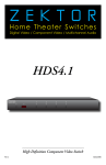
High Definition Component Video Switch
Rev 1
02/28/2006
What’s Inside
Contents
Thank you for your purchase of your C VS4 H igh D efinition Component
Video Switch.
What’s Inside...................................... 1
An Overview of the CVS4.. ................... 3
Easy, Simple, Instructions!.................. 5
Three Simple Steps to a Remote!......... 7
Controlling the Front Panel Lights...... 9
Adjusting the Front Panel Intensity... 11
Setting the Initial Power On State..... 13
Disabling Front Panel or Remote.. ..... 15
Ever y care has been taken to assure you of a successful installation
and subsequent operations of your new C VS4 video switch, however
should something go wrong, and war rant y repair wor k is needed, we
request that you hold on to the or iginal pack aging mater ials.
Please take this time to ver ify the contents of the C VS4 box.
The following should be included:
1.
2.
3.
C VS4
Power Supply M odule
This User ’s M anual
I f anything is missing please get in touch with us as soon as possible
so that we can cor rec t the situation.
Resetting to Factory Defaults.. .......... 17
The RS-232 Port................................ 18
K.I.S.S.™ (Keep It Simple Serial!™)..... 19
The Rear Panel IR Jack...................... 21
Specifications................................... 23
Warranty Policy................................ 24
Contact Information......................... 25
ii
CVS4 Component Video Switch
CVS4 Component Video Switch
An Overview of the CVS4
Front Panel Controls:
Front Panel
1
2
1
2
3
4
1.
2.
3.
4.
5.
6.
Power I ndicator. Lights up in standby mode.
S elec tion LEDs. I ndicate cur rently selec ted inputs.
I nput S elec tion Buttons.
I nfrared R emote S ensor Window.
I nfrared R eceived I ndicator. Flashes when IR is received.
Power Toggle Button.
3
4
5
6
1
2
3
4
5
6
L/H
C/V
1
R/V
L/H
C/V
2
Y/G
Pb/B
Pr/R
R/V
L/H
C/V
3
Y/G
Pb/B
Pr/R
R/V
L/H
C/V
Pb/B
Pr/R
L/H
C/V
1
2
Y/G
Pb/B
Pr/R
DIGITAL
AUDIO
Y/G
Pb/B
Pr/R
4
OUT
OUT
1
IR / Z-IN
Z-OUT
8.
2
3
4
OUT
9VDC
7
8
CVS4 Component Video Switch
4.
5.
6.
7.
RS-232
3
OUT
4
Y/G
R/V
1.
2.
3.
Rear Panel
R/V
Rear Panel Connections:
Analog I nputs. Each input consists of six equivalent channels. The channels are colored and labeled for convenience,
however all six channels are of equivalent bandwidth and
func tionalit y, and may be interchanged as desired.
Analog Outputs.
Digital Audio I nputs. Each input has an associated digital
audio channel with both a Coax and an Optical connec tion.
Only one of the t wo t ypes of inputs can be ac tive at any
time. The C VS4 will auto -selec t bet ween the t wo t ypes of
signals. I f a signal is supplied to both the Coax and Optical
inputs, the Coax signal is given pr ior it y.
IR I nput. Accepts modulated or unmodulated IR signals.
RS -232 Por t.
Z- OUT cur rently unused, reser ved for future use.
DC Power Jack Connec tor. Plug in the supplied power
adapter into this jack .
Digital Audio Outputs. All digital audio inputs are automatically conver ted to both Coax and Optical outputs. All three
outputs are available at all times, and are all individually
buffered to allow dr iving three different digital audio de vices simultaneously.
CVS4 Component Video Switch
Step 1: Make the appropriate connections.
Easy, Simple, Instructions!
To
Composite
Monitor
w/Analog
Audio
R/V
L/H
C/V
R/V
1
L/H
C/V
2
Y/G
Pb/B
Pr/R
R/V
L/H
C/V
3
Y/G
Pb/B
Pr/R
R/V
L/H
C/V
Pb/B
Pr/R
L/H
1
C/V
Y/G
Pb/B
Pr/R
Y/G
Pb/B
Pr/R
4
To
DVD
OUT
OUT
1
IR / Z-IN
2
Projector
or
Monitor
To DVD
Digital Audio
•
Z-OUT
3
4
OUT
To
Cable Box
Digital Audio To Game
Console
Digital Audio
To
To
Game
Console
Step 1...
RS-232
3
DIGITAL
AUDIO
Unused
Input
To
Cable
Box
2
OUT
4
Y/G
R/V
To Home Theater
Receiver’s Digital
Audio Input
9VDC
To Power
Module
Step 2: Press buttons to select an input.
1
2
3
•
•
•
4
Use the analog input connec tions to switch component
video / composite video / analog audio or any combination
of the above signals to the C VS4’s analog output connec tors. Use the digital audio connec tors to switch digital audio signals, with full for mat conversion bet ween the optical
and coax digital audio for mats.
I f using a hardwired IR controller to operate the C VS4, connec t the controller IR cable to the IR / Z-IN jack .
I f using a PC (or other ser ial controller), connec t it to the
RS -232 por t using a standard ser ial cable.
Plug the power module into the C VS4, and plug the module
into a standard A.C. wall receptacle. The standby LED will
light up.
Step 2...
•
•
Step 3: Or use nearly ANY remote to select an input.
1
POWER
1
2
4
5
3
6
7
8
9
+
_
VOL
CH
3
4
Turn to the next chapter for simple instructions
on how to setup the CVS4 for use with
any existing remote!
0
+
_
2
CVS4 Component Video Switch
To switch bet ween any of the four inputs, simply press the
button for the desired input. I f the C VS4 is in the standby,
it will tur n on. The C VS4 will then switch to the selec ted
input, and the associated LED will light to indicate this.
To place the C VS4 back into the standby mode, press and
release the Power Toggle button. The channel LEDs will all
go blank , and the standby LED will light up. Press the Power
Toggle button again to re -selec t the previously selec ted
input.
Step 3...
•
•
•
Use nearly any remote to control your C V S4!
Using any remote to operate the C VS4 is a simple matter of
pair ing up the C VS4 with the remote. The remote doesn’t
have to be a universal remote (although it can be), any re mote from an old T V or VCR will wor k just fine.
Using Zektor ’s exclusive I ntelligent-IR™, setup is easy! The
C VS4 does all the wor k!
Turn to the nex t chapter for simple instruc tions
on how to pair up the C VS4 with any remote!
CVS4 Component Video Switch
Step 1: Put the CVS4 into the Setup Mode
1
2
Three Simple Steps to a Remote!
3
4
The C VS4 features Zektor ’s Exclusive I ntelligent-IR™, and with ver y
few exceptions can be setup to use any remote you can point at it!
Press and hold the Power Button for 4 secs.
The standby LED will blink wildly, and the
selection LEDs will start sequencing to the
right. (You’ll know it when it happens!)
Step 2: Press the ‘1’ button for Intelligent-IR™ learning
1
2
Once the ‘1’ button
is pressed...
3
4
...the standby LED will flash slower,
and all the other LEDs will turn off.
Pick a remote, any remote!
•
•
Step 1: Put the CVS4 into the Setup Mode
•
•
POWER
1
2
3
4
5
6
7
8
9
•
+
_
VOL
CH
4
Press the following sequence of buttons on
your remote control:
•
CVS4 Component Video Switch
On your remote control, press the following buttons, in the
following order :
Power 1 2 3 4 8 9
That ’s it! The C VS4 will retur n to the state it was in before
setup, and will now wor k with your new remote!
The new control buttons on your remote are...
Power
1 - 4
8
9
Power 1 2 3 4 8 9
0
+
_
3
There are many options available in the setup mode, but for
now all we’re interested in is the I ntelligent-IR™ lear ning
mode. This is selec ted by pressing the ‘1’ button.
Once the ‘1’ button is pressed, the standby LED will flash
slower and all the other LEDs will tur n off. The C VS4 is
now waiting for new IR codes to be sent from your remote
control.
Step 3: Teach the CVS4 your new remote control codes
Step 3: Teach the CVS4 its new IR codes
2
The C VS4 is placed into the setup mode by pressing and
holding the Power button for about 4 seconds.
Step 2: Select the Intelligent-IR™ Learn Mode
•
1
Star t by pick ing the remote you’d like to use with the C VS4.
I f the remote you plan on using is not programmable (for
instance, from an old T V ), sk ip the nex t step.
I f you plan on using a universal remote, star t by setting it
up as a remote for a T V or VCR that you do not own. (For
instance if you don’t own a S ony T V, setup your universal
remote to control a S ony T V.)
That’s it! The CVS4 now operates with your
new remote control!
Note:
Toggles the C VS4’s power.
S elec ts inputs 1 through 4.
Tur ns on the C VS4 (Discrete ON)
Tur ns off the C VS4 (Discrete OFF).
All remote control codes are saved in non-volatile
memor y and will not be lost during a power failure.
CVS4 Component Video Switch
Step 1: Place the CVS4 into the Setup Mode
1
2
3
Controlling the Front Panel Lights
4
There are four different front panel light modes available on the
C VS4. They are:
Press and hold the Power Button for 4 secs.
The standby LED will blink wildly, and the
selection LEDs will start sequencing to the
right.
•
•
•
•
Note:
Step 2: Select “Lighting Mode” option
1
2
3
automatically fade from br ight to dim
inac tivit y.
are always at the br ight level.
are always at the dim level.
are tur ned off.
The intensities of the both the br ight and dim levels can be
adjusted as well, this is explained in the nex t chapter.
To change the front panel lighting mode...
Step 1: Enter the Setup Mode
4
•
After ‘3’ is pressed, the standby
LED continues to flash, and the
front panel will display the current Light Mode setting.
The C VS4 is placed into the setup mode by pressing and
holding the Power button for about 4 seconds.
Step 2: Select the Lighting Mode option
•
•
Step 3: Choose a new lighting mode
1
Front panel lights
af ter 4 seconds of
Front panel lights
Front panel lights
Front panel lights
2
3
Press the ‘3’ button to selec t the “Lighting M ode” option.
The front panel selec tion LEDs now indicate the cur rently
selec ted light mode as follows:
I f ‘1’ is lit, then front panel lights are always off.
I f ‘2’ is lit, then front panel lights are always dim.
I f ‘3’ is lit, then front panel lights are always br ight.
I f ‘4’ is lit, then front panel lights auto -fade from br ight to
dim af ter 4 seconds of inac tivit y.
Step 3: Choose a new lighting mode
4
Auto-Fade
Always Bright
Always Dim
Always Off
•
•
Note:
Choose a new light control mode by pressing the associated selec tion button.
Press the Power Button to save the new mode and retur n to
nor mal operations.
The lighting mode setting is saved in non-volatile memor y and is not affec ted by a power failure.
Exit Setup Mode
CVS4 Component Video Switch
CVS4 Component Video Switch
Step 1: Place the CVS4 into the Setup Mode
1
2
3
Adjusting the Front Panel Intensity
4
Press and hold the Power Button for 4 secs.
The standby LED will blink wildly, and the
selection LEDs will start sequencing to the
right.
2
3
•
4
The C VS4 is placed into the setup mode by pressing and
holding the Power button for about 4 seconds.
Press the ‘4’ button to selec t “Front Panel I ntensit y ” option.
The front panel selec tion LEDs now indicate the front panel
intensit y settings:
I f ‘1’ is lit, then the DIM level is being adjusted.
I f ‘2’ is lit, then the BRIGHT level being adjusted.
‘3’ and ‘4’ are always lit.
Step 3: Adjust Front Panel Intensities
•
•
•
•
Step 3: Adjust front panel intensities
2
Step 1: Enter the Setup Mode
•
•
After ‘4’ is pressed, the standby LED continues to flash, and the front panel will
display the current intensity setting.
1
To change the front panel intensities...
Step 2: Select the Front Panel Intensity option
Step 2: Select “Front Panel Intensity” option
1
The br ight and dim levels of the front panel lights of the C VS4 are
user adjustable, allowing the C VS4 to blend into a wide range of
lighting conditions.
3
•
4
Press to Brighten LEDs
Press to Dim LEDs
Selects BRIGHT level
Selects DIM level
Note:
Use the ‘1’ and ‘2’ buttons to switch bet ween the DIM and
BRIGHT settings.
Use the ‘3’ button to decrease the intensit y of the front
panel lights.
Use the ‘4’ button to increase the intensit y of the front
panel lights.
You cannot make the DIM level br ighter than the BRIGHT
level, and you cannot make the BRIGHT level dimmer than
the DIM level.
Once the front panel intensities are acceptable, press the
Power button to save the new settings and exit the setup
mode.
The new intensit y settings are saved in non-volatile
memor y and are not affec ted by a power failure.
Exit Setup Mode
10 CVS4 Component Video Switch
CVS4 Component Video Switch 11
Step 1: Set the CVS4 to the preferred initial power on state
1
2
3
Setting the Initial Power On State
As long as the C VS4 is plugged in, it will remember the previously
selec ted input in standby mode. When powered up by pressing the
Power button, it will retur n to that previously selec ted channel.
4
However, if power is removed (for instance a plug str ip used to power the C VS4 is tur ned off ), and then re -applied, the C VS4’s default
behavior is to enter into the standby mode.
Setup the CVS4 to the
initial power on state
you’d prefer.
I t is possible to change the power on behavior of the C VS4.
To change the power on defaults...
Step 1: Setup the CVS4 to your preferred power on state.
•
Use the front panel buttons to setup the C VS4 to the operating settings you’d like at initial power up.
Step 2: Save the new initial power on state.
1.
2.
Step 2: Save the new initial power on state
3.
1
2
3
4
First press and hold the Power button.
While continuing to hold the Power button, press and hold
the ‘1’ button.
Af ter holding both buttons for about ‘4’ seconds, the display will blink indicating the new power on defaults have
been accepted.
Test the new initial power on state
•
•
1
2
Start by pressing and
holding the Power
button...
3
12 CVS4 Component Video Switch
You can test the new defaults by either disconnec ting the
power supply from the back of the C VS4 or by unplugging
the power supply from the wall.
R econnec t power. The C VS4 will power up into your new
power on default state.
...while continuing to hold the Power
button, press and hold the ‘1’ button.
After about 4 seconds, the display will
flash indicating the new power on state
has been accepted.
CVS4 Component Video Switch 13
Step 1: Enter the Enable / Disable Control State
1
2
3
Disabling Front Panel or Remote
I f you are not planning on using a remote control with your C VS4,
you might want to disable its remote control func tion.
4
Or if you have a household with young cur ious fingers that likes
playing with buttons, you also have the capabilit y of disabling the
front panel switches and only operating the C VS4 with a remote.
To enable/disable the front panel switches or remote capabilities...
Step 1: Enter the Enable / Disable control state
1
Start by pressing and
holding the Power
button...
2
3
...while continuing to hold the Power
button, press and hold the ‘4’ button.
After about 4 seconds, the standby LED
will flash quickly, and the display will indicate the current enable / disable statuses.
Step 2: Enable or Disable Front Panel and / or IR Control Functions
1
2
3
4
Enable / Disable
IR Control Functions
Enable / Disable
Front Panel Buttons
1.
2.
3.
•
First press and hold the Power button
While continuing to hold the Power Button, press and hold
the ‘4’ button.
Af ter holding both buttons for about ‘4’ seconds, the standby LED will star t flashing quick ly indicating you are now
able to enable / disable front panel buttons and IR control
func tions.
The front panel selec tion LEDs now indicate the state of the
front panel and IR control settings:
I f ‘3’ is lit, then the Front Panel buttons are ENABLED.
I f ‘4’ is lit, then the IR remote func tions are ENABLED.
Step 2: Enable or Disable Front Panel and / or IR control
•
•
•
Note:
Use the ‘3’ button to ENABLE / DISABLE the front panel
buttons.
Use the ‘4’ button to ENABLE / DISABLE the IR remote control func tions.
When finished, press the ‘Power ’ button to save new settings and retur n to nor mal operations.
D isabling the front panel buttons does not disable the
abilit y to enter the S etup Modes. Even with the front
panel disabled you c an per form the above steps, allowing you to once again enable the front panel buttons.
Exit Setup Mode
14 CVS4 Component Video Switch
CVS4 Component Video Switch 15
Resetting to Factory Defaults
Step 1: Reset All Parameters to Factory Defaults
1
2
3
4
I f, for whatever reason, you’d like to reset your C VS4 back to its fac tor y condition, this is easily done...
Step 1: Reset All Parameters to Factory Defaults
1.
2.
3.
1
2
Start by pressing and
holding the Power
button...
3
16 CVS4 Component Video Switch
First press and hold the Power button
While continuing to hold the Power Button, press and hold
both the ‘2’ and ‘3’ buttons.
Af ter holding all buttons for about ‘4’ seconds, the display
will flash indicating all parameters have been restored to
their fac tor y programmed values.
...while continuing to hold the Power
button, press and hold both the ‘2’
and the ‘3’ buttons.
After about 4 seconds, the display will flash
indicating all parameters have been restored
to their factory programmed values.
CVS4 Component Video Switch 17
The RS-232 Port
K.I.S.S.™ (Keep It Simple Serial!™)
The RS -232 on the C VS4 is the same for mat as a PC‑modem, and uses
the same t ype cable as a ser ial modem would, which is a standard
straight through cable. D o not use a cable that is mar ked as a “Null
M odem” cable.
Zektor ’s exclusive K .I.S.S.™ (Keep I t Simple S er ial™) protocol was de signed by engineers who have been controlling RS -232 devices for
most of their careers and understand the pitfalls of a badly designed
protocol.
The C VS4 can also be used with any USB to RS -232 conversion cable,
these are all t ypically straight through cables.
A few features of the K.I.S.S.™ protocol are:
The RS -232 por t is a female t ype DE-9 connec tor (sometimes mistakenly refer red to as a DB -9 connec tor) with the following pinout:
5 4 3 2 1
•
•
•
•
9 8 7 6
Pin definitions:
1
2
3
4
5
-
No Connect TX
RX
No Connect GND
6
7
8
9
-
No
No
No
No
Connect
Connect
Connect
Connect
The por t settings used by the C VS4 are:
Baudrate: Data Bits: Stop Bits: Parity: 9600
8
1
NONE
The communications protocol used is Zektor ’s exclusive K .I.S.S.™
(Keep I t Simple S er ial™) protocol.
18 CVS4 Component Video Switch
•
•
A simple and logically consistent command struc ture.
Fully bi- direc tional operations and can operated in both
a M aster Slave mode (only responds when spoken to), or
in an Asynchronous mode (state changes are sent as they
occur).
All commands and responses can optionally use a checksum
or a CRC‑8 checkcode to insure reliable communications.
A command will always generate a response! There are no
“ timeout ” states as par t of the protocol. A timeout will always indicate some t ype of physical connec tion er ror (loose
cable, ex treme noise, etc.).
Commands and responses have been designed for simple
parsing in any language.
Easy to test using a ter minal, or ter minal emulation sof tware. (H yper ter m, S ecureCR T, etc.)
A few features of the CVS4 command set are:
•
•
•
•
•
A full featured command set that goes far beyond simple
front panel control operations! Allows full control over all
features of the C VS4.
Full notification of any state changes. Did the user just
change the front panel LED intensities? The controller can
be notified of this.
The abilit y to disable the front panel, and still have front
panel button presses sent to the ser ial por t.
The abilit y to read all IR codes sent to the C VS4 by any
remote, even those not used by the C VS4. Use the C VS4 to
add IR control to any projec t!
Many more features, too numerous to list here...
For a full descr iption of K .I.S.S.™ and a list of the commands sup por ted by the C VS4, download the C VS4 supplemental manual at:
w w w.zektor.com/c vs4/downloads.htm
CVS4 Component Video Switch 19
The Rear Panel IR Jack
The rear panel jack labeled "IR / Z-IN" allows the CVS4 to be controlled by
hardwired IR controllers.
The signal can be either modulated or unmodulated:
+3V to +12V
25KHz to 250KHz
0V
MODULATED SIGNAL
+3V to +12V
0V
UNMODULATED SIGNAL
And uses a standard 1/8" (3.5mm) mini-plug:
SIGNAL
+3V to +12V
GND
The signal voltage can range from +3V to +12V, with a nominal value of +5V
recommended.
The signal can be either unmodulated, or modulated with a modulation fre quency ranging from 25KHz to 250KHz.
The IR jack recognizes the same IR codes as the front panel IR sensor.
20 CVS4 Component Video Switch
CVS4 Component Video Switch 21
Specifications
Specifications:
Analog Channels
Bandwidth @ -0.1db:
Bandwidth @ -3db:
Resolution:
Input Coupling:
Output Coupling:
0Hz - 70MHz, All channels
Greater than 200MHz, All channels
480i - 1080p, All HDTV modes
D.C.
D.C.
Digital Audio Channels
Inputs:
Outputs:
Maximum Transfer Rate:
Digital Audio Modes:
Coax Input Level Range:
Coax Output Level:
IR Jack:
Serial Port:
Power Requirements:
Optional International:
Power Supply:
Dimensions:
Warranty:
22 CVS4 Component Video Switch
4 Coax, 4 Optical, (Auto conversion between formats)
2 Coax, 1 Optical, (Simultaneous)
13.2Mb/S
PCM, DD5.1, DTS, All modes
200mV - 7.0V (PC Soundcard Compatible)
500mV Nominal
+3V to +12V, Un-Mod. or 25KHz to 250KHz Mod. Freq.
9600 Baud (8N1)
90-120VAC, 60Hz, 15W
90-264VAC, 47-63Hz, 15W
Wall Mount, 9V @ 500ma, U.L. Listed
Rack Mountable, 17”W x 6.5”D x 1.75”H
Two Year Parts and Labor
CVS4 Component Video Switch 23
Warranty Policy
Contact Information
Warranty Policy
Instructions for Returning Items
ZEK TOR war rants this produc t against defec ts in mater ial and wor kmanship under nor mal use and ser vice for t wo years from the or iginal date of purchase. ZEK TOR, at its option, shall repair or replace
the defec tive unit covered by this war rant y.
Please retain the dated sales receipt as evidence of the date of
purchase. You will need it for any war rant y ser vice. I f you bought
the produc t through a dealer, installer, or reseller, you will need to
retur n the produc t to the point of sale.
I n order to keep this war rant y in effec t, the produc t must have been
handled and used as prescr ibed in the instruc tions accompanying
this war rant y. This war rant y does not cover any damage due to accident, misuse, abuse, or negligence. This war rant y is valid only if the
produc t is used as specified in the produc t documentation.
E-mail us, or call us, using the infor mation listed under “Customer
S er vice Contac t I nfor mation”, for a R etur n to M anufac turer Author ization (RMA) number. D escr ibe br iefly the reasons for your requested retur n.
R epair or replacement, as provided under this war rant y, is your
exclusive remedy. ZEK TOR shall not be liable for any incidental or
consequential damages. I mplied war ranties of merchantabilit y and
fitness for a par ticular pur pose on this produc t are limited in duration to the duration of this war rant y.
S ome states/countr ies do not allow the exclusion or limitation of
incidental or consequential damages, so the above limitation or
exclusion may not apply to you. S ome states/countr ies do not allow limitations on how long an implied war rant y lasts, so the above
limitation may not apply to you. This war rant y gives you specific
legal r ights, and you may also have other r ights that var y from state
to state and countr y to countr y.
Return & Exchange
Shipment of produc t is as adver tised by produc t. Upon receipt of
merchandise inspec t produc t carefully, should you find that the
produc t does not meet your expec tations, or satisfac tion, contac t
us at once and tell us your concer ns, so we may make ever y effor t to
satisfy your purchase.
24 CVS4 Component Video Switch
You must receive an RMA # before you retur n any goods to us. The
RMA # must appear on your retur n pack ing label or on the outside
of the box. M erchandise without a RMA # will be refused. RMA’s are
valid for t went y (20) days from date of issuance.
All retur ned merchandise must be shipped in the or iginal pack aging.
I f it is not in the or iginal pack aging, ZEK TOR will not be held liable
for damage dur ing shipment. Shipments of retur ns must be prepaid,
and we will not accept COD retur ns.
Customer Service Contact Information:
Zektor
12675 Danielson Ct.
Suite 401
Poway, CA 92064
Phone:
Fax: E-mail:
Website:
858-748-8250
858-748-8224
[email protected]
www.zektor.com
CVS4 Component Video Switch 25
Z E K T O R
ZEKTOR
12675 Danielson Ct
Suite 401
Poway, CA 92064
858•748•8250
www.zektor.com