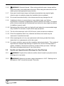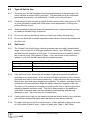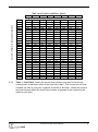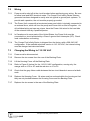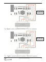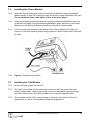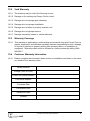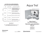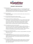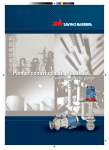
1
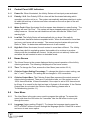
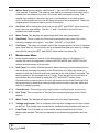
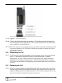
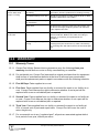
Infinity Series Saltwater Chlorine Generator
Installation and Operation Manual
Compu Pool Infinity Series Manual
1
Infinity Series Saltwater Chlorine Generator
Installation and Operation Manual
1.0
INTRODUCTION ................................................................................................. 3
2.0
GETTING STARTED ........................................................................................... 3
3.0
SAFETY INFORMATION ..................................................................................... 3
4.0
THE CHEMISTRY INVOLVED ............................................................................ 5
5.0
WATER CHEMISTRY.......................................................................................... 5
6.0
ADDING SALT TO POOL OR SPA...................................................................... 7
7.0
INSTALLATION ................................................................................................. 10
8.0
INSTALLATION CHECKLIST ............................................................................ 15
9.0
OPERATION ..................................................................................................... 16
10.0 MAINTENANCE ................................................................................................ 20
11.0 TROUBLESHOOTING....................................................................................... 22
12.0 WARRANTY ...................................................................................................... 24
Compu Pool Infinity Series Manual
2
1.0 INTRODUCTION
1.1.1
Congratulations on your recent purchase of a Compu Pool Products Infinity Series
Saltwater Chlorine Generator. Please take a moment to read through the entire
manual before installing your new unit. Your generator must be installed and
operated as specified.
2.0 GETTING STARTED
2.1.1
READ THIS FIRST. As with any electrical device it is very important that the
installation and service of this equipment be performed by a qualified person with
the skills and experience required to do it safely and correctly. Improper installation
or service can result in severe electrical shock to the installer or user of the
equipment or pool. Please choose your installer with great care.
3.0 SAFETY INFORMATION
3.1
IMPORTANT SAFETY INSTRUCTIONS, READ AND FOLLOW ALL
INSTRUCTIONS. SAVE ALL INSTRUCTIONS.
3.1.1
iWARNING: To reduce the risk of injury, do not permit children to operate this
device.
3.1.2
iWARNING: To reduce the risk of electric shock, fire or injury, service of this
device should only be attempted by a qualified professional.
3.1.3
iWARNING: Ensure electrical power is disconnected before wiring the unit.
Follow all state / local / NEC (CEC if applicable) electrical codes. Use copper
conductors only.
3.1.4
iWARNING: Factory wired for 208-240 VAC service. If available electrical
service is 110-120 VAC, the power supply wiring must be changed as shown in
section 7.3.
3.1.5
iWARNING: One bonding lug is provided on the external surface of the Infinity
Series Chlorine Generator. To reduce the risk of electric shock, connect the local
common bonding grid in the area of the swimming pool, spa, or hot tub to this
terminal with a copper conductor not smaller than 8 AWG US / 6 AWG Canada.
Compu Pool Infinity Series Manual
3
3.1.6
iWARNING: Chemical Hazard - When mixing acid with water, always add the
acid to the water, never add water to the acid. When using the acid ensure to use
rubber gloves and appropriate eye protection.
3.1.7
Heavy pool (and/or spa) usage, and higher temperatures may require higher
chlorine output to maintain proper free available chlorine residuals.
3.1.8
Do not add chemicals directly to the skimmer as this may damage the cell.
3.1.9
If additional chlorine is required due to heavy bather loads, use Sodium
Hypochlorite to maintain an appropriate chlorine residual in the water. For outdoor
pools, chlorine residuals can be protected from destruction by sunlight by addition
of stabilizer (cyanuric acid).
3.1.10 Maintaining high chlorine and very high salt levels above the recommended range
may contribute to corrosion of pool (and/or spa) equipment.
3.1.11 The life of the electrolytic cell is 12,500 hours, under normal use conditions.
3.1.12 Check the expiration date of any chemical test kits as test results may be
inaccurate if used after that date.
3.1.13 When replacing the cell, only use replacement cells having a label that clearly
states that it is a replacement cell for this model.
3.1.14 For proper sanitation, spas must be completely drained periodically. The number of
days between complete spa drainage is equal to the volume of the spa water in
gallons, divided by 10 times the maximum number of daily spa users. Refill spa
with water and repeat directions of use of this device.
3.2
Health and Hyperthermia Warnings for Spa Devices
3.2.1
iWARNING: People with a medical condition should consult a physician before
entering pool or spa water.
3.2.2
iWARNING: Maximum spa water usage temperature is 104°F.
Bathing time in
spa water at 104°F should not exceed 15 minutes.
Compu Pool Infinity Series Manual
4
4.0 THE CHEMISTRY INVOLVED
4.1.1
The Infinity Series chlorine generator by electrolysis creates chlorine to sanitize
your pool using the salt molecules (NaCL) in your water. A small electric charge is
applied across a set of titanium plates inside the Electrolytic Cell. This produces
Sodium Hypochlorite (NaOCl). In water, Sodium Hypochlorite dissociates into
sodium (NA+) and hypochlorite (OCl-) ions.
4.1.2
It is the hypochlorite ions that form with the hydrogen (H+) ions (from the water) to
form hypochlorous acid (HOCl), which is the active agent that destroys bacteria and
algae, and oxidizes organic matter. This form of chlorine works quickly in the pipe,
leaving only a mild residual in the pool.
5.0 WATER CHEMISTRY
5.1
WARNING: Prior to turning on your Infinity Series Chlorine
Generator for the first time (including reopening your pool for the
new pool season) your water chemistry must be balanced
according to the following guidelines.
5.2
Recommended Salt and Pool / Spa Chemistry Readings
Free Available Chlorine
pH
Total Alkalinity
Calcium Hardness
Stabilizer (Cyanuric Acid)
Total Dissolved Solids
Salinity
Swimming Pools
1.0 – 3.0 ppm
7.2 – 7.8
100 – 120 ppm
200 – 300 ppm
30 – 60 ppm
< 1,200 ppm
3000 – 4000ppm
Spas
3.0 – 5.0 ppm
7.2 – 7.8
100 – 120 ppm
150 – 200 ppm
30 – 60 ppm
< 1,200 ppm
3000 – 4000ppm
5.2.1
Chlorine Stabilizer (Cyanuric Acid). Chlorine Stabilizer is needed to maintain
proper levels of chlorine. Unstable chlorine can be destroyed by the sun’s UV
radiation within two hours. Chlorine stabilizer must be maintained between 30 – 60
ppm.
5.2.2
Nitrates and Phosphates. These chemicals can cause extremely high chlorine
demands and will deplete chlorine from your pool. In some cases, they may even
lower your chlorine levels to zero. Your local pool professional can test for Nitrates
and Phosphates and recommend methods of removal.
5.2.3
Metals. Metals can cause loss of chlorine. Also, metals can stain your pool and tint
your water. Have your local pool professional check for metals and recommend
methods of removal.
Compu Pool Infinity Series Manual
5
5.2.4
Chloramines. Chloramines should not be present in pool water. When organic
materials are not fully oxidized by Free Chlorine, Chloramines are formed. This ties
up the Free Chlorine in your pool, and does not allow the chlorine in your pool to
disinfect. Chloramines also cloud pool water and burn the eyes. Shock the pool
with chlorine to remove Chloramines at the initial start up of the pool.
5.2.5
pH Levels. pH produced by a chlorine generator is close to neutral pH. However,
other factors usually cause the pH of the pool water to rise. Therefore, the pH in a
pool chlorinated by a chlorine generator tends to stabilize at approximately 7.8.
This is within national standards. If the pool pH rises above 7.8, have a pool
professional test to see if other factors such as high Calcium Hardness or Total
Alkalinity are the cause, and then balance accordingly.
5.2.6
Total Dissolved Solids (TDS). Adding salt to pool water will raise the TDS level.
While this does not adversely affect the pool water chemistry or clarity, the pool
water professional testing for TDS must be made aware that salt has been added
for a chlorine generator system. The individual performing the TDS test will then
subtract the salinity level to arrive at the correct TDS level.
5.3
Water Chemistry Helpful Hints
5.3.1
Proper operation of the chlorine generator can be easily verified by inspecting the
Electrolytic Cell. The chlorine being produced will appear as a fog at one end of the
plates.
5.3.2
If the pool remains cloudy, or the chlorine residual tests low, then the chlorine being
produced is being lost due to high chlorine demand or improper water conditions.
Take a water sample to a pool professional to ensure that the pool water is
balanced correctly.
5.4
Recommended List
5.4.1
Read and keep your manual in a safe place.
5.4.2
Increase chlorine production when temperature goes up.
5.4.3
Increase chlorine production when number of guests go up.
5.4.4
Use Stabilizer (Cyanuric Acid) to protect free chlorine in pool
5.4.5
Decrease chlorine production when temperature goes down.
5.4.6
Take pool water sample to a Pool Professional once per month.
5.5
Not Recommended List
5.5.1
Do not allow fertilizer anywhere near your pool. Fertilizers contain Nitrates or
Phosphates which cause severe chlorine demand in pool water.
5.5.2
Never use dry acid to adjust pH. A build up of by-products can damage the
Electrolytic Cell.
Compu Pool Infinity Series Manual
6
5.5.3
Do not add any pool water balancing chemicals (including salt) unless the Power
Unit is turned off.
5.5.4
Do not add any chemicals (including salt) to the skimmers.
5.5.5
Do not let salinity level drop below 3000 ppm.
5.6
Definitions
5.6.1
Algae. Plant-like organisms which grow in water. Especially active in summer
conditions, where chlorine disinfectant level is too low to destroy them. Algae may
be green, yellow, brown or black (Black Spot) in color.
5.6.2
Chlorine Demand. The amount of chlorine that should be added to the water to
provide proper bacteria and algae control.
5.6.3
Chlorine Residual. The amount of chlorine left over, after the “demand” has been
met.
5.6.4
Combined Chlorine. Weak chlorine which is combined with the contaminants in
the water.
5.6.5
Free Chlorine. Active chlorine in the water with the potency to destroy
contaminants.
5.6.6
Shock Treatment. The removal by means of oxidation of those materials that have
chlorine demand.
6.0 ADDING SALT TO POOL OR SPA
6.1
Adding Salt
6.1.1
DO NOT add pool/spa chemicals directly to the skimmer. This may damage the
cell. Maintaining high salt levels above the recommended range can contribute to
corrosion of pool/spa equipment. If the chlorine generator has already been
installed, it must be turned off before adding salt. The recommended salt
concentration for the Infinity Series is 3500 ppm.
6.1.2
For pools it is best to empty the required salt into the shallow end of the pool and
run the filter and pump simultaneously while the Infinity Series chlorine generator is
off to circulate the water and dissolve the salt. Do not throw the salt bag into the
pool or spa as chemicals and inks on the bag can interfere with the water balance.
6.1.3
Salt may take 24 – 48 hours to dissolve in the summer and longer in the winter.
Finer granules of salt will dissolve faster than compressed pellets.
Compu Pool Infinity Series Manual
7
6.2
Type of Salt to Use
6.2.1
The more pure the salt the better the life and performance of the electrolytic cell.
Use a salt that is at least 99.8% pure NaCl. The preferred salt is an evaporated,
granulated, food quality, non-iodized salt. Consult your local pool store.
6.2.2
Avoid using salt with anti-caking agents (sodium ferrocyanide, also known as YPS
or yellow prussiate of soda) that could cause some discoloration of fittings and
surface finishes in pool.
6.2.3
Water conditioning salt pellets are compressed forms of evaporated salt and may
be used but will take longer to dissolve.
6.2.4
Do not use calcium chloride as a source of salt (use sodium chloride only).
6.2.5
Do not use Rock salt. Insoluble impurities mixed with the rock salt can shorten the
life of the unit.
6.3
Salt Level
6.3.1
The Compu Pool Infinity Series chlorine generator can work with a broad salinity
range, from a minimum of 3000 ppm (parts per million), up to 8000 ppm. However,
the ideal level for operation is 3500 ppm. To achieve this level of salinity, add 30
lbs. of salt for every 1000 gallons of water. If you are unsure of the number of
gallons in your pool, double-check with the equations below.
Rectangular
Round
Oval
Gallons (Measurements in Feet)
Length x Width x Average Depth x 7.5
Diameter x Diameter x Average Depth x 5.9
Length x Width x Average Depth x 6.7
6.3.2
If the salt level is low, determine the number of gallons in the pool and add salt
according to the chart below. A low salt level will reduce efficiency of the chlorine
generator and result in low chlorine production. A high salt level can cause a salty
taste to your pool and may damage pool equipment. In addition, operating the unit
outside the recommended salt range will rapidly reduce the longevity of the cell.
The salt in your pool/spa is constantly recycled and the loss of salt throughout the
swimming season should be small. This loss is due primarily to the addition of
extra water to replace water lost from splashing, backwashing, and draining
(because of rain). Salt is not lost due to evaporation.
6.3.3
If salt content is too high you will need to reduce the level of water in your pool/spa
and refill the pool/spa with fresh water that has not been diluted with salt.
6.3.4
To initially start a pool with the correct amount of salt, add salt to the pool at a rate
of 0.03 pounds of salt for every 1 gallon of water (see Table 1: Salt Table).
Compu Pool Infinity Series Manual
8
Salt Level before addition (ppm)
0
500
1000
1500
2000
2500
3000
3500
17
25
33
42
50
58
67
75
83
92
100
108
117
125
133
142
150
158
167
175
183
192
200
209
217
225
234
242
251
0
0
0
0
0
0
0
0
0
0
0
0
0
0
0
0
0
0
0
0
0
0
0
0
0
0
0
0
0
Volume of Water in thousands of gallons
How Much Salt to Add in pounds
6.3.5
4
6
8
10
12
14
16
18
20
22
24
26
28
30
32
34
36
38
40
42
44
46
48
50
52
54
56
58
60
117
175
234
292
350
409
467
525
584
642
701
759
817
876
934
992
1051
1109
1168
1226
1284
1343
1401
1460
1518
1576
1635
1693
1752
100
150
200
250
300
350
400
450
500
550
600
651
701
751
801
851
901
951
1001
1051
1101
1151
1201
1251
1301
1351
1401
1451
1501
83
125
167
209
250
292
334
375
417
459
500
542
584
626
667
709
751
792
834
876
917
959
1001
1043
1085
1126
1168
1210
1252
67
100
133
167
200
234
267
300
334
367
400
434
467
500
534
567
600
634
667
701
734
767
801
834
867
901
934
968
1001
50
75
100
125
150
175
200
225
250
275
300
325
350
375
400
425
450
475
500
525
550
575
600
626
651
676
701
726
751
33
50
67
83
100
117
133
150
167
183
200
217
234
250
267
284
300
317
334
350
367
384
400
417
434
450
467
483
500
Table 1 - Salt Table. Locate the column that contains your pool’s current salt
concentration in parts per million at the top of the chart. Then locate the row that
contains the size of your pool in gallons at the left of the chart. Where the column
and row intersect within the chart is the number of pounds of salt required to be
added to your pool.
Compu Pool Infinity Series Manual
9
7.0 INSTALLATION
7.1
Overview
7.1.1
The Power Module is to be mounted at least 3 feet above ground level, and if
possible protected from direct weather. The Cell Module is to be plumbed into the
return line to the pool after the pump and filter and heater, if applicable (see Figure
1). The Cell Module has a 15 feet cable to connect to the Power Module. The
Power Module must be installed 10 feet or more away from the pool edge.
7.1.2
Figure 1 - Installation Schematic.
Compu Pool Infinity Series Manual
10
7.2
Wiring
7.2.1
Power must be shut off at the circuit breaker before performing any wiring. Be sure
to follow local and NEC electrical codes. The Compu Pool Infinity Series chlorine
generator has been designed to easily wire into typical in-ground pool systems. To
provide safe operation, the unit must be properly grounded.
7.2.2
The Power Unit comes with a terminated power cord which is typically connected to
an external timer, which will turn the pump and Power Unit on and off together. As
all individual wiring set ups are unique, have the Power Unit wired to the load side
of the external timer by a qualified person.
7.2.3
In Canada and in some parts of the United States, the Power Unit must be
connected to a circuit protected by a Class A ground fault interrupter (GFI). Check
local codes before connecting.
7.2.4
The Compu Pool Infinity Series is shipped from the factory with a 208-240 VAC
configuration. If the available electrical service is 110-120 VAC, the internal wiring
must be changed as instructed below.
7.3
Changing the Wiring to 110-120 VAC
7.3.1
Power must be disconnected.
7.3.2
Remove the six screws from the rear of the Backing Plate.
7.3.3
Lift the Housing Cover off the Backing Plate.
7.3.4
Refer to Figure 2 (below) for the 110-120 VAC configuration, moving only the
orange wire on J12 to J10 and the red wire on J7 to J6.
7.3.5
Check that the gray ribbon cable between the two circuit boards is secured at both
ends.
7.3.6
Replace the Housing Cover. All wires must be enclosed within the housing so that
they are not pinched between the Housing Cover and the Backing Plate.
7.3.7
Replace the six screws in the rear of the Backing Plate.
Compu Pool Infinity Series Manual
11
110-120 VAC
Connections
7.3.8 Figure 2 - Internal Transformer Connections, 110-120 VAC Connections.
208-240 VAC
Connections
7.3.9
Figure 3 - Internal Transformer Connections, 208-240VAC Connections.
Compu Pool Infinity Series Manual
12
7.4
Installing the Power Module
7.4.1
Mount the Power Module as close to the pump and filtration system as possible.
Make sure the 15 feet Cell Cable can reach the section of pipe selected for the cell.
Do not install the Power Unit within 10 feet of the pool edges.
7.4.2
Using the provided screws and anchors, secure the Mounting Bracket at eye level
to the wall or support. Once the Mounting Bracket is tightly secured, lift the Power
Module onto the Mounting Bracket and secure with the provided screws.
7.4.3
A lug for bonding is attached to the bottom of the Power Module (see Figure 4).
Connect to the pool bonding system using minimum 8 AWG copper wire if required
by code.
7.4.4
Figure 4 - Bonding Lug Position.
7.5
Installing the Cell Module
7.5.1
Be sure the pool pump is turned off.
7.5.2
The Cell is to be fitted into the return line to the pool after the pump, filter and
heater (if applicable). Water flow should come from the filtration system through
the inlet closest to the Cell Cable and back out through the opposite outlet.
7.5.3
The orientation of the Cell in the plumbing is critical for the function of the unit.
Please refer to Figure 5 for available plumbing configurations.
Compu Pool Infinity Series Manual
13
The Infinity Cell can be installed in
any manner as long as the top side
of the housing is facing upwards as
shown in all of the plumbing
scenarios below:
7.5.4
The Infinity Cell cannot be installed
vertically, except in the plumbing
installation shown below with the
cable to the top (contains water
sensor) and with a gas trap created
immediately above the cell. This
installation is not recommended and
should only be implemented when
there is no other option.
Figure 5 - Cell Installation Options.
Compu Pool Infinity Series Manual
14
7.5.5
Make sure that the 15 foot Cell Cable reaches from the Power Module to the area
where you will be installing the Cell.
7.5.6
The Cell Module comes with Unions to connect to the filtration plumbing. These
Unions enable the Cell to be easily removed for cleaning etc. The Unions are sized
to take 2" pipe, if a 1½" pipe connection is required, reducers will need to be fitted.
7.5.7
To install the Unions cut out a 14" section of pipe out of the desired installation
location. Use plumbing Cleaner Primer to clean and prepare the pipe ends and
Union Sockets. Place the Union Collars over the pipe ends. Using plumbing Solvent
Cement glue the Union Sockets to the pipe ends.
7.5.8
Ensure that the o-rings are fitted to the Union Sockets and apply a suitable o-ring
lubricant if required. Place the Cell Housing between the Unions and tighten the
Collars onto the Housing. Do not over tighten the Collars and only tighten them by
hand.
7.5.9
Connect the Cell Cable to the Power Module. Place the Cable Connector against
the Power Module receptacle. Turn slowly until the bayonet keyway is found, push
in and then turn the locking collar clockwise firmly to secure.
8.0 INSTALLATION CHECKLIST
8.1.1
Cell Unions installed and glued into pipe work.
8.1.2
Union Collars firmly connected into the Cell Housing.
8.1.3
The metal Mounting Bracket is securely affixed to a wall or support.
8.1.4
The Power Module is mounted and secured in place onto the Mounting Bracket.
8.1.5
The Power Module is wired to the correct power source.
8.1.6
The Cell Cable is securely connected to the Power Module.
8.1.7
Sufficient salt has previously been added and fully dissolved into pool water.
8.1.8
You have checked and confirmed that the Power Module switches ON and OFF
with the filter pump.
8.1.9
You have checked all connections and joints for leaks.
Compu Pool Infinity Series Manual
15
9.0 OPERATION
1
7
8
2
8
7
3
4
5
6
9.1.1
Figure 6 - Keypad Controls
9.2
Start Up Procedure
9.2.1
Upon the initial start up of the Infinity unit, the Cell size will need to be selected.
When first powered on the display screen will read "SELECT CELL", use the LEFT
and RIGHT buttons to change the selection, use the OK button to confirm the
selection. The unit will then return to the home screen.
9.2.2
If you do not know what size Cell you have, refer to the serial label sticker on the
top of the Cell Housing which will state either i15, i25, i40 or i60.
9.2.3
Note: Each time the unit is powered on, the display will perform a 1 minute self-test,
and then return to the Home Screen.
Compu Pool Infinity Series Manual
16
9.3
Control Panel Buttons
9.3.1
1. On / Off. For normal operation, the system should be left in the “On” state. In this
state the Infinity Unit will produce chlorine according to the desired output %.
Simply press the button again to turn the unit off.
9.3.2
2. OK Button. Holding this button in for 3 seconds will open the User Menu (see
section 9.5). This button is also used to select settings, and cycle through menus.
9.3.3
3. Manual Override. This button allows you a manual override to control the
system without having to change the unit's settings. When you have finished with
the manual override simply re-press the button to de-activate and return your unit to
its normal settings.
9.3.4
4. Salinity Test. Pressing this button will display the most recent salinity test result
(automatically conducted every hour). One of the following readings will be given:
"Low Salt" - The salinity level is low and salt needs to be added to the pool water.
"Salt OK" - No action is required. "High Salt" - No action is required, the Infinity can
run with high salinity, however very high salinity may be unpleasant to swim in and
may damage other equipment. To perform a real time salinity test, press the LEFT
and RIGHT buttons simultaneously for 3 seconds.
9.3.5
5. Super Chlor. When you have an abnormally high bather load, a large amount of
rain, a cloudy water condition which needs a large amount of purification to be
introduced, simply press the SUPER CHLOR button. This electronically “super
chlorinates” the water for 24 hours of physical run time. If the unit is turned off by
pressing the On/Off button or if the SUPER CHLOR button is pressed again, the
unit will return to normal operation.
9.3.6
6. Winter Mode. When you are not using your pool during the winter months, it is
advisable to activate the winter mode. Simply press the WINTER MODE button.
The Winter Mode will reduce the output of chlorine to 50% of the set chlorine
output. For example: If chlorine output is set to 80%, it will change to 40% when the
WINTER MODE button is pressed. To deactivate winter mode, simply press the
button again. Note: Reducing the chlorine output during periods when the pool is
not in use will help maximize the life of the cell.
9.3.7
7. Output. Pressing the "+" or "-" buttons will change the chlorine production output
in 10% increments. Note: When initially starting up your Infinity chlorine generator it
is recommended that the output be set at 100%, decreasing in 10% increments
ensuring that the unit is maintaining the appropriate chlorine level in your pool/spa.
9.3.8
8. Left and Right Arrows. Pressing the LEFT or RIGHT arrow will enable
navigation through the menu options.
Compu Pool Infinity Series Manual
17
9.4
Control Panel LED Indicators
9.4.1
Power On. When illuminated, the Infinity Series unit has input power activated.
9.4.2
Polarity 1 & 2. One Polarity LED at a time will be illuminated indicating which
operation cycle the unit is on. The system automatically switches polarities in order
to inhibit the build up of calcium and other minerals on the cell as part of the selfcleaning feature.
9.4.3
Water Fault. When illuminated, the flow sensor has detected no water flowing. The
display will read “No Flow”. The system will have stopped producing chlorine as a
safety measure. Severe low salt conditions will also activate the “Water Fault”
warning light.
9.4.4
Low Salt. The Infinity Series will automatically let you know if the salinity
concentration has fallen below acceptable levels. When illuminated for more than
two hours, add more salt as needed. The amount required varies with pool size.
Refer to Table 1 to determine additional amount of salt needed.
9.4.5
High Salt. When illuminated, the salt content is more than sufficient. The Infinity
Series has a built-in regulating system that enables it to continue to produce
chlorine with the increased salt content. At this point do not add any further salt
and allow the salt content to return to desirable levels.
9.5
Home Screen
9.5.1
The Home Screen is the screen displayed during normal operation of the Infinity
chlorine generator. The following is displayed on the home screen:
9.5.2
Time: To change the Time, access the User Menu (see section 9.6.4).
9.5.3
Chlorine Output Setting Percentage: To change the chlorine output setting, use
the "+" and "-" buttons. The setting will be changed in 10% increments.
9.5.4
Chlorine Output Bars: The Chlorine Output Bars represent the actual amount of
chlorine being produced. There are 10 production bars, so if the output is set to
100% there should be 10 bars illuminated, if the output is set to 60% there should
be 6 bars. It is normal for the last two bars to fluctuate in illumination. If the Chorine
Output Bars do not match the Chlorine Output Setting, please refer to
Troubleshooting (section 11).
9.6
User Menu
9.6.1
The User Menu is the main menu used to program the settings. To access this
menu hold down the OK button for 3 seconds. Use the OK button to also cycle
through the menu.
9.6.2
Language (factory setting “English”): To change the language simply press the
LEFT or RIGHT buttons to scroll through the language options. Press OK to select
and move to next menu option.
Compu Pool Infinity Series Manual
18
9.6.3
Which Timer (factory setting “Use External”): Use the LEFT button to change to
“Use Internal” if required. The external timer setting is used when the Infinity unit is
hardwired to an external time clock, this usually also operates the pump. The
Internal time setting is used when the unit is not hardwired to an external time
clock, in this scenario the On and Off times will need to be programmed. These are
programmed in the same manner as Set Clock below.
9.6.4
Set Clock: When setting the clock time use the LEFT and RIGHT arrow buttons to
select the hour and minutes. Use the "+" and "-" buttons to move the cursor
between hour and minutes.
9.6.5
Water Temp: This displays an approximate real time water temperature.
9.6.6
Salt Result: This is a read out of the most recent salinity test result. One of the
following readings will be given: "Low Salt", "Salt OK" or "High Salt".
9.6.7
Cell Select: This does not normally need to be changed as the Cell size is selected
upon initial start up. If the incorrect cell is accidently selected upon start up, change
the selection using the LEFT and RIGHT buttons and then press OK.
9.7
Maintenance Menu
9.7.1
Under normal operation, access to the Maintenance Menu is not required. To
access the menu for diagnostics, hold the WINTER MODE and SUPER CHLOR
buttons simultaneously for 3 seconds.
9.7.2
Self Clean: The Infinity chlorine generator has an automatic Cell cleaning function
that works by reversing the polarity of the Electrolytic Cell. When the polarity is
reversed, build up of calcium and other minerals on the Cell plates is removed. The
factory setting for the reversing time is 6 hours. There are also 4 hour and 8 hour
options that can be selected by using the LEFT and RIGHT buttons. Note:
Decreasing the reversing time to 4 hours will reduce the life of the Electrolytic Cell,
this should only be done when there are high calcium levels in the pool water and
the Cell is calcifying quickly.
9.7.3
Cover Sensor: This setting is only required when configuring with a pool cover.
9.7.4
Unit Temp: This is a read out of the real time internal temperature of the Power
Module.
9.7.5
Water Temp: This displays an approximate real time water temperature.
9.7.6
Voltage and Current: This is a display of the real time Voltage and Current outputs
to the Cell. This display may be required for troubleshooting problems with the unit.
9.7.7
Peak Temp: This is a read out of the hottest internal temperature the Power
Module has reached. This may be required for troubleshooting problems with the
unit.
Compu Pool Infinity Series Manual
19
10.0 MAINTENANCE
10.1
Water Chemistry
10.1.1 It is recommended that a pool water sample be taken to a Pool Professional once
per month for analysis. Please refer to Water Chemistry (section 5.0) for additional
information.
10.2
Electrolytic Cell
10.2.1 The cell operates most efficiently when it is clean. As a natural result of the
electrolytic process which creates chlorine from salt molecules, calcium is attracted
to the titanium plates in the cell. The self-cleaning feature helps to inhibit such build
up and scaling. However, the attraction of calcium and other minerals is inevitable
and eventually it must be removed. The cell only needs cleaning to ensure that
build up does not cause individual plates to come in contact with each other.
10.2.2 The clear housing of the cell allows easy visual inspections, and with correct water
chemistry, the cell will only need cleaning approximately every 3-6 months. In
regions with hard water (high calcium levels), more frequent cleaning may be
required.
10.3
Cleaning the Cell
10.3.1 Turn power to the filter pump and Power Module off.
10.3.2 Remove the cell from its position in the plumbing by loosening the Union Collars on
both ends of the Cell. Unplug the Cell Cable from the Power Module if required.
10.3.3 With the Cell removed use a high pressure hose nozzle to spray off as much loose
scale and debris as possible.
10.3.4 Do not use any sharp or metallic objects to remove scale. Scraping or scratching
the cell plate's edge or surface will allow chemical attack of the plate, cause
premature failure of the cell and will void the warranty.
10.3.5 If further cleaning is required the cell needs to be cleaned in a mixture of one (1)
part Hydrochloric (Muriatic) Acid into four (4) parts water.
10.3.6
iWARNING: Chemical Hazard - When mixing acid with water, always add the
acid to the water, never add water to the acid. When using the acid ensure to use
rubber gloves and appropriate eye protection.
10.3.7 Connect the Cell Cleaning Plug to the end of the Cell Housing opposite the cable
using the Cell Cleaning Collar (see Figure 7). Place the Cell upright on a stable flat
surface with the Plug facing down.
Compu Pool Infinity Series Manual
20
10.3.8 Figure7 - Cell Cleaning Plug
10.3.9 Fill the Cell with the acid cleaning solution (1-2" from the top port) and clean until
the foaming action stops (typically 5 to 10 minutes). Rinse the cell with fresh water
and re-install into the plumbing line.
10.3.10 Note: Do not leave the cleaning solution in the Cell for more than 15 minutes as this
may cause damage to the Cell plates. Additionally excessive cleaning will reduce
the lifespan of the cell.
10.4
Winterizing the Cell
10.4.1 The Electrolytic Cell will be damaged by freezing water just as your pool plumbing
would. In areas which experience severe or extended periods of freezing
temperatures, be sure to drain all water from the pump, filter, supply and return
lines before any freezing conditions occur. Remove the Cell and store it indoors.
The Power Unit is capable of withstanding winter weather and does not need to be
removed.
10.5
Replacing the Cell
10.5.1 When the titanium blades inside the Electrolytic Cell have reached the end of their
lifespan, replacements are available so that the whole system does not have to be
replaced. Replacements are easily switched out. To ensure quality and value, only
genuine Compu Pool replacement parts may be used.
Compu Pool Infinity Series Manual
21
10.5.2 To remove the cell for replacement turn power to the filter pump and Power Module
off. Disconnect the Cell Cable from the Power Module by turning the locking collar
anti-clockwise. Loosen the two Cell Union Collars and remove the cell.
10.5.3 Replace with the new cell in the opposite manner. There are no changes that need
to be made to the Power Module control settings when replacing the Cell.
11.0 TROUBLESHOOTING
Problem
Possible Cause
Power LED and
Display Screen not
turning on.
Power not connected to unit. Check that the Power Module is connected to a 208240 VAC service, or a 110-120 VAC service. Check
that the Power Module internal wiring matches the
voltage (see section 7.3)
Low or no chlorine
residual.
Corrective Action
Circuit Breaker Tripped.
Verify input voltage with a voltmeter. If there is input
power, the circuit breaker may have tripped. The
Infinity Series is protected by a 3 amp circuit breaker
located at the base of the Power Module. To reset the
circuit breaker press the small yellow pin back in. Main
power to the unit must be turned off prior to resetting
the circuit breaker. Should the circuit breaker continue
to trip after this exercise then you should consult
Compu Pool for assistance.
Loose ribbon cable between
Power Circuit Board and
Display Circuit Board.
Check that the ribbon cable between the Power Circuit
Board (back) and the Display Circuit Board (front) is
securely connected.
Insufficient chlorine output %. Increase chlorine production by pressing the "+"
button.
Insufficient running times.
Increase the operating hours of the pool filtration
pump and chlorine generator.
Low stabilizer (cyanuric acid) Add stabilizer to maintain a level of 30 – 60 ppm.
level in pool water.
Ph too high.
Adjust Ph level to 7.2 – 7.8.
Temporary loss of chlorine
due to heavy bather load,
rain, organic matter.
Set the unit to Super Chlor and let run for a 24 hour
period. Re-check and if still low take pool water
sample to pool professional.
Salt Content below 2500ppm Add additional salt to pool to bring salinity within 3000
- 4000ppm (3500 ideal), see Table 1.
Calcified or clogged cell.
Remove cell from plumbing line and clean (see section
10.3).
High nitrates or phosphates
in pool water.
Contact pool professional.
Metals present in pool water. Contact pool professional.
Compu Pool Infinity Series Manual
22
Water Fault LED on.
Insufficient or no water flow
through cell.
Check that the pump is operating correctly and turns
on and off with the chlorine generator with the timer.
Ensure that pump strainer baskets are not clogged.
Check that all valves are opened correctly. Check for
any blockages.
Clean or backwash filter if dirty.
Low Salt LED on.
Pump speed too low (for
multi speed pumps)
Increase the pump speed to ensure consistent and
sufficient water flow through the Cell.
No salt in pool water.
Add salt to pool water to reach required level of 30004000ppm (3500 ideal), see Table 1.
Cell Cable not connected to
Power Module.
Check that the Cell Cable connector is correctly fitted
to the Power Module receptacle and the locking collar
is tightened firmly.
Damaged Cell Cable.
Check that the Cell Cable has not been damaged.
Very cold pool water.
If the pool water is below 45° Fahrenheit, chlorine
production will cease and the Water Fault LED will turn
on. The pool should be winterized (see section 10.4)
Not enough salt added upon
start up of pool.
Add salt to pool water to reach required level of 30004000ppm (3500 ideal), see Table 1.
Salinity level decreased over Add salt to pool water to reach required level of 3000time due to splashing,
4000ppm (3500 ideal), see Table 1.
backwashing, rainfall etc.
Excessive calcium build up
on Cell Plates.
Clean Cell as instructed in section 10.3.
Cold pool water.
Pool water is below 60°F. No action is required,
chlorine production is working correctly.
Dying Cell.
The Electrolytic Cell has come to the end of the "cell
life" and is no longer producing chlorine at sufficient
levels. Replace the Cell.
High Salt LED on.
Too much salt has been
added to the pool.
The salt content is more than sufficient. The Infinity
Series has a built-in regulating system that enables it
to continue to produce chlorine with the increased salt
content. No action is required, however very high
salinity may be unpleasant to swim in and may
damage other equipment. Backwash or partially drain
pool and add fresh water to reduce the salinity level.
Low Salt LED or High
Salt LED on upon
startup when known
salt level is correct.
Incorrect Cell selected in
User Menu
Access the User Menu and select the correct cell, see
section 9.6.7.
"NO CELL" reading on The Cell Cable is not
display screen.
correctly connected to the
Power Module
Ensure the Cell Cable is correctly fitted, refer to
section 7.5.9.
Compu Pool Infinity Series Manual
23
Output bars on display Last two output bars
It is normal for the last two bars to fluctuate in
screen lower than
fluctuating.
illumination. Chlorine production is working correctly.
output % setting.
Pool water salinity is too low. Add salt to pool water to reach required level of 30004000ppm (3500 ideal), see Table 1.
Frequent calcification
of the Cell.
Excessive calcium build up
on Cell Plates.
Clean Cell as instructed in section 10.3.
Dying Cell.
The Electrolytic Cell has come to the end of the "cell
life" and is no longer producing chlorine at sufficient
levels. Replace the Cell.
Imbalanced water.
The water may contain high pH, total alkalinity and
calcium hardness. Balance the water according to
section 5.2. Contact a pool professional for
assistance.
Self cleaning reversing time
to long.
Access the Maintenance Menu to reduce the cell
reversing time (see section 9.6.2). Note: Decreasing
the reversing time will reduce the life of the Electrolytic
Cell.
12.0 WARRANTY
12.1
Warranty Terms
12.1.1 Compu Pool Infinity Series chlorine generators carry the following three year
warranty should fault occur due to faulty manufacturing or materials.
12.1.2 For residential use, Compu Pool warrants the original purchaser that the equipment
shall be free of manufacturer defects at the time of sale and upon examination,
shall provide replacement parts or repair in accordance with the following schedule:
12.1.3 First 60 Days. Parts supplied at no cost.
12.1.4 First Year. Parts supplied from our facility or returned for repair to our facility at no
cost. Compu Pool reserves the right to determine whether or not a part will be
replaced with a new or refurbished part or repaired.
12.1.5 Second Year. Parts supplied from our facility or returned for repair to our facility at
no cost. Compu Pool reserves the right to determine whether or not a part will be
replaced with a new or refurbished part or repaired.
12.1.6 Third Year. Parts supplied from our facility or returned for repair to our facility at
66% of normal cost of parts and repair labor. Compu Pool will cover the cost of
return freight only.
12.1.7 For commercial use in any “regulated pool”, all parts are warranted against defect
for a period of one year, without pro-ration.
Compu Pool Infinity Series Manual
24
12.2
Void Warranty
12.2.1 The warranty may be void if the following occurs:
12.2.2 Damage to the unit beyond Compu Pool's control.
12.2.3 Damage due to improper pool chemistry.
12.2.4 Damage due to improper installation.
12.2.5 Damage due to failure to properly maintain unit.
12.2.6 Damage due to improper service.
12.2.7 Damage caused by insects or natural elements.
12.3
Warranty Coverage
12.3.1 This warranty is applicable to workmanship and materials only and Compu Pool, its
agents, employees, and affiliates expressly disclaim responsibility for loss, damage,
or injuries to persons or property arising from warranty failure, or installation of
equipment. Warranty claims must be initiated in a timely manner by calling (888)
989-SALT.
12.4
Customer Warranty Information
12.4.1 Please complete the information below at time of installation and retain in the event
you need to file a warranty claim
Model Number
Voltage (240v or 120v)
Power Unit Serial Number
Cell Serial Number
Purchase Date
Purchased From
Installation Date
Installer
Compu Pool Infinity Series Manual
25