1
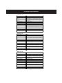
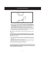
CLEARWATER
SALT CHLORINATOR LM2 SERIES
®
PROFESSIONAL INSTALLATION MANUAL,
OWNER’S MANUAL AND WARRANTY INFORMATION
CLEARWATER SALT CHLORINATOR
CHLORINE GENERATING DEVICE
LM2 SERIES FOR RESIDENTIAL POOLS
DOMESTIC
REGISTRATION NUMBER:
MODEL LM2-15: 27850
MODEL LM2-24: 27580
MODEL LM2-40: 27851
PEST CONTROL PRODUCTS ACT
READ THE LABEL, INSTALLATION AND OWNER’S MANUALS BEFORE USING.
PLEASE KEEP YOUR OWNER’S MANUAL AS IT CONTAINS YOUR WARRANTY.
THE CLEARWATER SALT CHLORINATOR CONTAINS A POWER PACK AND A CELL.
Controls Bacteria and Algae in Swimming Pool Waters.
Maximum output of hypochlorous acid equivalent to the following amounts of free chlorine per day:
Model LM2-15: 0.266 kg. Model LM2-24: 0.426 kg. Model LM2-40: 0.71 kg.
One Clearwater Salt Chlorinator Model LM2-15 can treat a maximum of 60,000 litres of swimming pool water. One
Clearwater Salt Chlorinator Model LM2-24 can treat a maximum of 130,000 litres of swimming pool water. One
Clearwater Salt Chlorinator Model LM2-40 can treat a maximum of 200,000 litres of swimming pool water.
For swimming pools, a minimum of 1 ppm of free available chlorine must be maintained.
WARNING: Operating the Clearwater Salt Chlorinator without water flow through the cell can cause a build up
of flammable gases which can result in FIRE OR EXPLOSION.
KEEP OUT OF REACH OF CHILDREN.
Retain this manual for future reference.
Congratulations on your purchase of a Clearwater Chlorinator. You have made a wise decision and you will benefit
from your Clearwater for many years to come.
Please take a moment to read through the entire manual before installing your new unit. Your chlorinator must be
installed and operated as specified.
Domestic
Registration Number
Model LM2-15 27850
Model LM2-24 27580
Model LM2-40 27851
Pest Control Products Act
2
TABLE OF CONTENTs
Page No.
Safety Instructions
4
Technical Specifications
6
Installation Instructions
7
Controller Operation
13
How your Clearwater Chlorinator Works
16
Operation 17
Control Panel Functions 18
Indicator Lights - What They Mean
19
Cell Life
20
Operating Tips
20
Salt: When and How to Add It
22
Salt Chart 24
Stabilizer Chart
25
Some Tips on Water Chemistry
26
Troubleshooting
28
Chlorinator Maintenance
34
Warranty Information 36
3
SAFETY INSTRUCTIONS
IMPORTANT SAFETY INSTRUCTIONS. READ AND FOLLOW ALL INSTRUCTIONS. SAVE ALL INSTRUCTIONS.
WARNING Failure to heed the following warnings can result in permanent injury,
or drowning.
ELECTRICAL HAZARD
·
·
·
·
To reduce risk of electrical shock
- Make sure all power to pool equipment area is off prior to any installation or removal of Clearwater
components.
- Replace damaged power pack cord immediately.
- Do not bury cord. Locate cord to minimize abuse from lawn mowers, hedge trimmers and other equipment.
Install the power pack at least 3.05 metres (10 feet) from the inside walls of a pool to prevent any possibility of the unit coming in contact with water.
Your Clearwater chlorinator has been designed with an electronic flow switch. This device automatically switches the chlorinator ‘OFF’ when the water through the cell stops. To prevent cell damage and personal injury, do not in any way interfere with this system which has been designed for your protection.
Never plug more than one pump at a time into a 3-pin socket (where fitted) in the base of the power supply.
EQUIPMENT WATER PRESSURE HAZARD
·
·
Always turn pump off prior to installing or removing any Clearwater cell. Your pump and filter system operate under pressure and the pressure must be released before you begin work. Please see your pump and filter owner’s manual for further instructions.
To avoid cell damage, water pressure in the cell must not exceed 200kPa (29psi).
PREVENT CHILD INJURY AND DROWNING
·
·
To reduce the risk of injury, do not permit children to operate or perform maintenance on this product.
Do not let anyone, especially small children, sit, step, lean, or climb on any equipment installed as part of your pool’s operational system. Unless otherwise stated, ALL components of your pool’s operational system should be located at least 1 metre (3 feet) from the pool so children cannot use the equipment to gain access and be injured or drown.
4
SAFETY INSTRUCTIONS
WARNING Failure to heed the following warnings could cause damage to
pool equipment or personal injury.
·
·
·
·
·
·
·
·
·
·
·
Chlorinator must be installed and operated as specified.
Scratching or bending plates in cell housing can reduce cell life.
Power to the LM2 should be turned off before unplugging the cell connectors to prevent cell damage and low voltage sparks.
Keep the cell terminals protected with a light coating of silicone grease to allow for a positive electric
connection. Use of any other type of grease may damage the terminal seals and ‘o’ rings. Do not immerse these terminals in acid wash solution, and avoid accidental contact with salt water.
Water above the temperature of 40ºC (104ºF) flowing through the cell can cause plastic cell to discolour.
Power pack must not be installed directly above any other heat source such as filter, pump or heater. It must be at least 30 cm (1 foot) from the ground to allow free circulation of air around it. It must not be installed in a closed box. If the power pack is to be installed on a post, then it must be centrally positioned on a flat panel of suitable waterproof material at least 24 cm (10 inches) wide and 44 cm (18 inches) high.
Check the cell frequently to prevent the accumulation of pool debris that for any reason may have by-passed the pool filter.
To avoid personal injury when working with pool chemicals, always wear rubber gloves and eye protection and work in a well-ventilated area. Use caution when choosing a location to open and use chemicals as they may damage any surface in which they come in contact.
The addition of certain chemicals can reduce the effectiveness of chlorine. Always make sure that proper residual chlorine levels are maintained to avoid personal injury.
This product manufactures chlorine. Individuals with any type of chlorine sensitivity should take the
appropriate precautions to avoid injury or illness.
Turn device off when backwashing filter.
5
Technical Specifications
Model LM2-15
Chlor ine O utput:
15 g/hour
S alt L evel:
4000 ppm
I nput:
220V, 60Hz AC 2 Amp or 110V 60 Hz AC 4 Amp. Factory set to
220V, can be converted to 110V, see inside chassis for directions.
O utput:
17.5V 6 Amp DC
Power C onsum pt ion:
150W 220/110 AC supply
Minimum F low R ate:
42 litres/minute (11 gallons/minute)
W eight:
10kg (22 lbs)
Dimensions:
C ell: 21cm x 7.5cm x 8cm (8 1/4" x 3" x 3 1/4")
Power Pack: 18cm x 37.5cm x 12.5cm (7 5/8" x 14 3/4" x 4 7/8")
Plum bing:
3.8 cm (11/2 inches)
Max operat ing tem per ature:
40ºC (104ºF)
Maxim um oper ating pr essure:
200 kPa (29 psi)
Model LM2-24
Chlor ine O utput:
24 g/hour
S alt L evel:
4000 ppm
I nput:
220V, 60Hz AC 2 Amp or 110V 60 Hz AC 4 Amp. Factory set to
220V, can be converted to 110V, see inside chassis for directions.
O utput:
17.5V 9 Amp DC
Power C onsum pt ion:
200W 220/110 AC supply
Minimum F low R ate:
42 litres/minute (11 gallons/minute)
W eight:
10kg (22 lbs)
Dimensions:
C ell: 21cm x 7.5cm x 8cm (8 1/4" x 3" x 3 1/4")
Power Pack: 18cm x 37.5cm x 12.5cm (7 5/8" x 14 3/4" x 4 7/8")
Plum bing:
3.8 cm (11/2 inches)
Max operat ing tem per ature:
40ºC (104ºF)
Maxim um oper ating pr essure:
200 kPa (29 psi)
Model LM2-40
Chlor ine O utput:
40 g/hour
S alt L evel:
4000 ppm
I nput:
220V, 60Hz AC 2 Amp or 110V 60 Hz AC 4 Amp. Factory set to
220V, can be converted to 110V, see inside chassis for directions.
O utput:
24.0V 9 Amp DC
Power C onsum pt ion:
300W 220/110 AC supply
Minimum F low R ate:
42 litres/minute (11 gallons/minute)
W eight:
10kg (22 lbs)
Dimensions:
C ell: 21cm x 7.5cm x 8cm (8 1/4" x 3" x 3 1/4")
Power Pack: 18cm x 37.5cm x 12.5cm (7 5/8" x 14 3/4" x 4 7/8")
Plum bing:
3.8 cm (11/2 inches)
Max operat ing tem per ature:
40ºC (104ºF)
Maxim um oper ating pr essure:
200 kPa (29 psi)
6
Installation Instructions
Indoor Pool Applications
ATTENTION For residential indoor pool installations under 130 000 litres use only the Clearwater Salt Chlorinator
LM2-15 model. Indoor pools have a very low chlorine demand because of little or no exposure to UV rays which
can burn off chlorine from outdoor pools. For this reason only an LM2-15 unit should be installed on an indoor pool.
If an LM2-15 is not used, it will be difficult to maintain a proper chlorine level.
If you have any questions please call Zodiac Pool Care Canada Ltd. at (905) 825-5439 or
1-888-647-4004.
Important! Please read these instructions completely before
installing or operating the Clearwater salt chlorinator.
retain this manual for future reference.
Supply pool owner with copy of the owner’s manual. This will reduce customer difficulties caused by lack of pool care knowledge. Owner’s manual CONTAINS INSTRUCTIONS on
use and warranty information.
The Clearwater chlorinator LM2 sERIES has been tested and approved to CSA-22.2.
Maximum output of hypochlorous acid equivalent to the following amounts of FREE
CHLORINE PER DAY: MODEL LM2-15: 0.266 kg. MODEL LM2-24: 0.426 kg. MODEL LM2-40: 0.71 kg.
Domestic
Registration number:
MODEL LM2-15 27850
MODEL LM2-24 27580
MODEL LM2-40 27851
Pest Control Products Act
PRECAUTIONS:
When installing and using this electrical equipment, basic safety precautions should
always be followed, including the following:
1. READ AND FOLLOW THESE INSTRUCTIONS
2. Disconnect all AC power during installation
3. To reduce the risk of injury, do not permit children to use this product unless
closely supervised at all times.
4. Service should only be attempted by a qualified pool professional.
5. Connect to a circuit that is protected by a ground fault circuit interrupter. (GFCI)
6. To reduce the risk of electric shock, the Clearwater power pack should be grounded. For the location of the grounding terminal please refer to wiring diagram.
7. Power supply must be interconnected with pool pump motor power source or
automatic timer.
8. Do not operate the Clearwater without water circulation.
9. Save these instructions.
7
Installation Instructions
1. Salt
Use refined pure salt (sodium chloride), avoid additives such as iodine. Add salt at the rate
of 4 kg per 1000 litres to raise the salt level from 0 to 4000 ppm. For existing pools with
a residual of sodium chloride from chlorine use, determine the current level of salt in the
pool then add enough salt to raise the level to 4000 ppm. 1 gram per litre (or 1 kg per 1000
litres) raises the salt level 1000 ppm. Refer to Salt Chart for further detail.
Distribute the salt evenly at various positions in the pool. Do not pour into skimmer box.
The pump may be turned on to circulate the water and help the salt dissolve. Note: do not
operate the Clearwater before the salt has dissolved, this will cause damage to the unit. After all the salt has dissolved, set the chlorine output control to maximum. If the output light
reaches the maximum level, the salt level is correct.
Note that the chlorinator output depends on salt concentration, water temperature, and
mains power voltage. The nominal standard values of 4000 ppm salt, 27 ºC (80° F) water
temperature, and correct mains voltage, will provide maximum output. If any one or more
of these three variables are less than the standard values, the output may be less.
2. Install the cell
a) It is very important that the Clearwater is the last piece of equipment before the pool. If it is not, the chlorine will corrode other equipment. It is also extremely unsafe for the gases produced by the chlorinator to travel through a filter or heater.
8
Installation Instructions
b)
c)
d)
The cell must be horizontal with the unions facing downward. The cell must be level in order for the flow sensor to function properly.
Note that the water can flow through the cell in either direction.
Glueing: The cell unions are moulded ABS polymer. They can be glued to PVC using PVC cement. First clean both surfaces with solvent cleaner then apply glue to both surfaces. Assemble glued joint and hold in place for at least 30 seconds. Allow 24 hours to set before turning on the circulation system.
Water pressure in the cell must not exceed 200kPa (29 psi). Temperature of water in cell must
not exceed 40ºC (104º F).
CAUTION: Do not fit isolating valves at both ends of cell. Cell will break if one or both valves
are closed. If pool equipment is below water level call Zodiac Pool Care Canada at
1 888 647-4004 for further instruction on isolating the cell for service needs.
3. Install the power pack
Determine the proper area to mount the power pack:
- Position at least 3 metres (10 feet) horizontally away from pool or a hot tub.
- Place power pack close enough to the cell for the cell leads to reach. There is 1.8 metres (6 feet) of cell lead. A lead extension kit can be purchased through Zodiac Pool Care Canada to add another 1.8 metres (6 feet). IMPORTANT: No more than one lead extension may be added.
- Power pack must not be installed directly above any other heat source such as filter, pump or heater. It must be at least 30 cm (1 foot) from the ground to allow free circulation or air around it.
- Do not enclose the power pack in a box.
- A shaded position away from rain and direct sunlight is preferable, though not essential.
Mount the powerpack to a wall or post using the screws provided. If the power pack is to be
installed on a post, first install on a flat panel of suitable waterproof material at least 24 cm
(9.45 inches) wide by 44 cm (17.32 inches) high then attach to post.
To reduce the risk of electric shock it is recommended that pools be bonded. Two bonding lugs
are provided on the external surface of the power pack. One lug is located at the bottom of the
enclosure and the second is located at the side. Connect the local common bonding grid in the
area of the swimming pool to these terminals with a bare copper wire not smaller than 6 AWG.
4. Connecting the power pack to the cell
Connect the blue sensor wire clip to the blue sensor terminal and the other 2 wires to either
terminal on the cell. It does not matter which one goes where. Check that the terminals are a
snug fit.
Keep the cell terminals protected with a light coating of silicone grease to allow for a positive
electric connection. Use of any other type of grease may damage the terminal seals and ‘o’ rings.
9
Installation Instructions
5. Connecting to power supply
The LM2 is factory set as a 220 volt unit. To operate at 110V, transfer the brown wire on transformer
to the 110V side. See inside chassis for directions.
Use #12/2 insulated wire and conduit.
Connect the power supply wires to the first two terminals. It does not matter which of the two
terminals but they must be connected to the two load terminals. (Refer to wiring diagram.)
Connect ground wire to ground terminal (fourth terminal). Note: the third terminal is a spare.
Circuit Board
Earth/Gound
Connect to Spare
power supply
110V
220V (factory set)
Fuse
Please note:
The power pack must be wired
to the pump switch terminals.
This unit is factory set to be
wired to 220V but can be
converted to 110V. See inside
chassis for directions.
Option A: Wiring to a pump switch or automatic timer
The power pack must be wired to the load side of the pump switch or timer, so that the salt system
is powered only when the pump is powered. Any other type of installation will void the warranty.
Option B: Wiring via an auxiliary relay at the Pool Automation Controller
Using this method the LM2 mains power is connected to an auxiliary relay in the Pool Automation
System. The LM2 unit is switched on and off as determined by the Pool Automation System settings
for the auxiliary relay.
The “Output Setting” and the selection of “Super Chlorinate” must be selected at the LM2 control
panel initially and the LM2 will retain these settings when switched on by the Pool Automation System until they are manually changed.
10
Installation Instructions
NOTE: The Super Chlorinate function will remain active for a total of 24 operating hours after
being selected.
IMPORTANT: The LM2 should only have power when there is water flow and actuator valves
should never block the flow when power is on. Refer to the controller’s installation guide for
additional information.
Option C: Wiring via a Communications Link
The LM2 has the capability of being connected to a number of controller units:
• Polaris EOS
• Jandy Aqualink RS* (REV “K” and “L”)
• Pentair IntelliTouch**
*Jandy Aqualink RS is a Registered Trademark of Water Pik Technologies, Inc.
**Pentair IntelliTouch is a Registered Trademark of Pentair Pool Products
Using this method, mains power is supplied to the LM2 via the controller’s ‘PUMP’ output and a
communications link is made between the LM2 and the Pool Automation system.
When the communication link is connected, the Pool Automation system becomes the master
control for the LM2, enabling the pool owner to control all settings of the LM2 via the Pool
Automation system control panel, and warning messages for low salt and no flow will be displayed
on the Pool Automation system control panel.
When the communication link is removed, control of the LM2 settings returns to the LM2 control
panel.
NOTE: After a change is made at the controller, it may take several seconds for the change to be
reflected on the LM2 front panel, this delay depends on the controller being used.
Remove the LM2 power pack cover and connect the 4-conductor communication wire to the
“eos communication” terminal block on the LM2 control PCB, mounted in the LM2 cover.
The wiring configurations for various controllers are as shown below:
Polaris Eos and Jandy Aqualink RS (Rev ‘K’ and ‘L’):
LM2 Control PCB
Communication Terminal Block
Black
Yel/White
Black = Signal+ (A)
Yel/White = Signal- (B)
Green = 0V
Red = V+
Red
Green
11
Note: When connecting to the Jandy
Aqualink RS controller with “Rev L” code
the LM2 will appear in the settings menu as
an “AquaPure” chlorinator.
Installation Instructions
Pentair IntelliTouch:
LM2 Control PCB
Communication Terminal Block
Yel/White
Green
Black = OV
Yel/White = Signal+ (A)
Green = Signal- (B)
Red = V+
Red
Black
Securing the Communications Wiring
Fit the communication wire into the slot beside the output cable cord grip and secure the
communication wire to the Cell Output cable with cable ties as shown below.
6. Initial start-up
After waiting 24 hours to allow the PVC glue on the cell fittings to fully set, and making sure that all
the salt has dissolved in the pool water, switch on the pump and chlorinator.
Add salt if necessary. Do not operate the Clearwater until the salt has dissolved as this will cause
damage to the unit.
12
controller operation
Controller Operation
Startup
When switched on, the chlorinator must go through an initialization sequence; this is indicated by the
amber LED being illuminated. After a short period the LED will switch off and the chlorinator will
begin ‘normal’ operation.
First time startup
When the chlorinator is connected to the mains for the first time and the initialization sequence has
been completed the chlorinator defaults to the ‘zero output’ state. The user can then select the
desired output level.
Output Settings
The battery backup will hold the output settings in memory when the unit is turned off, unless the
setting was changed less than one minute before turning off.
Reversing Polarity
The battery backup will remember the polarity reversal time.
Controller Interface
Because the LM2 chlorinator is capable of being connected to various controllers, it is necessary to
select which controller the LM2 is to be connected to. This is done as follows:
1. Make a suitable cable connection.
2. Turn the power to the LM2 ‘ON’ via the controller.
3. HOLD the LM2 “service” button down for at least 20 seconds (see illustration below). The Super
Chlorinate LED will flash momentarily, either 1, 2 or 3 times, then will go out for approximately 5
seconds.
Hidden “Service” Button here
4. Continue to hold the “service” button down until the correct number of flashes for the controller
being used is observed. See the controller chart below.
13
controller operation
Controller Selection
Controller: # of Flashes: POLARIS Eos 1 PENTAIR IntelliTouch 1 JANDY AquaLink RS (rev K) 2 JANDY AquaLink RS (rev L) 3 Off Time:
Approximately 5 seconds
Approximately 5 seconds
Approximately 5 seconds
Approximately 5 seconds
After initialization for both the controller and the LM2, a software connection should have been
made. A valid connection can be verified by observing the menu screen of the controller being used.
If the chlorinator does not appear to have made a connection, try resetting both the LM2 and the
controller.
When connected to a suitable controller the LM2 behaves as a “drone”, responding only to the controller, so NONE of the buttons on the LM2 will function.
Controller Disconnection
If the communication link between the controller and the LM2 is lost, the LM2 will continue operation as it was before the controller lost connection. The chlorinator will then behave as a “stand
alone” unit until the controller is reconnected or the user changes the settings.
Warning Messages on Controllers
“Low Salt”
Polaris Eos: Error code flashes “Check Chlorinator” on the screen, as well as displaying a salt level of
2900ppm, indicating that the salt level in the pool should be checked.
Jandy Aqualink RS (REV “K”): displays a salt level of 2900ppm, indicating that the salt level in the
pool should be checked.
Jandy Aqualink RS (REV “L”): displays a salt level of 2900ppm, as well as a “LOW SALT” warning
message, indicating that the salt level in the pool should be checked.
Pentair IntelliTouch: displays a salt level of 2900ppm, as well as a “LOW SALT” warning message,
indicating that the salt level in the pool should be checked.
NOTE: The “Add Salt” light will also be illuminated on the LM2 power pack. Always test the salt
level before adding additional salt.
“No Flow”
In a genuine ‘No Flow’ situation the LM2 red “No Flow” light will be illuminated on the LM2 power
pack in addition to the following screen displays:
14
controller operation
Polaris Eos: “Check Chlorinator” “0ppm Salt”
Jandy Aqualink RS (REV “K”): “0ppm Salt”
Jandy Aqualink RS (REV “L”): “No Flow”
Pentair IntelliTouch: “Check Flow/PCB”
Test button
Due to the “service” button being used for selecting the controller as well as to test the polarity
reversal, it is important to avoid holding the “service” button for more than 15 seconds when testing
or the controller selection may be altered. If this occurs the controller selection can be reset by
following the procedure outlined in the section called “Controller Selection”.
Safety features
The ‘Chlorine Output’ lights indicate that the chlorinator is operating correctly and producing
chlorine. In the event of hydrogen gas accumulation in the cell housing (for example, when the
plumbing valve settings are positioned incorrectly), the chlorinator will cease producing chlorine for
safety reasons. The pool pump will continue to operate as normal. (See Safety Test).
The ‘Add Salt’ light warns the pool operator that the salt concentration in the pool has dropped
below a preset critical value. More salt should be added. See the accompanying Owner’s Manual for
guidelines as to the addition of salt. Note: the ‘Add Salt’ light may activate if the water temperature
of the pool drops to temperatures below 18°C (65°F) or if the cell is damaged or needs replacement.
Consult Zodiac Pool Care or your local Clearwater dealer for details.
Safety test
It is essential that the flow failure system be tested by the following method. Switch on the pump and
chlorinator, and adjust the chlorine output to maximum. Disconnect the blue sensor lead clip from
the terminal pin at the end of the cell. The red ‘Low Flow’ light should come on and the ‘Chlorine
Output’ lights will drop to minimum, yellow light, showing that no chlorine is being produced.
This check should confirm that the flow failure system is operating correctly.
Reconnect the sensor lead clip to the terminal pin which will cause the chlorinator to resume normal
operation. Do not continue to operate the chlorinator if the test of the flow failure system indicates
a fault. Contact Zodiac Pool Care for advice.
15
How your Clearwater Chlorinator Works
How your Clearwater Chlorinator Works
Common salt (sodium chloride) is made up of two elements, sodium and chloride.
When your Clearwater LM2 is installed, a measured quantity of salt is dissolved in the
pool water to make it slightly salty. As part of the daily filtration cycle, the pool water
is passed through the Clearwater electrolysis cell to produce chlorine which is dissolved instantly into the water.
In simple, non-technical terms, the chlorine instantly starts to destroy bacteria, viruses
and algae, and in doing this reverts back to dissolved salt. This cycle continues with
more new chlorine being produced from the salt water in the electrolytic cell, sanitizing the pool, and changing once more back to dissolved salt.
Every day, when the Clearwater unit and the filtration system are switched on, dust
and debris are trapped by the pool filter and the Clearwater sanitizes the water to
make it safe and sparkling clean.
IMPORTANT
To ensure your Clearwater LM2 works at maximum efficiency, regularly check and
maintain the chemistry of your pool.
Water Chemistry Readings
Maintain daily levels as determined by testing kit
Free available chlorine:
1.0 - 3.0 ppm
pH:
7.2 – 7.6
Total Alkalinity:
100 – 120 ppm
Calcium Hardness:
200 – 300 ppm
Stabilizer (Cyanuric acid):
30 – 100 ppm (NOTE: Indoor pools
do not require chlorine stabilizer)
Salt Concentration:
4000 ppm
NOTE: Check expiry date of the test kit as test results may be inaccurate if used after that date.
16
Operation
Clearwater LM2 Series Operation
The chlorine production of the Clearwater LM2 is controlled by the number of hours
the Clearwater and filtration system are ON, as well as the setting of the output control. The power supply to this unit must be connected to the pump motor switch or
automatic timer. The chlorinator functions may only be set when the filtration system
is running.
The Clearwater LM2 includes a ‘Super Chlorinate’ feature which automatically super
chlorinates the pool for an approximate 24-hour period of pool pump operation.
The Clearwater LM2 is also fitted with 3 indicator lights that monitor the operation of
the chlorinator, the concentration of salt in the pool, and the water flow.
The Clearwater LM2 is a self cleaning unit. It is designed to require minimum operator maintenance using reverse polarity technology to minimize the scaling of the cell.
17
Control Panel Functions
Control Panel Functions
LM2-24 Display Panel
On/Off Button
The Clearwater will operate when the pump is turned on. If necessary, the ON/OFF
button will switch the LM2 on or off. A yellow light appears in the chlorine output
indicator window when the unit is on.
Output Button
The output button is used to set the chlorine output of the Clearwater LM2.
Chlorine output is selected by repeatedly pushing this button until maximum is
reached on the chlorine output indicator. An extra push of this button will reset the
output to minimum.
Super Chlorinate Button
The ‘Super Chlorinate’ function is used to rapidly add chlorine to the pool.
This feature automatically super chlorinates your pool for approximately 24 hours of
pool pump run time. It is safe to swim during this 24 hour period.
Note: During Super Chlorinate start up the chlorinator may actually switch the cell
off for a few minutes as the cell is prepared for the following 24 hour operation.
If this happens, the yellow minimum output light will flash.
Backup Battery
The LM2 is fitted with a rechargeable battery. If the power is removed, the LM2 will
retain the output power settings and super chlorinate settings.
18
Indicator Lights - What They Mean
Indicator lights: What they mean
Chlorine Output
A series of six lights indicate the chlorine output setting of the power pack. More
lights equals greater chlorine production. Note: This setting does not show the actual
chlorine reading in the pool. Use of a test kit is required to confirm the free chlorine
reading of pool water.
Chlorine Output – Yellow Light Flashing
The yellow (low output) light flashes for a few minutes during cell reversal (cell
self-clean) indicating no output during this time.
Super Chlorinate – Light On
This light indicates that the super chlorinate feature has been selected, it will turn off
when the super chlorinate period has ended.
Super Chlorinate – Light Off
Function not selected.
Add Salt – Light On
The ‘Add Salt’ light will come on at any salt level between 3000ppm and 4000ppm
depending on mains voltage and water temperature (below 18ºC, 65ºF). This is not
a fault but a precaution to ensure the salt level is never too low. (See “Salt: When and
how to add it’). Note: Operating the LM2 at reduced salt levels may shorten the life
of the cell.
Add Salt – Light Off
Indicates that the salt level in the pool is correct.
No Flow – Light On
This indicates insufficient water flow in cell, usually caused by the pump not running.
The chlorine output will also turn off at this time. Do not leave the device on when
the pump is off or when backwashing the filter.
All Lights Off
All lights off indicates the LM2 is turned off. Turn unit on. If lights are still off, check
the resettable fuse and circuit breaker.
19
Cell Life / Operating Tips
Cell Life
The expected lifespan of a Clearwater cell when sized and maintained appropriately is approximately 5 years in a seasonal climate. However in conditions where there is a high demand
for chlorine (high bather load, poor water chemistry, very hot climate) this lifespan may be reduced. When replacing the cell, only use replacement cells having a label that clearly states that
it is a replacement cell for the chlorine generating device of the Clearwater Salt Chlorinator
LM2 Series REGISTRATION NUMBER Model LM2-15 27850, LM2-24 27580 or LM2-40 27851
PEST CONTROL PRODUCTS ACT. The model name can be found on the power pack.
Operating Tips
A. Filtration and chlorination system operating periods
Run your filtration and chlorination system for at least 6 to 8 hours per day. During very hot
weather it might be necessary to run the system for additional hours, but in winter where
pools remain open, the filtration system may be run over a shorter period of time. Shorter
periods will help to lengthen the life of the cell electrodes.
B. Chlorine output settings
Start operation of the Clearwater LM2 at maximum output. Add salt to the pool if the ‘Add
Salt’ light is showing. Add 1 gram of salt per litre to raise the salt level by 1000ppm. Refer to
‘Salt: When and how to add it’ and the salt chart. Do not operate the Clearwater until all the
salt has dissolved as this will cause damage to the unit.
C. Free (residual) chlorine reading
The free chlorine residual in the pool should be between 1- 3 ppm. Increasing the daily operating period of the system increases the free chlorine reading, and a shorter operating period
reduces the chlorine reading. Likewise, operating the chlorinator at maximum output will
produce a higher chlorine reading than operating the chlorinator at a lower setting.
D. Chlorine stabilizer (cyanuric acid) level
The chlorine stabilizer (cyanuric acid) reading should be between 30-100 ppm. This will
vary depending on your regional climate. Chlorine stabilizer helps to keep a satisfactory free
chlorine reading in hot sunny climates. Extremely hot and sunny climates will require readings
at the higher end on the given range. Refer to stabilizer chart. Cyanuric acid prevents rapid
destruction of chlorine by the sun’s rays. Regulations may exist regarding the use of cyanuric
acid; please consult your local authority. NOTE: Cyanuric acid is not needed for indoor pools.
E. pH readings
It is ABSOLUTELY ESSENTIAL that the pH of the pool be maintained in the range of 7.2 – 7.6.
The effectiveness of chlorine as a sanitizer is significantly reduced as the pH rises. At a pH of
8.0 nearly all of the chlorine being added to the pool is ineffective, and it will be almost impossible to maintain a satisfactory free chlorine reading. Overchlorinating will cause an increase in
pH. Maintain a chlorine level of 1-3 ppm and do not superchlorinate unless necessary.
20
Operating Tips
F. Super chlorinate function
The super chlorinate button automatically boosts chlorine levels for a period of 24 hours.
During this time it is safe to swim. Superchlorinating should not be part of regular
maintenance. Use the function only in situations of increased bather load, or if experiencing trouble (see Troubleshooting section). If your chlorine levels are appropriate (1-3 ppm),
superchlorinating on a regular basis is not necessary and will raise pH levels and reduce the
life of the cell.
G. Regular maintenance checks.
Daily:
· Check the free chlorine.
· Check the total alkalinity. Adjust if necessary.
· Check the pH of the water. Adjust if necessary
Weekly:
· Visually check the cell electrodes. Only if necessary, remove the cell and flush with a garden hose to remove any debris that may have passed through the filter and lodged in the cell housing. Avoid inserting objects into the cell which can scratch or bend the cell plates.
· Check the pressure gauge on the filter to see if backwashing is necessary.
Monthly:
· Check the salt concentration of the pool (see ‘Salt: When And How To Add It’).
· Check the chlorine stabilizer reading. Adjust if necessary.
You should always test the chlorine levels of your pool before each use.
NOTE: Maintaining constantly high levels of salt and chlorine above recommended range
can contribute to corrosion of the pool equipment. Salt levels exceeding the recommended
concentration can be reduced by diluting the pool water with fresh water.
Do not add pool chemicals directly to the skimmer. This may damage the cell.
H. Spring start-up
The output of the cell is determined by water temperature, salt level and mains voltage. In
the springtime when the water temperature of the pool may be below 18ºC (65°F) the Add
Salt light may light up. The add salt light is only reliable at temperatures above 18°C (65°F)
because the temperature affects the conductivity of the water. There is no need to add salt
if the level is already at 4000 ppm. In cold water there is very low chlorine demand because
of low bather load, therefore the chlorine output should be set to minimum or you may not
need the chlorinator on at all.
I. Backwashing pool filter
When backwashing your pool filter turn off the chlorinator by pushing the on/off button.
21
Salt: When and How to Add It
Salt: When And How To Add It
When to add salt
Add salt when indicated on the control panel. The light marked ‘Add Salt’ functions
automatically when salt is needed. Note that the ‘Add Salt’ light may switch on at any
salt level between 3000 and 4000 ppm, depending upon the water temperature and
mains voltage (see note). This is not a fault but a precaution to ensure that the salt
level is never too low.
The salt concentration should normally be around 4000 ppm, but should never be
allowed to fall below 3000 ppm, as this can reduce the life of the cell electrodes.
Salt is not lost through evaporation. Salt is lost with the water splashed out of the
pool or during backwash. Adding fresh water or rainfall to the pool dilutes the salt
concentration. Adding salt may be needed from time to time to maintain an optimum salt level.
NOTE: Even if the salt concentration is around 4000 ppm, the ‘Add Salt’ light may
switch ON if the water temperature drops below 18ºC (65ºF) or mains supply voltage is too low. With cold temperatures and low bather load it is not necessary to
have the chlorinator on. A manual addition of sodium hypochlorite may be all that is
needed.
How much to add
Use a salt test strip to determine salt level in pool water prior to adding any salt.
Capture water from elbows depth in a container, then use a test strip in this water
sample. Previous regular usage of sodium hypochlorite (liquid chlorine) creates
residual salt within the pool and may bring your salt level close to the required 4000
ppm concentration. Only 99.5% pure refined salt (sodium chloride) should be used
with the Clearwater chlorinator. Add enough salt to obtain a 4000 ppm
concentration.
· 1 gram per litre raises the salt level by 1000 ppm.
· In a NEW pool (where there is no salt residual) of approximately 80 000 litres, eight 40 kg bags of salt are required to reach a 4000 ppm concentration.
· Refer to ‘Salt Chart’.
22
Salt: When and How to Add It
How to add salt
Evenly disperse the proper amount of salt around the perimeter of the pool. Run
pump for 4-6 hours. Allow 24 hours for salt to fully dissolve. It will dissolve faster
if pump is on. If the ‘Add Salt’ light is on after 24 hours, test salt level and add necessary salt to obtain a 4000 ppm concentration. Even if the salt level is
maintained at 4000 ppm, but water temperature drops below 18º (65ºF), the
‘Add Salt’ light may come on. This is not cause for concern. For further assistance,
consult your pool professional or call 1-888-647-4004.
Note: Do not add salt to the skimmer box. Do not operate the Clearwater until all
the salt has dissolved as this will cause damage to the unit
23
Salt chart
Salt Chart
The following is a chart to determine the amount of salt required to
raise a pool to 4000 parts per million
Volume
of Water
in Litres
Current Salt Level in parts per million (ppm)
0
500
1000
1500
2000
2500
3000
3500
25 kg 20 kg 15 kg 10 kg 5 kg
10,000 40 kg
35 kg 30 kg 20,000
80 kg
70 kg
60 kg
50 kg
40 kg
30 kg
20 kg
10 kg
30,000
120 kg
105 kg
90 kg
75 kg
60 kg
45 kg
30 kg
15 kg
40,000
160 kg
140 kg
120 kg
100 kg
80 kg
60 kg
40 kg
20 kg
50,000
200 kg
175 kg
150 kg
125 kg
100 kg
75 kg
50 kg
25 kg
60,000
240 kg
210 kg
180 kg
150 kg
120 kg
90 kg
60 kg
30 kg
70,000
280 kg
245 kg
210 kg
175 kg
140 kg
105 kg
70 kg
35 kg
80,000
320 kg
280 kg
240 kg
200 kg
160 kg
120 kg
80 kg
40 kg
90,000
360 kg
315 kg
270 kg
225 kg
180 kg
135 kg
90 kg
45 kg
100,000
400 kg
350 kg
300 kg
250 kg
200 kg
150 kg
100 kg
50 kg
110,000
440 kg
385 kg
330 kg
275 kg
220 kg
165 kg
110 kg
55 kg
120,000
480 kg
420 kg
360 kg
300 kg
240 kg
180 kg
120 kg
60 kg
130,000
520 kg
455 kg
390 kg
325 kg
260 kg
195 kg
130 kg
65 kg
Note: There may already be some salt present in the water. Be sure to test the salt level prior
to adding any. Do not operate the Clearwater until the salt has dissolved as this will cause
damage to the unit. Be conservative when adding salt as it is easier to add more if needed than
it is to dilute if there is too much salt.
For more information please contact Zodiac Pool Care Canada at 1 888 647 4004.
24
Stabilizer chart
Stabilizer (cyanuric acid) chart
The following is a chart to determine the amount of stabilizer
(cyanuric acid) in kg required to raise a pool to 60 parts per million
Current Stabilizer Level in Parts Per Million (ppm)
Volume
of Water
in Litres
0
10,000
0.6 kg
20,000
1.2 kg
1.0 kg
0.8 kg
0.6 kg
0.4 kg
0.2 kg
30,000
1.8 kg
1.5 kg
1.2 kg
0.9 kg
0.6 kg
0.3 kg
40,000
2.4 kg
2.0 kg
1.6 kg
1.2 kg
0.8 kg
0.4 kg
50,000
3.0 kg
2.5 kg
2.0 kg
1.5 kg
1.0 kg
0.5 kg
60,000
3.6 kg
3.0 kg
2.4 kg
1.8 kg
1.2 kg
0.6 kg
70,000
4.2 kg
3.5 kg
2.8 kg
2.1 kg
1.4 kg
0.7 kg
80,000
4.8 kg
4.0 kg
3.2 kg
2.4 kg
1.6 kg
0.8 kg
90,000
5.4 kg
4.5 kg
3.6 kg
2.7 kg
1.8 kg
0.9 kg
100,000
6.0 kg
5.0 kg
4.0 kg
3.0 kg
2.0 kg
1.0 kg
110,000
6.6 kg
5.5 kg
4.4 kg
3.3 kg
2.2 kg
1.1 kg
120,000
7.2 kg
6.0 kg
4.8 kg
3.6 kg
2.4 kg
1.2 kg
130,000
7.8 kg
6.5 kg
5.2 kg
3.9 kg
2.6 kg
1.3 kg
10
0.5 kg
20
30
40
50
0.4 kg
0.3 kg
0.2 kg
0.1 kg
For more information please contact Zodiac Pool Care Canada at 1 888 647 4004.
25
Some Tips on Water Chemistry
Some Tips on Water Chemistry
How to adjust pH.
A pH range of 7.2 – 7.6 is ideal for maximum comfort and maximum chlorine
effectiveness. Always adjust total alkalinity before adjusting pH.
Low pH (acidic water) leads to stinging eyes and corrosion of open metal fittings. Raise
the pH by adding sodium bicarbonate or soda ash. Consult your pool
professional regarding which chemical is best for your situation and the proper
amount to use. Check the pH after 4 hours of circulation, adjusting as necessary
to achieve the proper range.
High pH (alkaline water) leads to clouding of the water and reduces the amount of
active chlorine. This means algae and bacteria can grow. Lower the pH by adding muriatic acid to the pool water. The acid demand indicated by your 4-in-1 test kit
will show the amount of acid to use. WARNING: ALWAYS ADD ACID TO WATER,
NEVER WATER TO ACID.
If your pH remains inconsistent, check your total alkalinity.
Total alkalinity affects pH
Total alkalinity is a measure of the alkaline chemicals in your pool water (e.g. Bicarbonates, carbonates, and hydroxides). It can be thought of as the buffering system
necessary to control pH. Low alkalinity can be compared to weak shock absorbers on
a car, allowing pH to fluctuate. The pH will be difficult to maintain and staining of pool
surfaces may occur when total alkalinity is too low.
Total alkalinity should be in the range of 100-120 ppm. Total alkalinity is often confused
with pH, which it affects.
To raise total alkalinity, add pH buffer (sodium bicarbonate) at the rate shown in the
manufacturer’s instructions to achieve a reading in the 100 – 120 ppm range. 180 g of
sodium bicarbonate raises 10,000 litres of pool water by 10 ppm.
To lower the total alkalinity, use muriatic acid. The acid demand chart in your 4-in-1
test kit indicate the necessary amount to add. Adjust as needed until the reading (taken
at least 24 hours later) is in the 100-120 ppm range. When total alkalinity is correct,
you may need to adjust pH. WARNING: ALWAYS ADD ACID TO WATER, NEVER
WATER TO ACID.
26
Some Tips on Water Chemistry
Use of algaecides and phosphate removers
Although not normally needed, algaecides and phosphate removers may be used in
conjunction with a Clearwater chlorinator. Consult your pool professional regarding
the presence of phosphates in your local area and always follow manufacturer’s instructions for treatment.
The chlorine residual level automatically produced by a Clearwater chlorinator is
the best defence against algae and is usually all that is necessary. If algae is observed
however, brush spot thoroughly, adjust pH, super-chlorinate with your Clearwater
chlorinator or manually shock pool water with liquid chlorine (sodium hypochlorite). A
chlorine residual should be measurable within 24 hours. If not, repeat shock treatment. After shocking, check to ensure that the Clearwater chlorinator is maintaining a
residual chlorine level to prevent future algae growth. With extreme algae conditions,
manually shocking the pool is the best option.
Note: Overuse of algaecides can lead to a reduction in chlorine residual because algaecides can negatively react with the chlorine produced by the Clearwater chlorinator.
When using algaecides, always follow manufacturer’s instructions and adjust the output
of the Clearwater chlorinator to maintain a residual chlorine level.
The addition of certain chemicals can reduce the effectiveness of chlorine.
Always make sure that proper residual chlorine levels are maintained to avoid
illness.
Use of sequestering agents
In some areas the total hardness of your source water may be unusually high. High
total hardness contributes to scale formation in the pool. Sequestering agents will help
keep minerals in solution, preventing this from happening. Consult your pool
professional about the use of a sequestering agent.
27
Troubleshooting
Troubleshooting
Note: If the chlorinator and pump are running it is normal for a cloud of small bubbles to
be produced in the cell, indicating chlorine is also being produced.
Problem A
Water looks clean but no chlorine residual reading.
To test for chlorine residual, switch on the filtration system and adjust the Clearwater to
60% output. After a few hours take a water sample from the pool. Test this water with
your test kit. Chlorine residual should measure between 1 and 3 ppm.
REMEDY:
· Adjust total alkalinity to 100-120 ppm.
· Adjust the pH within the range 7.2 – 7.6.
· Make sure your cell is clean.
· Check cyanuric acid (stabilizer) level.
· Increase the setting of the output control.
· Increase the running time of the pump, filter and chlorinator. Make sure that the filter is clean and functioning properly.
· Add salt if indicated by ‘Add Salt’ light. Do not operate the Clearwater until all the salt has dissolved as this will cause damage to the unit.
Use chlorine stabilizer (cyanuric acid) to protect chlorine residual.
This chemical acts as a sun-screen for chlorine and prevents chlorine from being too
quickly destroyed by the sun. Chlorine stabilizer is essential to prolong the life of chlorine
in the pool water. It should be added following the manufacturer’s instructions to achieve a
level of 30- 100 ppm depending on geographical climate. Refer to stabilizer chart.
Use of algaecides
Although not normally needed with a Clearwater chlorinator, algaecides may be used. Always follow manufacturer’s instructions for treatment. Overdosing the pool with any type
of algaecide may reduce residual chlorine measurements/reading. If this occurs, you must
manually shock pool water with liquid chlorine (sodium hypochlorite) until a measurable
free chlorine residual reading is obtained.
28
Troubleshooting
Problem B
Pool is green and no chlorine reading
Chlorine is still considered the most effective way of destroying algae and bacteria in your
pool water. A chlorine residual of 1 to 3 ppm is considered desirable.
REMEDY:
Superchlorinate or manually shock the pool with sodium hypochlorite. This will raise
the chlorine residual to a very high level for a short period of time, and reduce chlorine
demand.
1.
i)
ii)
iii)
iv)
v)
vi)
vii)
Superchlorinate with the Clearwater chlorinator:
Backwash the filter.
Adjust the pH to within the range 7.2 – 7.6. See ‘Tips on Water Chemistry’.
Press the button marked ‘Super Chlorinate’. The Clearwater automatically increases
its output and runs for approx. 24 hours of pool pump time.
After 24 hours, backwash the filter.
Re-adjust the pH to 7.2 – 7.6.
Check the chlorine reading.
If the chlorine reading is too low, repeat steps (iii) to (vi) until the chlorine reading is
satisfactory.
2.
i)
ii)
iii)
iv)
Manually shock with chlorine or oxidizing agents:
Backwash the filter.
Adjust the pH to within the range 7.2 – 7.6 (See ‘Tips on Water Chemistry’).
Follow instructions of superchlorinating product being employed.
After shock dosing, re-adjust the pH to within the range of 7.2 – 7.6 and check the chlorine level before using the pool. The chlorine residual should be 1 – 3 ppm.
29
Troubleshooting
Problem C
Chlorine odour
CAUSE: Not enough free chlorine.
Surprisingly, the problem here is not too much chlorine as many imagine. Chloramines
form by the bonding of chlorine with amines from sweat and other sources. These
chloramines can create a chlorine odour and can also cause eye and skin irritation. Free
chlorine does not smell (up to 10 ppm concentration).
REMEDY:
Same as problem B.
Problem D
Slimy walls of pool
CAUSE: Combined algae and bacteria growth.
REMEDY:
Brush down the affected walls and follow remedy for Problem B, manually shocking
pool with sodium hypochlorite.
Problem E
Eye and/or skin irritation
CAUSE: Improper water balance.
REMEDY:
Balance the water (See ‘Tips on Water Chemistry’).
Problem F
Scale formation on pool equipment
To clean the deposit (scale) from the cell, see Chlorinator Maintenance section.
CAUSE 1: Incorrect pH and hard water.
REMEDY:
Adjust the pH to within the range 7.2 – 7.6 (See ‘Tips on Water Chemistry’).
CAUSE 2: High total hardness.
REMEDY:
Dilute pool with fresh water. Consult your pool professional regarding use of a sequestering agent.
30
Troubleshooting
Problem G
Chlorine Output will not reach maximum – Add Salt light may also be on
CAUSE 1: Low incoming voltage.
REMEDY:
Confirm proper wiring with an electrician. This unit is factory set at 220 volts. If your
power source is 110 volts the unit must be converted to 110V. See inside powerpack chassis
for directions. If the unit is wired properly but incoming voltage is low due to location (rural
areas for example), raising the salt level will compensate.
Add salt. (See ‘Salt: When and How to Add it’). If adding salt to compensate for low voltage,
do not exceed 5000 ppm salt as it may contribute to corrosion of the pool equipment. Do
not operate the Clearwater until all the salt has dissolved as this will cause damage to the
unit.
CAUSE 2: Salt level below 4000 ppm or water temperature is below 18ºC (65 ºF).
REMEDY:
Add salt. (See ‘Salt: When and How to Add it’). If adding salt to compensate for low
temperature, do not exceed 5000 ppm salt as it may contribute to corrosion of the pool
equipment. Do not operate the Clearwater until all the salt has dissolved as this will cause
damage to the unit.
CAUSE 3: Cell reversing (self-cleaning).
REMEDY:
If the cell is reversing the yellow light on the Chlorine Output indicator will flash. Wait approximately three minutes and the output should return to normal.
CAUSE 4: Cell electrodes may be damaged.
REMEDY:
Replace cell. When replacing the cell, only use replacement cells having a label that clearly
states that it is a replacement cell for the chlorine generating device Clearwater Salt Chlorinator LM2 Series of the appropriate model. REGISTRATION NUMBER, LM2-15 27850,
LM2-24 27580 or LM2-40 27851 PEST CONTROL PRODUCTS ACT. The model name can
be found on the power pack.
31
Troubleshooting
Problem H
No Flow light on
CAUSE1: Insufficient water flow through the cell.
REMEDY:
Ensure sufficient water flow through chlorinator cell. Verify that the filter and pump
are on. Flow may be restricted if the filter needs backwashing. A pocket of air
trapped in the top of the cell confirms low water flow through the cell.
WARNING: Operating Clearwater Salt Chlorinator LM2 without water flow through
the cell can cause a build up of flammable gases which can result in
FIRE OR EXPLOSION.
CAUSE 2: Sensor disconnected.
REMEDY:
Make sure that the sensor lead from the power pack to the cell is attached at the cell
(small clip lead).
Problem I
Chlorinator stops working, all lights OFF
CAUSE 1: Unit turned off.
REMEDY:
Push ON/Off button. A yellow light in the ‘Chlorine Output’ indicator window is
present when the unit is on.
CAUSE 2: Mains power removed or blown fuse.
REMEDY:
Check mains power source and fuse.
Resetting the Fuse
Turn off all power to the Clearwater power pack. The resettable fuse is located
above the power cord on the bottom rear of the unit. If the fuse is blown (popped
with white area exposed), push to reset. Restore power to unit.
Mains power supply
Your Clearwater chlorinator must be connected to a properly grounded electrical
power socket, or power source.
32
Troubleshooting
Problem J
Chlorine level is too high
CAUSE 1: Chlorinator is manufacturing too much chlorine.
REMEDY 1:
Use the output button to reduce setting. Retest chlorine daily until proper level is
attained.
REMEDY 2:
Manually turn chlorinator off until an acceptable chlorine level is reached.
33
Chlorinator Maintenance
Chlorinator Maintenance
Winterizing
When closing the pool for the winter, perform the following additional steps to winterize your Clearwater salt chlorinator.
1. Turn off the power to the Clearwater at the circuit breaker.
2. Remove the Clearwater cell by unthreading the quick disconnect unions and removing the three wires from the cell. Inspect the cell for calcium deposits and clean if necessary with a solution of 1 part muriatic acid and 10 parts water (see “How to clean your cell”).
3. Coil the wires and wrap them in a plastic bag to prevent corrosioin over the winter. Tape the bag to the power pack.
4. Insert expandable plugs (available from your pool professional) into upright plumbing lines where the cell was connected.
5. Store the Clearwater cell indoors for the duration of the winter.
How to clean your cell.
In unusual situations, the self cleaning electrodes may benefit from occasional manual
cleaning to remove scale build-up as the result of having very “hard” water or continuous high pH conditions, which can occur with new plaster finishes.
1. Switch off the filter pump and chlorinator, close necessary valves. Note: Always turn pump off prior to installing or removing any Clearwater cell. Your pump / filter system is operated under pressure and pressure must be released before you begin. Open the air relief valve on your pool filter to release the pressure in the system.
2. Unplug the leads from the cell terminals.
3. Undo the two barrel unions joining the cell housing to the pool filtration system and carefully remove the cell housing. Lay the housing upside down on a flat surface with the inlet ports on top.
34
Chlorinator Maintenance
Chlorinator Maintenance
4. Mix cleaning solution in a suitable plastic vessel by adding one part of hydrochloric (muriatic) acid to ten parts water. Note: To avoid splash, always ADD MURIATIC ACID TO WATER rather than water to muriatic acid. Solutions stronger that 1:10 will damage cell and void warranty. Pour the cleaning mixture into the upturned cell housing until the electrodes are completely covered. Allow the cleaning solution to dissolve the calcium deposits for approximately 5 minutes. When the electrodes are clean, pour the cleaning solution and the calcium residue out of the cell housing into a bucket of water. The cleaning solution containing muriatic acid must be disposed of according to federal, provincial or local regulations.
Note: Never mix chemicals together. Always rinse bucket and drain area after
cleaning cell.
To avoid personal injury when working with pool chemicals, always wear rubber
gloves and eye protection and work in a well ventilated area. Use caution when
choosing a location to open and use chemicals as they may damage any surface in
which they come in contact.
5. Repeat the procedure if necessary. Take care to avoid splashing the cell terminals and other equipment with the acidic cleaning solution. Wash down any spills with plenty of fresh water.
6. Rinse the electrodes in clean water and refit the cell and housing to the filtration system. Tighten the barrel union connectors to prevent leaks.
7. Replace the electrical connectors after drying and smearing lightly with silicone grease.
8. Reset valves and switches. Turn pump and chlorinator on.
9. Confirm chlorine output and settings on the power pack.
Your Clearwater Chlorinator has been designed with an electronic flow switch. This
device automatically switches the chlorinator off when water through the cell stops.
To prevent damage and personal injury, do not in any way interfere with this system
that has been designed for your protection.
35
Warranty Information
Clearwater® LM Series Limited Warranty
Zodiac Pool Care Canada warrants the Clearwater LM Series chlorinator
against all manufacturing defects and all wear and tear for 3 years. All warranties are effective from the date of purchase. Please consult owner’s manual
for complete instructions on the installation and operation of your Clearwater
chlorinator.
This warranty excludes replacement of parts which fail or become defective as a result
of improper installation, negligence, misuse, abuse or tampering by unauthorized repair
personnel. The costs of field service calls, or freight to send goods back for repair, are
not covered by the warranty.
The warranty is offered by Zodiac Pool Care directly to the chlorinator end-user and
requires that person to deal direct with Zodiac Pool Care Canada Ltd.
Zodiac Pool Care Canada Ltd. (905) 825-5439
1 (888) 647-4004
For more information contact your local Clearwater dealer
or telephone Zodiac Pool Care Canada:
Zodiac Pool Care Canada
2115 South Service Road West Unit 3
Oakville, Ontario
L6L 5W2
(905) 825-5439
1 888 647-4004
Made in Australia by Clearwater Australia Pty Ltd.
36