1
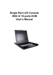
TFT-LCD Monitor ADMNM17LCD ADMNM19LCD ADMNM17LCDX ADMNM19LCDX INSTRUCTION MANUAL Please read this manual thoroughly before use, and keep it handy for future reference. Document Number: 20051220-10B Part Number: V531-LB17T-T01 Version: V2.1 WARNING: TO REDUCE THE RISK OF FIRE OR ELECTRIC SHOCK, DO NOT EXPOSE THIS PRODUCT TO RAIN OR MOISTURE. DO NOT INSERT ANY METALLIC OBJECT THROUGH VENTILATION GRILLS. CAUTION: CAUTION Explanation of Graphical Symbols The lightning flash with arrowhead symbol, within an equilateral triangle, is intended to alert the user to the presence of un-insulated "dangerous voltage" within the product's enclosure that may be of sufficient magnitude to constitute a risk of electric shock to persons. The exclamation point within an equilateral triangle is intended to alert the user to the presence of important operating and maintenance (servicing) instructions in the literature accompanying the product. Precautions Safety Should any liquid or solid object fall into the cabinet, unplug the unit and have it checked by the qualified personnel before operating it any further. Installation Do not install the unit in an extremely hot or humid place or in a place subject to excessive dust or mechanical vibration. The unit is not designed to be waterproof. Exposure to rain or water may damage the unit. Unplug the unit from the wall outlet if it is not going to be used for several days or more. To disconnect the cord, pull it out by the plug. Never pull the cord itself. Cleaning Clean the unit with a slightly damp soft cloth. Use a mild household detergent. Never use strong solvents such as thinners or benzene as they might damage the finish of the unit. Allow adequate air circulation to prevent internal heat build-up. Do not place the unit on surfaces (rugs, blankets, etc.) or near materials(curtains, draperies) that may block the ventilation holes. Retain the original carton and packing materials for safe transport of this unit in the future. 2 FCC Compliance Statement Information to the user: This equipment has been tested and found to comply with the limits for a class B digital device, pursuant to part 15 of the FCC rules. These limits are designed to provide reasonable protection against harmful interference in a residential installation. This equipment generates, uses and can radiate radio frequency energy and, if not installed and used in accordance with the instructions, may cause harmful interference to radio communications. However, there is no guarantee that interference will not occur in a particular installation. If this equipment does cause harmful interference to radio or television reception, This can be determined by turning the equipment off and on, the user is encouraged to try to correct the interference by one on more of the following measures: - Re-orient or relocate the receiving antenna - Increase the separation between the equipment and receiver. - Connect the equipment into an outlet on a circuit different from that to which the receiver is connected. - Consult the dealer or an experienced radio/TV technician for help CAUTION: Changes or modifications not expressly approved by the party responsible for compliance could void the user's authority to operate the equipment. This product complies with other various regional and safety regulations such as FCC, CE. These certifications are noted on the product label. 3 Important Safeguards 9. 1. READ INSTRUCTIONS -- All the safety and operating instructions should be read before the appliance is operated. 2. RETAIN INSTRUCTIONS -- The safety and operating instructions should be retained for future reference. 3. CLEANING -- Unplug video monitor or equipment from the wall outlet before cleaning. Do not use liquid cleaners or aerosol cleaners. Use a damp cloth for cleaning. POWER SOURCES -- Video monitor or equipment should be operated only from the type of power source indicated on the marking label. If you are not sure of the type of power supplied to your home, consult your video monitor or equipment dealer or local power company. For video monitor or equipment designed to operate from battery power refer to the operating instructions. 10. GROUNDING OR POLARIZATION -This video monitor may be equipped with a polarized alternating - current line plug (a plug having one blade wider than the other). This plug will fit into the power outlet only one way. This is a safety feature. If you are unable to insert the plug fully into the outlet, try reversing the plug. If the plug should still fail to fit, contact your electrician to replace your obsolete outlet. Do not defeat the safety purpose of the polarized plug. 4. ATTACHMENTS -- Do not use attachments not recommended by the video monitor or equipment manufacturer as they may result in the risk of fire, electric shock or injury to persons. 5. WATER AND MOISTURE -- Do not use video monitor or equipment near water -for example, near a bathtub, washbowl, kitchen sink, laundry tub, in a wet basement, or near a swimming pool, or the like. 11. Alternate Warnings - This video monitor is equipped with a three-wire grounding-type plug, a plug having a third (grounding) pin. This plug will only fit into a grounding-type power outlet. This is a safety feature. If you are unable to insert the plug into the outlet, contact your electrician to replace your obsolete outlet. Do not defeat the safety purpose of the grounding-type plug. 6. ACCESSORIES -- Do not place video monitor or equipment on an unstable cart, stand or table. The video monitor or equipment may fall, causing serious injury to a child or adult, and serious damage to the equipment. Wall or shelf mounting should follow the manufacturer's instructions, and should use a mounting kit approved by the manufacturer. 12. POWER CORDS -- Do not allow anything to rest on the power cord. Do not locate video monitor or equipment where the cord will be abused by persons walking on it. 7. Video monitor or equipment and cart combinations should be moved with care. Quick stops, excessive force, and uneven surfaces may cause the equipment and cart combination to overturn. 13. HEED WARNINGS -- Follow all instructions marked on the video monitor or equipment. 14. LIGHTNING -- For added protection for video monitor or equipment during a lightning storm, or when it is left unattended and unused for long periods of time, unplug it from the wall outlet and disconnect the antenna or cable system. This will prevent damage to the video product due to lightning and power-line surges. 8. VENTILATION -- Slots and openings in the cabinet and the back or bottom are provided for ventilation, and to ensure reliable operation of the video monitor or equipment and to protect it from overheating. These openings must not be blocked or covered. The openings should never be blocked by placing the video monitor or equipment on a bed, sofa, rug, or other similar surface. Video monitor or equipment should never be placed near or over a radiator or heat register. Video monitor or equipment receiver should not be placed in a built-in installation such as a bookcase unless proper ventilation is provided. 15. OVERLOADING --Do not overload wall outlets and extension cords as this can result in a risk of fire or electric shock. 4 Important Safeguards 19. SAFETY CHECK -- Upon completion of any service or repairs to this video product, ask the service technician to perform safety checks to determine that the video product is in proper operating condition. 16. OBJECT AND LIQUID ENTRY -- Never push objects of any kind into video monitor or equipment through openings as they may touch dangerous voltage points or short-out parts that could result in a fire or electric shock. Never spill liquid of any kind on the product. 20. FIELD INSTALLATION -- This installation should be made by a qualified service person and should conform to all local codes. 17. SERVICING -- Do not attempt to service video monitor or equipment yourself as opening or removing covers may expose you to dangerous voltage or other hazards. Refer all servicing to qualified service personnel. 18. DAMAGE REQUIRING SERVICE -Unplug video monitor or equipment from the wall outlet and refer servicing to qualified service personnel under the following conditions: A. B. C. D. E. F. When the power-supply cord or the plug has been damaged. If liquid has spilled, or objects have fallen into the video product. If the video product has been exposed to rain or water. If the video product does not operate normally by following the operating instructions, adjust only those controls that are covered by the operating instructions as an improper adjustment of other controls may result in damage and will often require extensive work by a qualified technician to restore the video product to its normal operation. If the video product has been dropped, or the cabinet damaged. When the video product exhibits a distinct change in performance -- this indicates a need for service. 5 Installation Guide Accessory All of accessories have been tested and qualified. Do not use any non-qualified accessories with this LCD monitor. Please check all accessories before installation LCD monitor. TFT-LCD monitor x 1 USA AC power cord x 1 VGA cable x 1 European AC power x 1 for ADMNM17LCD and ADMNM19LCD Model Only User manual x 1 European AC power cord x 1 UK AC power cord x 1 for ADMNM17LCDX and ADMNM19LCDX Model Only CD containing multi language instructions x 1 Instruction Reading Guide Forbid label: Warning that failure to observe could result in damage while operating or installing the monitor incorrectly. Danger label: To draw installers attention that if caution is not observed potential injury to the installer or other persons could occur. Attention label: The user should pay attention to the explanation in the manual for this item while configuring the monitor. Doubt label: A warning that the installers may need to consult with others for more details on option before proceeding. Suggestion label: The user may like to consider this for an optimal setting. 6 Contents ……………………………………………………2 ……………………………………3 Important Safeguards …………………………………………4 Installation Guide ………………………………………………6 Contents ……………………………………………………7 Quick installation ………………………………………………8 Features ……………………………………………………9 Resolution Support …………………………………………10 Operating Instructions Controls ……………………………………11 Backside Connections …………………………………………12 OSD Architecture ………………………………………………13 A. OSD Tree ………………………………………………13 B. General Setup ………………………………………………14 C. Advanced General Setup ……………………………………15 D. CVBS / S-Video Setup …………………………………………16 E. CVBS / S-Video Advanced Setup ………………………………17 F. VGA Setup ………………………………………………18 G. VGA Advanced Setup …………………………………………19 H. Audio Setup ………………………………………………20 I. PIP Setup ………………………………………………21 J. RS-485 Setup ………………………………………………22 Mounting Guide ………………………………………………23 A. Desktop ………………………………………………23 B. VESA Bracket ………………………………………………24 C. Rack Mount Bracket …………………………………………25 Typical Device Connections ………………………………………26 Specification ………………………………………………27 Appendixes ………………………………………………28 Dimensions……………………………………………………30 z Warning z FCC Compliance Statement z z z z z z z z z z z z z z -7- Quick Installation For instructions on wall mounting or rack mounting, see page 23 of this user guide. 1 Connect power cord 2 Connect video cable • Make sure both the LCD display and computer are turned OFF • Connect the video cable from the LCD display to the computer. 3 Turn ON LCD display and computer • Turn ON the LCD display, then turn ON the computer. This sequence (LCD display before computer) is important. 4 Windows users: Set the timing mode (resolution and refresh rate) Example: 1280 x 1024 @ 60 Hz. For instructions on changing the resolution and refresh rate, see the graphic card’s user guide Installation is complete. Enjoy your new LCD display. -8- Features General z z z 1280 x RGB x 1024 TFT LCD Panel. Advance control OSD menu. High contrast and brightness PC z z z z 1 analog RGB signal input. Compatible with SXGA (1280 x 1024) resolution. Support vertical refresh rate up to 75 Hz for VESA standard specification. Automatic detection or manual configuration of optimal refresh and synchronization rates for VGA and composite signals. VGA screen horizontal / vertical position and width adjustment. z VIDEO z z z z z z z z z z z z z z z z z 2 composite (CVBS) signal input. 2 composite (CVBS) signal loop-out. Video loop-out auto termination (75 Ohms). 1 Y/C (S-Video) separate signal input. Video input support NTSC / PAL / SECAM video standards. High precision Y/C separation 3D comb filter for NTSC / PAL signal. 3D concurrent noise reduction. Time base correction (TBC). Chroma transient improvement(CTI) Built-in high quality 3D de-interlace for NTSC / PAL signal. 9300K / 6500K / User custom color temperatures. Provide PIP (Picture In Picture) function. Provide VOV (Video On Video) function. Support 3:2 and 2:2 pull-down for film source. AGC (Auto Gain Control) function for all video signals. Video screen horizontal / vertical position and width adjustment. Provide over / under / full scan function. AUDIO z z z z 2x stereo audio input by RCA Jack. 2W+2W speaker. Auto audio mute during video loss. Balance, Bass and Treble audio controls. Other z z z z z z z z z z z z z z z Key-lock function. Programmable power on option. Signal auto searching. Power latching. Power failure auto recover. Programmable sleep mode for screen. Easily selectable video switching function. Multi language (English, German, French, Spain, Japan, Chinese), RS-485 interface for remote control. ISP functions for upgrade firmware. Support VESA 75 x 75 and VESA 100 x 100 mounting standard. Support Desktop bracket. Support Rack mount bracket (optional). Wide voltage range AC 100~240V / 50/60Hz input. Power consumption 40W@110VAC/60Hz. -9- Resolution Support VGA resolution table Resolution Symbol H Freq. V Freq. Pixel Remark 640 x 480 640-60 31.469 59.941 25.175 VESA 640 x 480 640-72 37.861 72.810 31.500 VESA 640 x 480 640-75 37.500 75.000 31.500 VESA 800 x 600 800-56 35.156 56.250 36.000 VESA 800 x 600 800-60 37.879 60.317 40.000 VESA 800 x 600 800-72 48.077 72.188 50.000 VESA 800 x 600 800-75 46.875 75.000 49.500 VESA 1024 x 768 1024-60 48.363 60.004 65.000 VESA 1024 x 768 1024-70 56.476 70.069 75.000 VESA 1024 x 768 1024-75 60.023 75.029 78.750 VESA 1280 x 1024 1280-60 63.981 60.020 108.000 VESA 1280 x 1024 1280-75 79.976 75.024 135.000 VESA Please refer to page 18 for information on automatic input sync optimization. Please note, selecting frequencies outside these ranges may result in an abnormal image or damage to the monitor - 10 - Operating Instructions - Controls Power Monitor ON /OFF. If switched OFF with this button, monitor will be in standby state. Light indicate: Green – Power On Yellow – Standby mode. Red – Power Off Adjust UP / PIP OSD Menu mode - select item above. Normal operating mode - Turn PIP ON/OFF, select PIP source. Adjust Down / Scan Mode OSD Menu mode - select item below. Normal operating mode - Select input sequence. Adjust RIGHT / Volume Up OSD Menu mode - select item to the right Normal operating mode - Increase Volume level. Adjust LEFT / Volume Down OSD Menu mode - select item to the left. Normal operating mode - Decrease volume level. MENU OSD menu ON or ENTER control. EXIT / Auto OSD Menu mode - exit to previous menu. Exit top menu. Normal operating mode - Force auto sync rate adjustment for VGA input. INPUT Select input from CVBS1, CVBS2, S-Video, VGA. - 11 - AUDIO1 Connections 1 PC-AUDIO: Audio signal input for VGA channel. ○ 2 AUDIO 1: Audio signal input 1 for CVBS1 and ○ S-Video. Normally, RED is for right channel; WHITE is for left channel. 3 AUDIO 2: Audio signal input 1 for CVBS2. ○ Normally, RED is for right channel; WHITE is for left channel. 4 S-VIDEO: Video signal input for Y/C separate ○ signal. 5 CVBS2 OUT: Video auto termination loop-out ○ for CVBS2 IN signal. Auto termination impedance are 75 Ohms. 6 CVBS 2 IN: composite video signal input for ○ CVBS2 channel. 7 CVBS1 OUT: Video auto termination loop-out ○ for CVBS1 IN signal. Auto termination impedance are 75 Ohms. 8 CVBS1 IN: composite video signal input for ○ CVBS1 channel. 9 RS-485: RS-485 remote control twisted pair ○ input. 10 VGA: Analog RGB signal input for VGA. ○ 11 AC IN: 100~240VAC power input. ○ Incorrect signal level or frequency may cause damage to the monitor or injure the user. - 12 - OSD Architecture OSD Menu Tree - 13 - OSD Architecture General Setup z Input auto search: Allows monitor to search for an input signal at power on. This function is only available once when the monitor is first turned ON. z z Power on default: Set the signal input priority at power ON. CVBS1: Set channel to AV1 when power is turned ON. CVBS2: Set channel to AV2 when power is turned ON. S-Video: Set channel to S-Video when power is turned ON. VGA: Set channel to VGA when power is turned ON. None: No changing. Auto power on: Allows the monitor to memorize the power status prior to power failure and resume the same status on restoration of power. ON: Set ON to enable the function. OFF: Set OFF to disable the function. Suggest set Auto power on to “ON”. z Language: Allows user to select the OSD menu Languages in English, German, French, Spanish, Italian. z Key lock: This function is from preventing an unauthorized person to accessing the OSD settings. ON: Key-lock function enabled. OFF: Key-lock function disabled. If key-lock function is enabled, the monitor will auto lock its keypad 1 minute after the last key press. To unlock the keypad, press and hold the menu button for 5 seconds. z Back light: Allows user to adjust panel backlight level. z Factory reset: Reset the monitor to the original factory settings. - 14 - OSD Architecture General Advanced Setup z V-loss setup: Places monitor into sleep mode after video loss. Delay period is defined by slide bar. When the slide bar is set to 0, video loss sleep is disabled and its status is shown as below: z OSD Position: This feature allows user configuration of OSD menu position on screen. Area1: OSD menu on top-left. Area 1 Area 4 Area2: OSD menu on bottom-left. Area 3 Area3: OSD menu on screen center Area 5 Area 2 Area4: OSD menu on top-right. Area5: OSD menu on bottom-right. z Logo Display: This feature allows user turn on/off company logo at power on. ON: Show company logo at power on. OFF: Hide company logo. z Display: Show / Hide channel title. ON: Show channel title OFF: Hide channel title - 15 - OSD Architecture CVBS / S-Video Setup z Brightness: Adjusts the overall picture shade and brightness. z Contrast: Permits adjustment for contrast between light or dark areas of the picture. z Color: Adds color to the black and white picture content (of a color signal), and is usually set for viewer’s preference in color saturation. z Hue: Adjusts the shade of all the colors on the screen, but is most noticeable to the eye in reds and yellows, and is also usually set for pleasing face tones (NTSC only). z Sharpness: Sets the desired sharpness of the image. z Color temperature: Selects color temperature of 6500°K, 9300°K or User. z Factory reset: Reset the monitor to the original factory settings. - 16 - OSD Architecture CVBS / S-Video Advanced Setup z Scan Mode: This function allows user to select monitor display format. Under: this feature displays the picture with all extremities of the source image visible (reduced size) Over: this feature displays the picture with all extremities of the source image hidden (increased size) Full: this feature displays the picture with all extremities of the source image aligned with the visible area of the screen (full size) z H-position: Adjusts horizontal position of image. z V-position: Adjusts vertical position of image. z Comb filter: Allows the user to manually turn the video comb filter ON/OFF. ON: Enable comb filter. OFF: Disable comb filter. Suggestion set Comb filter to “ON”. - 17 - OSD Architecture VGA Setup z Input sync. auto: This feature allows the user to auto-optimize the displayed picture under VGA mode. z Brightness: Adjusts the overall picture shade and brightness. z Contrast: Permits adjustment for contrast between light or dark areas of the picture. z Color temperature: Selects color temperature of 6500°K, 9300°K or User. z Factory reset: Reset the monitor to the original factory settings. - 18 - OSD Architecture VGA Advanced Setup z H-Position: Adjusts horizontal position of image. z V-Position: Adjusts vertical position of image. z Picture stretch: Is used to adjust the width of the image. It alters the frequency of the pixel clock across one line and there for may affect picture position as well as width. z Input sync. manual: Is used to adjust for optimum image clarity. It adjusts the sampling phase of each line. When incorrectly set, the image may be unclear. Improper adjustment will cause image loss. Improper adjustment will cause image loss. z White balance: Optimizes the white reference for grayscale images. - 19 - OSD Architecture Audio Setup z Mute: Select Audio Mute. z Volume: Set audio volume level for internal speakers. z Treble: Adjusts the treble content of the sound from the internal speakers. z Bass: Adjusts the bass content of the sound from the internal speakers. z Balance: Adjusts the audio speakers’ balance. z Factory reset: Reset the monitor to the original factory settings. - 20 - OSD Architecture PIP Setup z Source: This feature allows a user to select the video input signal to be displayed when in PIP mode. CVBS1: Turn on the PIP, and set PIP channel source to CVBS1. CVBS2: Turn on the PIP, and set PIP channel source to CVBS2. S-Video: Turn on the PIP, and set PIP channel source to S-Video. OFF: Turn off PIP window. z Swap: swaps the main screen image with the content of the PIP. z Bezel size: Adjusts the thickness of the PIP window border. z Size: Adjusts the overall size of the PIP window. z H-Position: Adjusts the horizontal position of the PIP window. z V-Position: Adjusts the vertical position of the PIP window. - 21 - OSD Architecture RS-485 Setup z RS-485 format: Enabled / Disable RS-485 protocol format. z ID address: Sets RS485 ID for remote connection and control. z Baud rate: Displays RS485 baud rate for remote connection and control. (Note, this is not user configurable) Refer to the pin assignment on right for the correct connection. Used 0.654 conductor twisted pair cable for an extended distances up to 1000m. Contact your sales representatives for the details on the communication functions such as the protocol of the device. - 22 - Installation Guide Desktop 1 With the monitor on a flat surface, hold the base at one side with one hand and draw the screen upwards with the other hand, until the required tilt angle is achieved. Click! A noticeable "click" will be heard, and felt, as the screen is moved into the normal range of tilt.(For detailed range, see image below) 2 Do not touch the display area of the screen with hands, fingers or any sharp object, or use tools to raise the screen, otherwise damage to the screen may occur. Do not place fingers into the hinge area, otherwise injury may occur when raising the screen. Only attempt to raise the screen on a flat, level and stable surface, such as a tabletop. If you have any support questions relating to this operation, please contact Tyco Technical Support, who will be pleased to assist you. When using the desk stand, only operate the panel on a flat surface, which is no more than 10 degrees from level. 3 Optimum viewing angles are obtained when viewing the monitor when it is set between +20º and -5º from vertical. Adjust the tilt angle for optimum image quality. - 23 - Installation Guide VESA Bracket 1 Holding the front of the base with one hand, use the other hand to push the top of the casing back, until it lies flat. Do not insert fingers onto the hinge area, otherwise injury may occur when folding down the screen. The screen should only be folded down of a flat, stable, level surface. 2 Lay the LCD display face down on a towel or blanket. Note the 4 screws that secure the hinge on the lower part of the back casing. These may be removed to release the desk mount bracket if required. 3 Attach a VESA compatible mounting bracket to the appropriate set of holes (both 75mm x 75mm and 100mm x 100mm are supported) Use only M4 x 12mm screws to mount the VESA bracket, failure to observe this may cause serious injury. Ensure that the VESA bracket has an adequate size mounting plate, screws and or fixings to support the weight of the monitor and bracket to the surface to which it is being attached. Failure to observe this may cause serious injury. If there is any doubt of the suitability of a mount or fixing method, a qualified technician should be consulted. - 24 - Installation Guide Optional Accessory ADMNRKT17 or ADMNRKT19 1 Remove the desk mount bracket as detailed in the previous section. 2 Fix the rack mount brackets to the two sides of the monitor as shown below. Use the supplied M3 screws to mount the monitor to the brackets. Failure to observe this may result in serious injury. 3 Fix the monitor in rack. Use screws applicable to the rack system in use. Failure to observe this may result in serious injury. If there is any doubt of the suitability of a mount or fixing method, a qualified technician should be consulted. - 25 - Typical Device Connections - 26 - Specification Pixel Type Max. Resolution Aspect Ratio Resolution / Scan for VGA / DVI Viewing Area Pixel Pitch Brightness Contrast Ratio Type Hours Backlight Type Viewing Angle (H/V) Display Color Response Time Sync. Format Frequency (Horizontal) Frequency (Vertical) Video Interface Input Interfaces VGA CVBS S-Video Audio Interface Input Power Input Signal Integrated Speakers Front Panel Controls Indicators Remote Control PIP & VOV Comb Filter De-interlace Noise reduction TBS CTI AGC 3:2 2:2 pull-down Non-linear scaling Power Failure Auto Recover Color Temperature Special Features Scan Mode Key Lock Rack mount Type Power Latching Power on Option Auto signal searching RS-485 PVM expand CDS light sensor ISP function Expand interface Language Rack Tilt Angle / Swivel VESA Mounting Power Type Power Supply Temp (Oper.) Max. Temp Temp (Storage) Dimension 17" Normal white 1280 x RGB x 1024 4:3 640 x 480 @ 60/72/75Hz 800 x 600 @ 56/60/72/75 Hz 19” Normal black 1280 x RGB x 1024 4:3 640 x 480 @ 60/72/75 Hz 800 x 600 @ 56/60/72/75 Hz 1024 x 768 @ 60/70/75 Hz 1280 x 1024 @ 60 / 75 Hz 1024 x 768 @ 60/70/75 Hz 1280 x 1024 @ 60 / 75 Hz 337.920(H) x 270.336(V) 376.32(H) x 301.056(V) 0.264 x 0.264 mm 0.294 x 0.294 mm 420 cd/m2 450 cd/m2 500:1 450:1 4CCFL 4CCFL 50,000 hr(Typ) 50,000 hr(Typ) 160/160 140/135 16.2M colors 16.2M colors 8ms(tr+tf) 12ms(tr+tf) NTSC / PAL / SECAM PC: 31.5K~80KHz Video 15750 / 15625Hz (NTSC/PAL/SECAM) PC: 56Hz~75Hz Video: 50 / 60Hz D-Sub 15 In x 1, Video In x 2 (BNC), Video Out x 2 (BNC), S-Video In x 1 Yes, x 1 Yes, x 2 Yes, x 1 Audio In x 2, PC Phone In x 1 AC Socket In x 1 Composite signal 0.5~2Vpp / 75ohm (Auto Termination), Y Signal 1Vpp, C signal 0.3 Vpp Yes (2W + 2W) Power, Adjust Up/Down/Left/Right, Menu, Exit, Input LED, Power on, Stand by, Sleep No VOV + PIP 3D (NTSC / PAL) 3D (NTSC / PAL) 3D Yes Yes Yes Yes No Yes 9300 ゚ K / 6500 ゚ K / User Over / Full / Under Yes Yes Yes CVBS1 / CVBS2 / S Video / VGA Yes Yes No No Yes No English, German, French, Spain, Japan, Chinese up 15° / down 15° VESA 75 / VESA 100 AC 100~240 VAC 50/60Hz Internal 0 ゚ C ~ 35 ゚ C 50 ゚ C -10 ゚ C ~ 60 ゚ C 387.5 x 424.9 x 92.48 mm 425 x 440.2 x 92.48 mm - 27 - Appendixes Check the information in this section to see if the problems can be solved before requesting repair: The consumers are only allowed to solve the problems described as below. Any unauthorized product modification, or failure to follow instructions supplied with the product will void the warranty immediately. Problem: No Power indication Make sure power cord is correctly. Make sure power voltage range is between 100~240Vac. Problem: No image Make sure power button is ON. Check whether the LCD monitor and computer or video devices power cords are plugged in and that there is a supply of power. Problem: No signal Check the signal connection between the computer and LCD monitor. Make sure the computer power is ON. Make sure the correct input is selected. Problem: “Out of Range” Check the computer image output resolution and frequency and compare the value with preset value (please refer to page 10). Problem: Fuzzy image Adjust “Input sync. manual” in VGA advance setup. Problem: Image too bright or Image too dark Adjust brightness and contrast by OSD. Problem: Irregular image Check the signal connection between the computer and LCD monitor. Perform “Input sync. auto”. Problem: Distorted image Reset LCD monitor. (perform the “Factory Reset” function by OSD) Problem: Image is not centered Size is not appropriate Take off extra accessories. (such as looped out video signal) Use OSD image menu to adjust H-Position and V-Position. Check image size setting. Perform “Input sync. auto”. - 28 - Appendixes Problem: Uneven color or Color too dark or Dark area distorted Use OSD “Color” function to adjust color setting. Problem: White color is not white Check “Color temperature” is correct. Use OSD “Color” function to adjust color setting. Use OSD “Hue” function to adjust color setting. Problem: Can not adjust LCD monitor with buttons in the front. Check OSD “Key lock” function is ON. Problem: All of image can not be seen on the screen Use OSD “Scan mode” function to adjust screen size. - 29 - Dimensions - ADMNM17LCD / ADMNM17LCDX 92.48mm (3”) 424.90mm (16.73") 354mm (13.94") 387.5mm (15.26") 195.7mm (7.70") - 30 - Dimensions - ADMNM19LCD / ADMNM19LCDX 92.48mm (3”) 424.90mm (16.73") 354mm (13.94") 425mm (16.73") 195.7mm (7.70") - 31 -