1
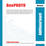
All Mikroelektronika’s development systems feature a large number of peripheral
modules expanding microcontroller’s range of application and making the
process of program testing easier. In addition to these modules, it is also
possible to use numerous additional modules linked to the development system
through the I/O port connectors. Some of these additional modules can operate
as stand-alone devices without being connected to the microcontroller.
Manual
Additional Board
Easy Bee3
™
MikroElektronika
Easy Bee3 Additional Board
The Easy Bee3 additional board is used for wireless communication at short distances and with low power consumption. Wireless
communication is enabled due to a ZigBee module MRF24J40MA provided on the Easy Bee3 board. Some of the key features of this
module are: data rate up to 250kbps, 2.4GHz operating frequency, power consumption ~20mA, up to 120 m range, etc. Connection
between the additional board and a microcontroller is established via a 2x5 female connector supplied on the additinal board and a 2x5
male connector on the development system. Communication between them is performed via a Serial Peripheral Interface (SPI). Since
the additional board may be connected to different development systems, it is necessary to select the appropriate microcontroller pins
to be used for SPI communication. DIP switches SW1 and SW2 on the additional board are used for this purpose. The bottom of the
board provides a table indicating which switches on the DIP switches SW1 and SW2 should be used depending on the development
system in use, Figure 2.
ZigBee module MRF24J40MA
Ends of flat cabels are provided
with 2x5 female connectors
Figure 1: Easy Bee3 additional board
The ZigBee module requires the 3.3V power supply voltage for its operation. Since
different development systems require different voltage levels, it is necessary to adjust the
additional board’s voltage level to the development system’s voltage level. It is performed
by a voltage regulator supplied on the additiona board. Jumper J1 is used to select power
supply voltage for the additional board. If the board is connected to a 5V development
system, it is necessary to place jumper J1 in the 5V position. For 3.3V development
systems, jumper J1 should be placed in the 3.3V position. In addition to the voltage level
adjustment, it is also necessary to adjust voltage signals provided by the ZigBee module.
The additional board features transceivers 74LVCC3245 and 74LVC1T45 that serves as
voltage level translators.
Figure 2: Back of the Easy Bee3 board
MikroElektronika
Figure 3: Easy Bee3 additional board
Figure 4: Easy Bee3 additional board connected to a development system
MikroElektronika
MikroElektronika
If you have any questions, comments or business proposals, do not hesitate to contact us at [email protected]
If you are experiencing some problems with any of our products or just need additional information, please place your ticket at
www.mikroe.com/en/support
If you want to learn more about our products, please visit our website at www.mikroe.com