1
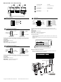
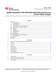
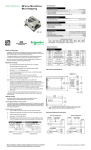
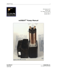
Quick Reference
MicroLYNX-4/7
High performance microstepping
system
General Specifications
Electrical Specifications
MicroLYNX -4
MicroLYNX-7
MicroLYNX -4
MicroLYNX-7
MicroLYNX -4
MicroLYNX-7
MicroLYNX -4
MicroLYNX-7
Input Voltage (+V) Range*
Max Power Supply Current
Output Current (RMS)
Output Current (Peak)
+12 to +48 VDC
+24 to +75 VDC
2.0 Amps
4.0 Amps
3.0 Amps
5.0 Amps
4.2 Amps
7.0 Amps
*Actual power supply current will depend on voltage and load.
Environmental Specifications
Ambient Operating Temperature
Storage Temperature
Humidity (non-condensing)
0°C to +50°C
-20°C to +70°C
0 to 90%
I/O Specifications
General Purpose I/O - Number and Type*
6 I/O programmable as inputs or
outputs (sinking or sourcing)
I/O Points
General Purpose I/O - Electrical
Inputs
Outputs
Output Sink Current
Pull-ups (individually switchable)
Pull-up Voltage (internal)
Pull-up Voltage (external)
TTL up to +24 VDC
Up to +24 VDC
350 mA
7.5 kΩ
+5 VDC
+24 VDC
Over Temp, Short Circuit,
Inductive Clamp
Common to all 6 I/O
Protection (Sinking)
Isolated Ground
*I/O may be expanded through use of expansion modules available separately. Available modules:
Isolated general purpose I/O, High speed differential I/O, Analog input and analog output.
Notes and Warnings
Communications Specifications
Installation, configuration and maintenance must be carried out by qualified
technicians only. You must have detailed information to be able to carry out this
work. This information can be found in the user manual.
• Unexpected dangers may be encountered when working with this product!
• Incorrect use may destroy this product and connected components!
The user manual are not included, but may be obtained from the Internet at:
http://www.imshome.com/downloads/manuals.html.
Required for Setup*
COM Port 1
COM Port 2
Protocol
BAUD Rate
# of bits/character
Parity
Handshake
Error Checking
Modes
Isolated Ground
•
PC running Microsoft® Windows XP Service Pack 2 or greater.
Motion Specifications
•
IMS Terminal integrated program editor and terminal emulator (available
online).
Microstep Resolution
Number of Resolutions
•
+12 to +48 VDC, 2A (-4) or +24 to +75 VDC, 3.5A (-7) unregulated linear
or switching power supply.
•
RS-232 or RS-485 communications converter.
•
Stepping motor appropriately sized for your MicroLYNX system.
•
22 AWG wire for logic and I/O, 18 AWG wire (-4) or 16 AWG wire (-7) for
power supply. Shielded twisted pairs recommended.
•
Basic hand tools: wire cutter/stripper, screw driver.
400
6400
RS-232
RS-485
4.8 to 38.8 kbps
8
None
None
16 bit CRC (binary mode)
ASCII or binary
Common to COM 1 and COM 2
14
Available Microsteps Per Revolution
800
1000
1600
2000
3200
10000
12800 25000 25600
50000
5000
51200
Software Specifications
Program Storage Type/Size
User Program Labels and Variables
Party Mode Addresses
Flash/8175 Bytes
291
62
Getting Started
All documentation, software and resources are available online at:
http://www.imshome.com/products/mdrive_motor_driver.html.
Connecting Communications — RS-232 or RS-485
1.
Connect communications converter to MicroLYNX and PC (follow instructions supplied by manufacturer).
2.
Install the communication converter drivers onto PC (supplied by manufacturer).
3.
Install and open IMS Terminal.
4.
From the “Edit” menu select “Preferences, click the “Comm Settings” tab.
5.
Select the radio box labeled “uLynx”, select the Comm port used by your
communications device.
6.
Apply power to MicroLYNX.
7.
Within IMS Terminal, click into the Terminal Window (shown below).
8.
Key in CTRL+C. The sign-on message: “Copyright 2001-2008 by Intelligent Motion Systems, Inc.” should appear, verifying that communications
is active.
Program Editor
Window
Mechanical Specifications
Dimensions in inches (mm)
Terminal Emulator
Window
>Copyright 2001-2008 by Intelligent Motion Systems. Inc.
All documentation, software, program examples and resources are available
online at: http://www.imshome.com/products/discrete_drivers.html.
MicroLYNX-4/7 Quick Reference R020410
MicroLYNX -4/7 Connectivity
P3
2
Connector Style
6-pin terminal............................... DC power and motor
P1
3
Function
P2
7-pin terminal.............................. Communications
10-pin header.............................. Communications
P3
8-pin terminal............................... I/O
10-pin header.............................. I/O
GND
PHASE B
V+
POWER
SUPPLY
PHASE B
MICRO
PHASE A
COMMUNICATIONS
TM
GROUP 20 I/O
P1
EXPANSION BOARDS
PHASE A
1
P2
P1
Power and Motor
P3
6-pin pluggable screw terminal
Motor Phase A
Motor Phase A
Motor Phase B
Motor Phase B
+V
Ground
I/O Points
10-pin header or 8-pin pluggable terminal
1: I/O 21
3:Vpullup
5: Fault+ In
7: Fault – In
9: I/O GND
1: Vpullup
2: I/O 21
3: I/O 22
4: I/O 23
5: I/O 24
6: I/O 25
7: I/O 26
8: I/O GND
2: I/O 22
4: I/O 23
6: I/O 24
8: I/O 25
10: I/O 26
10-pin header
P2
RS-232 Communications
8-pin terminal
The MicroLYNX I/O interface is available with two connector options: an 8-pin
pluggable terminal or 10-pin header. For interfacing to these connectors we recommend:
10-pin header or 7-pin pluggable terminal
1: RX
2: TX
2: TX
3: RX
5: CGND
8-pin terminal
22 AWG shielded twisted pairs.
10-pin header
Ribbon cable: Digikey P/N MC10G-300-ND
Connector shell: AMP P/N 3-1437026-4
6: CGND
10: CGND
10-pin header
I/O Switch Settings
The I/O internal 7.5 k pullup resistors may be switched in or out to set the I/O as
sinking or sourcing.
7-pin terminal
The MicroLYNX communication interface is available with two connector options: a
7-pin pluggable terminal or 10-pin header. For interfacing to these connectors we
recommend:
The switch bank is located on the right side of the MicroLYNX with the front plate
facing you.
7-pin terminal:
22 AWG shielded twisted pairs.
10-pin header:
Ribbon cable: Digikey P/N MC10G-300-ND
Connector shell: AMP P/N 3-1437026-4
P2
RS-485 Communications
10-pin header or 7-pin pluggable terminal
3: RX
5: CGND
7: RX–
9: TX+
3: RX–
4: RX+
5: TX–
6: CGND
7: TX+
6: RX+
8: TX–
10: CGND
10-pin header
Expansion Module Installation
Please see the expansion module quick reference or the MicroLYNX product
manual for specifications and pin configuration.
Module
7-pin terminal
# allowed
Isolated I/O
High speed differential I/O
12- channel I/O
Analog input/joystick
Analog output
The MicroLYNX communication interface is available with two connector options: a
7-pin pluggable terminal or 10-pin header. For interfacing to these connectors we
recommend:
7-pin terminal
22 AWG shielded twisted pairs.
10-pin header
Ribbon cable:
Digikey P/N MC10G-300-ND
Connector shell: AMP P/N 3-1437026-4
1
Y
N
Y
Y
Y
3
2
1
1
3
Slots
2
Y
Y
Y
Y
Y
3
Y
Y
N
Y
Y
ISOLATED DIGITAL I/0
TERMINAL BLOCK
1. V PULL-UP
Install Label as shown
2. I/O CHANNEL 1
3. I/O CHANNEL 2
4. I/O CHANNEL 3
5. I/O CHANNEL 4
6. I/O CHANNEL 5
7. I/O CHANNEL 6
8. I/O GROUND
F
B
SLOT#
[1] [2] [3]
A
L
A
IT
K
IG
C
D
LO
D
E
B
T
L
A
LA
P 1
O
IN
IS
M
-U L
R LL NE 2
TE PU AN EL 3
V CH NN EL
A
1.
4
I.O CH NN EL
A
2.
5
I/O CH NN EL
A
3.
6
I/O CH NN EL
A
4.
I/O CH NN D
A N
5.
I/O CH U
]
O
6.
[3
I/O GR
]
7.
[2
]
I/O
[1
8.
I/0
• ISOLATED DIGITAL I/0
#
T
O
L
S
C
D
E
Copyright © Schneider Electric Motion USA
www.schneider-electric-motion.us
A
Remove
Desired
Panel
• ISOLATED DIGITAL I/0
Install Label as shown