1
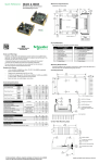
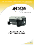
Quick Reference
MForce MicroDrive
Microstepping
Specifications
Electrical Specifications
Input Voltage (+V) Range*
Max Power Supply Current (Per MForce MicroDrive)*
Output Current (RMS)
Output Current (Peak)
*Actual Power Supply Current will depend on voltage and load.
+12 to +48 VDC
3.0 A
3.0 Amps
4.2 Amps
Environmental Specifications
Operating Temperature — measured at the heat sink
(non-condensing humidity)
-40°C to +85°C
Isolated Input Specifications
Step Clock, Direction and Enable
Voltage Range (Sinking or Sourcing)
Current (+5V Max)
Current (+24V Max)
+5 to +24 VDC
8.7 mA
14.6 mA
Motion Specifications
Digital Filter Range
Clock Types
Step Frequency (Max)
Step Frequency Minimum Pulse Width
Number of Microstep Resolution Settings
50 nS to 12.9 μS (10 MHz to 38.8 kHz)
Step/Direction, Up/Down, Quadrature
5 MHz
100 nS
20
Available Microsteps Per Revolution
800
1000
1600
2000
3200
5000
25000 25600 40000
50000
51200
360001
2=1 arc minute/μstep 3=0.001 mm/μstep
200
400
12800
20000
1=0.01 deg/μstep
6400
216002
10000
254003
Setup Parameters
Setup Parameters
Notes and Warnings
Installation, configuration and maintenance must be carried out by qualified
technicians only. You must have detailed information to be able to carry out this
work. This information can be found in the user manual.
• Unexpected dangers may be encountered when working with this product!
• Incorrect use may destroy this product and connected components!
The user manual is not included, but may be obtained from the Internet at:
http://www.imshome.com/downloads/manuals.html.
Required for Setup*
•
PC running Microsoft® Windows XP Service Pack 2 or greater.
•
SPI Motor Interface (available online).
•
+12 to +48 VDC unregulated linear or switching power supply.
•
NEMA size 14, 17 or 23 stepping motor.
•
0 to 5 MHz clock signal for step clock, may be a controller high speed
output or signal generator.
•
SPST switch or controller I/O point to control axis direction.
•
SPI communications interface (recommended: MD-CC300-001 or MDCC303-001 communication converters).
Name
MHC
MRC
Function
Motor Hold Current
Motor Run Current
MSEL
Microstep Resolution
DIR
HCDT
Motor Direction Override
Hold Current Delay Time
CLK TYPE
Clock Type
CLK IOF
Clock Input Filter
EN ACT
Enable Active High/Low
USER ID
User ID
Range
0 to 100
1 to 100
See Motion
Specifications
0/1
0 or 2 - 65535
See Motion
Specifications
50 nS to 12.9 μS
(10 MHz to 38.8 kHz)
High/Low
3 Characters Viewable
ASCII
Units
Percent
Percent
μsteps/
Full Step
—
mSec
Default
5
25
256
CW
500
Step/
Direction
200 nS
(2.5MHz)
High
—
nS (MHz)
—
Viewable
ASCII
IMS
Mechanical Specifications
2X Ø 0.150
(2X Ø 3.81)
Depending on your connector configuration, you may also need:
•
If using a 7-pin pluggable terminal we recommend 22 AWG shielded
twisted pairs for logic wiring. Wire gauge for power connection varies with
the distance from the MForce and current. See the product manual.
•
I/O, Power and Communications interface to 12-pin wire crimp connector
(recommended: PD12-1434-FL3 prototype development cable).
•
Motor Interface to the 4-pin wire crimp connector (recommended: PD04MF17-FL3).
1.655 2.140
(42.05) (54.36)
1.765
(44.83)
P1
0.201
(5.11)
* If you purchased your MForce MicroDrive with a QuickStart Kit, you have
received all of the connecting cables needed for initial functional setup and
system testing.
2.325
(59.06)
Getting Started
All documentation, software and resources are available online at:
http://www.imshome.com/products/mforce_overview.html.
P2
Connecting the Motor, Power and I/O
Your MForce MicroDrive is configured with power and I/O combined on a single
connector. Please refer to the opposite side of this document for connecting details and available connectivity options including prototype development cables
and mating connector kits.
!
1.300
(33.02)
CAUTION! DO NOT REMOVE THERMAL INSULATING PAD!
Mounting without this pad can cause damage to the device
Connecting Communications
1.
Connect USB to SPI communications converter to MForce and PC.
2.
Install the communication converter drivers onto PC (available online).
3.
Install and open SPI Motor lnterface.
4.
Apply power to MForce MicroDrive.
5.
Minimum Required Connections
Sourcing Configuration
Parameters may be adjusted via two screens, the Motor Settings screen
or the I/O Settings screen (shown below), accessible via the View menu.
Controller
I/O Power
Logic Supply
+
MForce
Logic Supply
+
MForce
GND
Opto
GND
Opto
Step Out
Dir. Out
Step
Dir
Step Out
Dir. Out
Step
Dir
+
Power Supply
Stepper
Motor
Motor Settings Screen
Sinking Configuration
Controller
+V
Pwr Gnd
ØA
ØA
ØB
ØB
+
Power Supply
Stepper
Motor
+V
Pwr Gnd
ØA
ØA
ØB
ØB
I/O Settings Screen
All documentation, software, program examples and resources are available
online at: http://www.imshome.com/products/mforce_overview.html.
MForce MicroDrive Microstepping Quick Reference R020410
MForce MicroDrive
Microstepping
Connectivity Options
Connector Style
P1
P1
P2
Pluggable terminal or flying leads
Pluggable Terminal
1
2
3
4
5
6
7
P2
10-pin IDC................................... Communications
P3
4-pin Wire Crimp......................... Motor
P3
I/O & Power
Pin #
1
2
3
4
5
6
7
Communications
10-pin IDC
Flying Lead Colors
Universal
Opto
No Connect
Step Clock
Direction
Enable
Ground
+V
Pluggable Terminal...................... I/O and Power
Flying Leads................................ I/O and Power
12-pin Wire Crimp....................... I/O, Power and
Communications
P1
P2
Differential
CW+
No Connect
CWCCWCCW+
Ground
+V
Wire Color
White
Orange
Blue
Brown
Black
Red
Function
Universal
Opto
Step Clock
Direction
Enable
Ground
+V
No Connect
No Connect
GND
MOSI
No Connect
Differential
CW+
CWCCWCCW+
Ground
+V
1
3
5
7
9
2
4
6
8
10
No Connect
Chip Select
+5 VDC Out*
SPI Clock
MISO
*Used to power the MD-CC300-001 only.
User Supplied Recommended
Wire: 22 AWG Stranded
P1
Communications Converter p/n: MD-CC300-001
Electrically isolated in-line USB to SPI converter pre-wired with mating connector
to conveniently program and set configuration parameters.
I/O, Power & Comm. (Universal or Differential Input)
12-pin wire crimp
Chip Select
Comm Gnd
+5 VDC
Enable (CCW+)*
Opto Ref (CW+)*
Power Gnd
11
9
7
5
3
1
12
10
8
6
4
2
SPI MISO
SPI MOSI
SPI Clock
Direction (CCW-)*
Step Clock (CW-)*
+V
6.0’ (1.8m)
To computer
USB port
To MForce MicroDrive
10-pin IDC connector
*Differential inputs shown in parenthesis
in-line converter
! CONNECTOR PRODUCT ALERT! October 2009
6.0’ (1.8m)
Disregard these pin number markings. Use
the pin numbering scheme shown above.
6
12 The manufacturer of this 12-pin wire crimp
1
7
Mating Connector Kit p/n: CK-01
Use to make your own cables, kit contains 5 mating connector shells for making
interface cables.
connector has begun marking the connector
shell, PN 1-794617-2 with pin numbers
shown here.
IDC Parts
Communications Converter p/n: MD-CC303-001
Electrically isolated in-line USB to SPI converter pre-wired with mating connector
to conveniently program and set configuration parameters. A secondary cable
from the mating connector provides interface to power and I/O.
P3
Shell:
SAMTEC TCSD-05-01-N
Ribbon Cable: AMP 1-57051-9
Motor
4-pin wire crimp
6.0’ (1.8m)
PHASE A
6.0’ (1.8m)
To computer
USB port
1
2
PHASE A
To MForce MicroDrive
12-pin wire crimp
Tyco connector
Universal
Enable
Direction
Opto Ref
Step Clock
Power Gnd
+V
Differential
CCW+
CCW CW+
CW Power Gnd
+V
To I/O, Power &
Communications
Cable 2
Cable 1
10.0’ (3.0m)
Wire Colors
Gray/White
White/Gray
White/Brown
Brown/White
White/Green
Green/White
White/Orange
Orange/White
White/Blue
Blue/White
Black
Red
Uninsulated
PHASE B
To Motor
Wire Colors
Green
White
Red
Black
Function
Phase A
Phase A\
Phase B
Phase B\
10.0’ (3.0m)
Universal
Chip Select
SPI MOSI
+5 VDC
SPI MISO
SPI Clock
Comm Gnd
Enable
Direction
Opto Ref
Step Clock
Power Gnd
+V
Drain Wire
Differential
Chip Select
SPI MOSI
+5 VDC
SPI MISO
SPI Clock
Comm Gnd
CCW+
CCWCW+
CWPower Gnd
+V
Drain Wire
Mating Connector Kit p/n: CK-03
Use to make your own cables, kit contains 5 mating connector shells for making
interface cables. Tyco crimp tool recommended.
Tyco Parts
ENSURE PROPER CONNECTION OF
THE MOTOR PHASES!
4
To MForce MicroDrive
4-pin wire crimp
Tyco connector
Prototype Development Cable p/n: PD12-1434-FL3
Speed test and development with pre-wired mating connector.
To MForce MicroDrive
12-pin wire crimp
Tyco connector
3
Prototype Development Cable p/n: PD04-MF17-FL3
Function: Motor Interface
in-line converter
Wire Colors
Orange
10.0’ (3.0m)
Blue
To I/O & Power White
Green
Black
Red
PHASE B
Shell: 1-794617-2
Pins: 794610-1
Mating Connector Kit p/n: CK-06
Use to make your own cables, kit contains 5 mating connector shells with crimp
pins. Tyco crimp tool recommended.
Tyco Parts
Shell: 1445022-4
Pins: 1-794610-1
Differential Input Option
Replaces the 0 to 24VDC Universal inputs with +5 VDC tolerant line driven differential inputs.
The inputs replaced are
shown in the table on the
right with the differential
input counterpart.
NOTE! The differential
inputs have a maximum
input voltage of 5.75 VDC!
Universal Input
Differential Input
Opto Reference
Step Clock Input
CW/CCW Direction Input
Enable Input
CW +
DO NOT EXCEED THIS
LEVEL!
CW +
CW –
CCW –
CCW +
MForce
+5 VDC
Opto
N/C
CW
CW CCW +
N/C
CCW
CCW -
Copyright © Schneider Electric Motion USA
www.schneider-electric-motion.us
Opto
+5 VDC