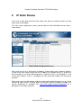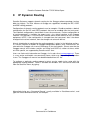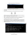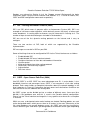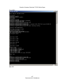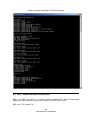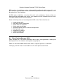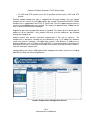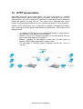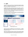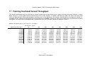
1
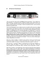
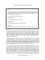
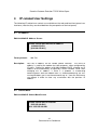
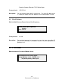
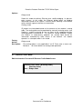
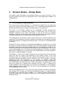
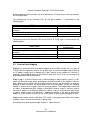
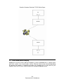
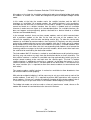
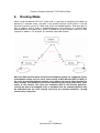
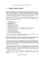
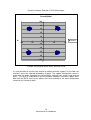
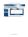
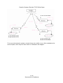
Evolution Modem TCP/IP Functionality
White Paper
P3000_REP_031 Issue 2.2, 6 January 2009
COMMERCIAL-IN-CONFIDENCE
Paradise Datacom Ltd.
Paradise Datacom LLC
1 Wheaton Road
328 Innovation Blvd.
Witham, Essex, CM8 3UJ, England.
State College, PA 16803, U.S.A.
Tel: +44(0)1376 515636
Tel: +1 814 238 3450
Fax: +44(0)1376 533764
Fax: +1 814 238 3829
http://www.paradisedata.com
Copyright © 2005-2009 Paradise Datacom Ltd. All rights reserved.
Commercial-In-Confidence
Paradise Datacom Evolution TCP/IP White Paper
Table of Contents
1
1.1
1.2
1.3
Introduction .......................................................................................................... 1-1
Scope ................................................................................................................. 1-1
References ......................................................................................................... 1-1
Glossary ............................................................................................................. 1-1
2
Ethernet Interfaces ............................................................................................... 2-1
3
Web User Interface............................................................................................... 3-1
4
IP-related User Settings ....................................................................................... 4-1
4.1
4.2
4.3
4.4
4.5
4.6
4.7
4.8
4.9
4.10
4.11
4.12
4.13
4.14
4.15
4.16
4.17
4.18
5
5.1
5.2
5.3
5.4
5.5
IP Address.......................................................................................................... 4-1
Subnet Mask ...................................................................................................... 4-1
Default Gateway ................................................................................................. 4-2
IP Traffic Mode ................................................................................................... 4-2
Ethernet Traffic Mode ......................................................................................... 4-3
Bridge Filtering ................................................................................................... 4-5
Bridge M&C Option............................................................................................. 4-6
VLAN Filtering Option ......................................................................................... 4-7
VLAN ID Option .................................................................................................. 4-8
Traffic Port IP Address........................................................................................ 4-9
Traffic Port Subnet Mask .................................................................................... 4-9
Traffic Port Default Gateway............................................................................. 4-10
Satellite Port IP Address................................................................................... 4-10
Satellite Port Subnet Mask ............................................................................... 4-11
Satellite Port Default Gateway .......................................................................... 4-11
TCP Acceleration.............................................................................................. 4-12
Default OSPF Configuration Option .................................................................. 4-13
Default RIP Configuration Option...................................................................... 4-14
Network Modes – Bridge Mode ........................................................................... 5-1
TCP Performance Enhancing Proxy ................................................................... 5-1
Point-to-Point Bridging........................................................................................ 5-2
Point-to-Multipoint Bridging................................................................................. 5-3
Brouting .............................................................................................................. 5-6
What Network Features Do I Need? ................................................................... 5-8
6
Routing Mode ....................................................................................................... 6-1
7
Modem email Function......................................................................................... 7-1
8
IP Static Routes.................................................................................................... 8-1
9
IP Dynamic Routing ............................................................................................. 9-1
ii
Commercial-In-Confidence
Paradise Datacom Evolution TCP/IP White Paper
9.1
9.2
9.3
9.4
RIP – Routing Information Protocol (2602) ......................................................... 9-5
OSPF – Open Source Path First (2604).............................................................. 9-5
BGP – Border Gateway Protocol (2605) ............................................................. 9-8
Zebra Routing Manager (2601)........................................................................... 9-9
10
Header Compression ..................................................................................... 10-1
11
Modem Web Access Over ESC Channel....................................................... 11-1
12
Quality of Service ........................................................................................... 12-1
13
HTTP Acceleration.......................................................................................... 13-1
14
IP Over ESC Channel ..................................................................................... 14-1
15
IP Data Via MultiMux ...................................................................................... 15-1
16
SNMP............................................................................................................... 16-1
17
Framing Overhead Versus Throughput ........................................................ 17-1
iii
Commercial-In-Confidence
1
Introduction
This document describes the TCP/IP capabilities of the Paradise Datacom Evolution
series of satellite modems. It should be read in conjunction with the user manual
(Reference 1).
1.1
Scope
This report documents the Evolution modem TCP/IP features and performance, including
network configurations that are supported, bridging, brouting, point-to-point operation,
point-to-multipoint operation, web user interface, header compression, TCP acceleration,
HTTP acceleration, performance, SNMP support, routing etc.
1.2
References
1. Installation and Operating Handbook for Evolution Series Satellite Modems
2. Remote M&C Specification for Evolution Series Satellite Modems
3. Quagga user manual: ‘A routing software package for TCP/IP networks’, July 2006
(available from http://www.quagga.net/docs/quagga.pdf)
1.3
Glossary
AS
BGP
EGP
IGP
OSPF
RIP
Autonomous System
Border Gateway Protocol – Dynamic EGP routing protocol
Exterior Gateway Protocol
Interior Gateway Protocol
Open Shorted Path First – Dynamic IGP routing protocol
Routing Information Protocol – Dynamic IGP routing protocol
Commercial-In-Confidence
Paradise Datacom Evolution TCP/IP White Paper
2
Ethernet Interfaces
Modem Rear Panel Showing Ethernet Connectors
There are two RJ-45 auto-sensing 10/100Mbps Ethernet connections. These support halfduplex operation as standard but can be changed to full-duplex under software control (see
Note 1). Full duplex operation requires that only one other Ethernet device is on the same
physical network segment as the modem, in order to avoid data collisions, which cannot be
detected in full duplex mode.
One of the Ethernet ports can be switched to the main modem traffic channel for sending
and receiving TCP/IP data over satellite, while the other can be used for remote M&C
(monitor and control). M&C control can be via the Simple Network Management Protocol
(SNMP), an embedded web server that sends web pages to a web browser, a Telnet-style
terminal emulation application or via TCP packets that encapsulate Paradise Universal
Protocol (PUP) commands. Although the two connectors are used for IP traffic and remote
M&C respectively, they are in fact interchangeable since the modem acts as an Ethernet
bridge (meaning satellite IP traffic and modem M&C messages can use the same single
connector if preferred). Consequently, there is no user set up, other than assigning a single
IP address, subnet mask (and, if required, a default gateway) to the modem. If required, the
Ethernet M&C port can be removed from the bridge – in this case, the two Ethernet ports
function independently of each other.
Note that an M&C IP address of 0.0.0.0 can be entered in which case Dynamic Host
Configuration Protocol (DHCP) is used to automatically get an IP address from a DHCP
server on the network. One request is made every minute until a request is successful.
Note that there is a separate IP address associated with the IP traffic port. Regardless of
any other settings, this address is used only when either the M&C port is out of the
Ethernet bridge and TCP acceleration mode is selected, or when routing mode is selected.
Note that the modem is not configured for auto-sensing the cable type and consequently
either a straight or crossover (patch) cable may be required, depending on the equipment
being connected (typically a straight cable is required when connecting direct to a PC and a
crossover cable is required when connecting to a hub or switch). (Although the modem has
the capability of auto-sensing the cable type, Paradise has found that auto-sensing is not
implemented in a standard way in all Ethernet devices and this can lead to modems and
other devices failing to talk to each other correctly, which is why Paradise does not use this
feature.)
2-1
Commercial-In-Confidence
Paradise Datacom Evolution TCP/IP White Paper
Note 1:
From software version V1.9.20, the base modem supports full duplex operation. It
will not auto-sense the duplex setting but must be manually switched with the
following Paradise Universal Protocol (PUP) commands (see Reference 2 for
information on the PUP protocol).
To set to full duplex, enter the following:
terr duplex full
To set to half duplex, enter the following:
terr duplex half
To display the current setting, enter the following:
terr duplex
After any change the modem must be rebooted for the change to take effect.
Both of the Ethernet connections form part of an Ethernet bridge. Essentially, this makes
the modem disappear from the network in relation to passing IP traffic over satellite.
Consequently, there is no user set up, other than assigning a single IP address and subnet
mask to the modem for M&C use. In addition, static routes are supported. These are
typically not required in bridging mode but are useful in other modes such routing mode or
when TCP acceleration is being used. For complex network routing requirements, an
external router may be required
The bridge has to learn what devices are on which network segment in order to avoid
creating bridging loops, where Ethernet frames circulate endlessly, using up valuable
bandwidth. The bridge therefore maintains information on how to forward frames, based on
replies that are received from each device. This learning process typically takes around 15
to 20 seconds after traffic starts to be received by the bridge. During this time, no traffic will
be passed by the bridge. It does, however, have the benefit that by learning how to forward
frames, the bridge becomes transparent, requiring virtually no user set up.
The modem software supports two basic modes of Ethernet bridge operation. Firstly, there
is a point-to-point mode for when one modem is transmitting to and receiving from one
other modem. The bridging software expects to receive replies that it uses to build up
information about what devices exist on specific network segments. Secondly, there is a
point-to-multipoint mode for when one modem is transmitting to several modems. In this
mode, the Ethernet bridge of the transmitting modem does not expect to receive replies
from the receiving modems and simply transmits all packets over satellite that are not
destined for itself. Since each modem receives all of the data, it is the user’s responsibility
to filter out any data that is not required at a particular remote location (typically using a
2-2
Commercial-In-Confidence
Paradise Datacom Evolution TCP/IP White Paper
router to do this). However, the modem supports two features that can help with this
process as described in Note 2 below.
Note 2:
VLAN Tagging
The modem supports IEEE 802.1q VLAN tags. If data is received with these tags
then the data, complete with tags, is transported transparently over satellite.
However, it is also possible for the modem to use VLAN tags over just the satellite
portion of the link to support point-to-multipoint operation where there is a return
path and VLAN tags are not already present in the data coming into the
modems. In this mode, each remote modem is assigned a unique VLAN tag
(4094 tags are available) by the user. The hub Tx modem automatically learns
what tags are being used by each remote. It also learns which devices are
connected to each remote. It then adds a VLAN tag to each incoming packet,
labeling it with the correct VLAN id for the particular remote it is destined for. At
each remote, all packets are inspected and rejected unless they contain the
relevant VLAN tag for that particular remote, thus filtering out unwanted data. This
operation is performed at a low level and is very efficient. The remotes remove the
VLAN tags for onward transmission of packets onto the local network at the
remote. VLAN tagging by the modem is supported only in point-to-multipoint mode
(selected by setting the Ethernet traffic mode to Hub or Remote as appropriate).
Brouting Filtering
When using Brouting mode to implement point-to-multipoint mode (where there is
an indirect return path) then there is a user option for the remote modem to filter
out all packets other than those intended for the modem itself and the local
network. This stops unwanted packets being proliferated onwards and creating
potential packet storms.
There is a default gateway IP address that can be set. When specified (i.e. the value is not
0.0.0.0) then the gateway provides a next-hop IP address for all destinations that are not on
the local subnet. Typically this is the address of a router that has been set up to forward
packets to the correct network. The gateway is used when the modem is not in a pure
bridging mode, e.g. when in routing mode or when performing TCP acceleration or header
compression.
TCP acceleration support is available. This uses a proprietary Performance Enhancing
Proxy (PEP) to overcome adverse performance of standard TCP caused by satellite
conditions. Elements of standard TCP operation that are significantly affected by satellite
delay include congestion avoidence control, window sizing and data acknowledgement
mechanisms, which combine to severely reduce data throughput. The PEP overcomes
these problems and allows utilization of almost all of the available bandwidth (typical
figure is around 90% bandwidth utilization). PEP performance is described in Section 5.1.
2-3
Commercial-In-Confidence
Paradise Datacom Evolution TCP/IP White Paper
In terms of UDP performance, throughput depends on the packet size being used. With
large packets of around 1500 bytes, the throughput level can be as high as 55Mbps. The
base modem will process 10000 packets per second. This equates to 5Mbps for the
smallest VOIP packets of 64bytes.
Note that the actual data throughput level always needs to be set lower than the satellite
link data rate because of TCP/IP packet header overhead. A table is shown in Appendix
A that relates the payload throughput to an overall data rate.
An optional high performance IP Traffic card (P3714) is available. When the IP Traffic
card is fitted the modem may additionally be configured to operate as a router.
.
2-4
Commercial-In-Confidence
Paradise Datacom Evolution TCP/IP White Paper
3
Web User Interface
The modem includes an embedded web server that allows full monitoring and
configuration of the modem via a web browser (available on port 80). Secure HTTP
connections can also be made via HTTPS (port 443) with the non-secure port 80 access
being disabled in this mode. Microsoft Internet Explorer V5.5 and above is supported as
standard. Paradise Datacom has a policy of avoiding the use of non-standard browser
extensions in its software wherever possible but cannot guarantee correct operation with
any other browser.
The web user interface is described in Reference 1.
3-1
Commercial-In-Confidence
Paradise Datacom Evolution TCP/IP White Paper
4
IP-related User Settings
The following IP-related user controls are available on the web and local front panel user
interfaces (note that they are described from the perspective of the front panel).
4.1
IP Address
Edit-Unit-M&C-IP Address Screen
Remote control port Ethernet IP address:
010.000.070.001
[010.000.070.001]
Factory default:
Description:
4.2
10.0.70.1
Sets the IP address for the remote control interface. The same IP
address is used by the modem for traffic purposes, when configured for
IP traffic. Setting an address of 0.0.0.0 enables DHCP, allowing an IP
address to be automatically assigned by a DHCP network server. After
changing the IP address, if there is a problem in establishing
communications with the modem then it is recommended that (for PCs
running Windows) you issue the command ‘arp –d *’ from the Start menu
run prompt in order to clear any association with the previous IP
address.
Subnet Mask
Edit-Unit-M&C-IP Subnet Mask Screen
Remote control port IP netmask:
[255.255.000.000]
New: 255.255.000.000
4-1
Commercial-In-Confidence
Paradise Datacom Evolution TCP/IP White Paper
Factory default:
Description:
4.3
255.255.0.0
Sets the remote control port IP subnet mask. The same IP subnet mask
is used by the modem for traffic purposes, when configured for IP traffic.
Default Gateway
Edit-Unit-M&C-Gateway Remote Control Port IP gateway
Remote control port IP gateway:
[0.0.0.0]
New: 0.0.0.0
Factory default:
Description:
4.4
0.0.0.0
Sets a default gateway that represents the ‘next hop’ when forwarding IP
packets from the modem. The address 0.0.0.0 is used to specify that no
gateway is set.
IP Traffic Mode
Edit-Unit-Interface-Terrestrial-IP Mode Screen
./Unit/Interface/Terrestrial/IP mode:
Change:[Bridge mode] ENTER=next
To:[Routing mode] BACK=prev
4-2
Commercial-In-Confidence
Paradise Datacom Evolution TCP/IP White Paper
Options:
Bridge mode
Select this mode for ordinary Ethernet over satellite bridging, i.e. point-topoint systems. In this mode, the Ethernet bridge builds up bridging
information based on the replies it receives back, allowing it to ascertain
which network segments devices are located on.
Routing mode
IP packets are forwarded based on the contents of the modem’s routing
table. The routing table can be populated by manually entering routes (see
Section 8 and/or by turning on one (or more) of the supported dynamic
routing protocols (see Section 6 The dynamic routing protocols enable
the modem to automatically populate the routing table based on
information forwarded by other routers in the network. The modem
operates as a two port router in this mode.
Factory
default:
Description:
4.5
Bridge mode
The routing option is only applicable if an IP Traffic card is fitted. See
Section 6 for further details on routing mode operation.
Ethernet Traffic Mode
Edit-Unit-Interface-Terrestrial-IP Ethernet Traffic Mode Screen
Ethernet traffic mode: [Brouting mode]
[Brouting mode]
New: Bridge mode
4-3
Commercial-In-Confidence
Paradise Datacom Evolution TCP/IP White Paper
Options:
Bridge mode
Select this mode for ordinary Ethernet over satellite bridging, i.e. point-topoint systems. In this mode, the Ethernet bridge builds up bridging
information based on the replies it receives back, allowing it to ascertain
which network segments devices are located on.
Hub
Sets up a modem to work as a point-to-multipoint bridge hub. All modems
at the hub site should be configured to this mode. Bridging rather than
brouting should be used in point-to-multipoint systems that have a direct
return path via satellite.
Remote
Sets up a modem to work as a point-to-multipoint remote site. All modems
connected to a point-to-multipoint bridge network that are situated at
remote sites (i.e. not on the hub) should be configured to this mode.
Header Compression
This is a bridging point-to-point mode where UDP and IP packet headers
are compressed in order to save satellite bandwidth. The bandwidth
savings depend on the particular packet sizes being used. This feature
supports header compression at terrestrial throughput rates of up to 2Mbps
via the base modem and throughput rates up to 16896kbps when the IP
Traffic card is fitted.
Mesh
The mesh mode supports networks where there is one carrier per site and
multiple Rx-only modems for receiving from other sites. It is implemented
as a variation of the point-to-multipoint bridging mode (hub operation).
Partial mesh networks are also supported.
Brouting mode
Select this mode for all point-to-multipoint or unidirectional IP systems
where there is an indirect return path (i.e. not via satellite). Both the Tx and
Rx modems should have brouting enabled. In this mode, the Ethernet
bridge in the Tx modem does not expect to receive replies and simply
transmits all Ethernet frames over satellite other than those destined for
itself.
TCP acceleration mode
This mode provides bridging of non-TCP packets combined with
acceleration of TCP packets using a Performance Enhancing Proxy (PEP)
that overcomes performance problems associated with using standard TCP
over satellite.
TCP acceleration mode + Header Compression
Only applicable if an IP traffic Interface card is fitted. This mode provides
bridging of non-TCP packets, acceleration of TCP packets and header
4-4
Commercial-In-Confidence
Paradise Datacom Evolution TCP/IP White Paper
compression.
Factory
default:
Description:
4.6
Bridge mode
This allows selection of the mode of operation of the modem Ethernet
bridge. See Section 5 for further details of bridge operation.
Bridge Filtering
Edit-Unit-Interface-Terrestrial-IP Bridge Filtering Screen
Bridge filtering:[Off]
1:Off
2:On
Options:
Off
In this mode, the bridge will forward all traffic not destined for the local
subnet to the default gateway if one has been specified. If the default
gateway is a router, then this allows the router to be set up to filter data in
whatever way is appropriate.
On
In this mode, the bridge will discard all traffic other than that destined for
the local subnet. This can be useful in preventing network loops from
occurring. A network loop can be created, for example, in a point-tomultipoint scenario where there are multiple Rx-only modems with a
common indirect return path and a default gateway is specified that causes
data not destined for a particular Rx modem to be routed out of the
gateway and back to the sender through the return path.
Factory
default:
Description:
Off
Controls whether the Ethernet bridge filters out all traffic other than for
the local subnet.
4-5
Commercial-In-Confidence
Paradise Datacom Evolution TCP/IP White Paper
4.7
Bridge M&C Option
Edit-Unit-Interface-Terrestrial-IP Bridge M&C Screen
Bridge M&C:[Off]
1:Off
2:On
Options:
Off
In this mode, the Remote M&C Ethernet interface will not be included in the
Ethernet bridge, thereby keeping IP traffic and M&C traffic separate. When
separate, the two Ethernet connectors on the base modem are no longer
interchangeable. Note that care should be taken in selecting this mode for
a remote modem – if the two cables have been mixed up then M&C
communications with the modem will be lost.
On
In this mode, the Remote M&C Ethernet interface is included in the
Ethernet bridge, thereby allowing IP traffic and M&C traffic to be via either
one cable or via two cables with them being interchangeable in relation to
the two physical Ethernet ports on the base modem.
Factory
default:
Description:
On
Controls whether the Ethernet M&C interface is included in the Ethernet
bridge or whether the Remote M&C and IP traffic interfaces are isolated
from each other.
4-6
Commercial-In-Confidence
Paradise Datacom Evolution TCP/IP White Paper
4.8
VLAN Filtering Option
Edit-Unit-Interface-Terrestrial-IP VLAN Filtering Screen
Enable VLAN filtering:[Off]
1:Off
2:On
Options:
Off
In this mode, VLAN tags are not generated or removed by the modem. This
means that no filtering of traffic based on VLAN id takes place. Since each
remote modem receives the same broadcast traffic, a device such as a
router must be present to filter out any traffic that is intended only for other
remote modems.
On
In this mode, each remote modem can be assigned a VLAN id which is
used by the Hub to tag each packet destined for any device attached to a
network off that particular remote modem. The tags are added by the Hub
Tx modem and removed by the remote modem. The remote modem uses
the tag to filter out unwanted data that has been broadcast indiscriminately
to all remote modems.
Factory
default:
Description:
Off
Controls whether VLAN tags are being used to implement point-tomultipoint filtering of traffic at remote modems to filter out unwanted
broadcast traffic. This option is only available in Hub and Remote
Ethernet traffic modes (since it is only used in point-to-multipoint mode
where there is a direct return path).
4-7
Commercial-In-Confidence
Paradise Datacom Evolution TCP/IP White Paper
4.9
VLAN ID Option
Edit-Unit-Interface-Terrestrial-IP VLAN ID Screen
VLAN ID:0 to 4094
[0000] Step 1
New: 0000
Units:
Minimum value:
Maximum value:
Step size:
Factory default:
Description:
None
0
4094
1
0
Sets a specific value of VLAN id. This is required only for remote
modems – assigning a VLAN id to a Hub modem has no effect. The
VLAN id is used to uniquely identify each remote modem. It is used to
filter wanted from unwanted IP packets in point-to-multipoint systems
where there is a direct return path and VLAN tags are not already being
used in relation to the data entering the modems from the terrestrial
network. VLAN ids of remote modems are automatically learnt by the
Hub and all traffic destined for a particular remote modem is tagged at
the Hub allowing it to filter wanted traffic. The VLAN tags are removed by
the modems prior to onward transmission.
4-8
Commercial-In-Confidence
Paradise Datacom Evolution TCP/IP White Paper
4.10 Traffic Port IP Address
Edit-Unit-Interface-Terrestrial-Traffic Port IP Address
./Terrestrial/Traffic port IP address:
Change:[000.000.000.000] ENTER=next
To:[000.000.000.000] BACK=prev
Factory default:
Description:
0.0.0.0
Sets the IP traffic address for the terrestrial interface when the modem is
in routing mode or when both the M&C port is out of the Ethernet bridge
and TCP acceleration mode is selected. In routing mode the two ports on
the IP traffic card are always bridged together and given this IP address.
4.11 Traffic Port Subnet Mask
Edit-Unit-Interface-Terrestrial-Traffic Port IP Netmask
./Terrestrial/Traffic port IP netmask:
Change:[255.255.255.255] ENTER=next
To:[255.255.255.255] BACK=prev
Factory default:
Description:
255.255.255.255
Sets the IP traffic subnet mask for the terrestrial interface when the
modem is in routing mode or when both the M&C port is out of the
Ethernet bridge and TCP acceleration mode is selected.
4-9
Commercial-In-Confidence
Paradise Datacom Evolution TCP/IP White Paper
4.12 Traffic Port Default Gateway
Edit-Unit-Interface-Terrestrial-Traffic Port IP Gateway
./Terrestrial/Traffic port IP gateway:
Change:[000.000.000.000] ENTER=next
To:[000.000.000.000] BACK=prev
Factory default:
Description:
0.0.0.0
Sets the IP traffic gateway for the terrestrial interface when the modem
is in routing mode or when both the M&C port is out of the Ethernet
bridge and TCP acceleration mode is selected.
4.13 Satellite Port IP Address
Edit-Unit-Interface-Satellite Port IP Address
./Satellite port IP address:
Change:[000.000.000.000] ENTER=next
To:[000.000.000.000] BACK=prev
Factory default:
Description:
0.0.0.0
Sets the IP traffic address for the satellite interface when the modem is
in routing mode.
4-10
Commercial-In-Confidence
Paradise Datacom Evolution TCP/IP White Paper
4.14 Satellite Port Subnet Mask
Edit-Unit-Interface-Terrestrial-Satellite Port IP Netmask
./Satellite port IP netmask:
Change:[255.255.255.255] ENTER=next
To:[255.255.255.255] BACK=prev
Factory default:
Description:
255.255.255.255
Sets the IP traffic subnet mask for the satellite interface when the
modem is in routing mode.
4.15 Satellite Port Default Gateway
Edit-Unit-Interface-Terrestrial-Satellite Port IP Gateway
./Terrestrial/Satellite port IP gateway:
Change:[000.000.000.000] ENTER=next
To:[000.000.000.000] BACK=prev
Factory default:
Description:
0.0.0.0
Sets the IP traffic gateway for the satellite interface when the modem is
in routing mode.
4-11
Commercial-In-Confidence
Paradise Datacom Evolution TCP/IP White Paper
4.16 TCP Acceleration
Edit-Unit-Interface-Terrestrial-TCP Acceleration
./Unit/Interface/Terrestrial/TCP accelaration:
Change:[No TCP acceleleration] ENTER=next
To:[No TCP accelaration]
BACK=prev
Options:
TCP acceleration mode
This mode provides routing of non-TCP packets combined with
acceleration of TCP packets using a Performance Enhancing Proxy (PEP)
that overcomes performance problems associated with using standard
TCP over satellite.
No TCP acceleration
The TCP acceleration mode is not turned on.
Factory
default:
Description:
No TCP acceleration mode
This option is available in routing mode.
4-12
Commercial-In-Confidence
Paradise Datacom Evolution TCP/IP White Paper
4.17 Default OSPF Configuration Option
Edit-Unit-Interface-Terrestrial-Enable Default OSPF Configuration
./Enable default OSPF configuration:
Change:[Disable OSPF] ENTER=next
To:[Disable OSPF] BACK=prev
Options:
Use OSPF enabled default
Turns on the OSPF dynamic routing protocol by setting a default
configuration that will be sufficient in most cases. The configuration can
be further tuned, if required, as specified in Section 9 .
Disable OSPF
The OSPF dynamic routing protocol is turned off. NOTE, this will overrite
any existing configuration, including any modified as specified above (see
Section 9 for details).
Factory
default:
Description:
Disable OSPF
This option is available in routing mode.
4-13
Commercial-In-Confidence
Paradise Datacom Evolution TCP/IP White Paper
4.18 Default RIP Configuration Option
Edit-Unit-Interface-Terrestrial-Enable Default RIP Configuration
./Enable default RIP configuration:
Change:[Disable RIP] ENTER=next
To:[Disable RIP] BACK=prev
Options:
Use RIP enabled default
Turns on the RIP dynamic routing protocol by setting a default
configuration that will be sufficient in most cases. The configuration can
be further tuned, if required, as specified in Section 9 .
Disable RIP
The RIP dynamic routing protocol is turned off. NOTE, this will overrite
any existing configuration, including any modified as specified above (see
Section 9 for details).
Factory
default:
Description:
Disable RIP
This option is available in routing mode.
4-14
Commercial-In-Confidence
Paradise Datacom Evolution TCP/IP White Paper
5
Network Modes – Bridge Mode
The network modes described in the following sections are mutually exclusive i.e. only
one of the modes can be active at a given point in time. These apply when IP Mode is set
to Bridge Mode.
5.1
TCP Performance Enhancing Proxy
TCP (Transmission Control Protocol) is a transport-level protocol that sits above the
network (IP) and data link (Ethernet MAC) levels. It is a connection-oriented protocol that
provides guaranteed end-to-end delivery of data packets in the right order.
TCP traffic in an Evolution modem can be ‘accelerated’, thereby increasing the
throughput rate that is achieved. Other formats of TCP/IP data, such as UDP (User
Datagram Protocol), do not require acceleration as they do not have any feedback
mechanisms from the receiver back to the sender and therefore do not attempt to restrict
throughput dependent on the perceived operating conditions of the link.
TCP acceleration in the Evolution modem is point-to-point only – point-to-multipoint is not
supported. TCP acceleration cannot be selected at the same time as bridging or brouting
modes.Consequently, in bridging and brouting modes, TCP traffic is not accelerated by
the modem.
Standard TCP treats any delay in receiving acknowledgements for data that is sent and
any request to retransmit data caused by bit errors in the received data as being caused
by network congestion and therefore throttles back the TCP throughput in response. For
satellite systems, which have a typical round trip time of around half a second, this results
in very low throughput rates. The actual rate is determined by the TCP buffer size and the
BER rate but is typically just a maximum of a few hundred kilobits per second, regardless
of how much satellite bandwidth is available.
This problem is solved in the Evolution modem by using a Performance Enhancing Proxy
(PEP) that splits the original TCP connection at the modem, creates a new TCP
connection across the satellite to the other modem and then again creates a new TCP
connection between the modem and the end point. One TCP connection is therefore
replaced by three TCP connections. In this situation, the modems spoof TCP
acknowledgements to the end points thereby persuading them to continue to send data.
The modem buffers the data and sends it across the satellite. The protocol that is used
across the satellite link is different from standard TCP only in that it is optimized for
satellite conditions and therefore does not suffer from the drawbacks of the congestion
control algorithm found in normal TCP. The result is that around 90% of the available
satellite bandwidth can be utilized.
Although the modified form of TCP used in the Evolution modem is backwards compatible
with standard TCP, this does not mean that one Evolution modem in a satellite link can
be replaced with a different type of modem. This is because general interoperability
aside, the satellite data is formatted as Ethernet over HDLC and other modems may use
a different format.
5-1
Commercial-In-Confidence
Paradise Datacom Evolution TCP/IP White Paper
A default gateway will have to be set up to forward the TCP data to the ‘next hop’ towards
the final destination.
The performance of the Evolution PEP on the base modem is summarized in the
following table:
PEP Feature
Base Modem Performance
Maximum throughput level
10Mbps
Maximum throughput level as a percentage of bandwidth Up to around 90%
available
Maximum number of concurrent connections
200
Ramp-up time to maximum throughput
3s to 9s
The performance of the Evolution PEP on the P3714 IP Traffic card is summarized in the
following table:
P3714 IP Traffic Card
Performance
Maximum throughput level
55Mbps
Maximum throughput level as a percentage of bandwidth Up to around 90%
available
Maximum number of concurrent connections
1000
Ramp-up time to maximum throughput
3s to 9s
PEP Feature
5.2
Point-to-Point Bridging
Bridging has the benefit that the modems appear to be invisible and will pass any type of
TCP/IP traffic transparently, with no set up other than to select the bridge mode (note that
an IP address needs to be assigned only if M&C control of the modem via Ethernet is
required). Since bridging works at the Ethernet rather than the IP level, any routing must
be provided externally to the modem.
Bridge mode is used for Ethernet over satellite bridging in point-to-point systems. In this
mode, the Ethernet bridge builds up bridging information based on the replies it receives
back, allowing it to ascertain which network segment devices are located on. In order for
bridging to work therefore, the point-to-point link must be duplex so that the sending
modem is able to receive replies from the receiving modem. The bridge tables are based
on replies to broadcasted ARP (Address Resolution Protocol) requests that are used to
translate IP addresses to Ethernet addresses. When a reply is received from a device on
a specific interface then that interface is tagged with details of the pair of Ethernet/IP
addresses. Both modems must be on the same subnet for point-to-point bridging to work..
Bridge mode should not be used when TCP traffic is being passed at data rates above
128kbps, unless external acceleration is being used.
An example of a point-to-point bridge network is shown overleaf.
5-2
Commercial-In-Confidence
Paradise Datacom Evolution TCP/IP White Paper
5.3
Point-to-Multipoint Bridging
Bridging can also be used in point-to-multipoint systems provided there is a direct return
path over satellite. One of two modes (Hub or Remote) needs to be selected depending
on whether the modem is situated at the hub or at a remote site. It is not necessary for
modems to be on the same subnet for point-to-multipoint bridging to work.
5-3
Commercial-In-Confidence
Paradise Datacom Evolution TCP/IP White Paper
All modems at the hub site should be configured to point-to-multipoint bridge hub mode.
All modems at remote sites should be configured to point-to-multipoint bridge remote
mode.
In this mode, at the hub, the modem marks the satellite interface and the M&C IP
interfaces as ‘unreliable’. At a remote modem, the satellite interface is also marked as
unreliable but the terrestrial IP interfaces are classed as reliable. If a destination device
cannot be found on a reliable interface then the data is flooded onto all unreliable
interaces in order to ensure it gets to its intended destination. On a reliable interface, this
does not happen and consequently packets destined for a device linked to a reliable
interface are forwarded directly.
In the example overleaf, there are three remote modems each of which communicates
with a particular modem at the hub. At the hub, only one of the modems has a
transmission capability, with the other two being receive only. To allow the receive-only
modems to send data to remote modems, their terrestrial IP interfaces are daisy-chained
to that of the modem with the transmission capability (with the IP traffic port of a modem
being linked to the IP M&C port of the next modem in the chain). If remote modems wish
to communicate with each other then their corresponding hub modems must forward the
incoming satellite messages to the hub transmitter modem, which sends them back over
the satellite to be received by the destination modem.
The hub modem M&C IP interface is marked as unreliable because daisychaining means
that they may not receive any reply from the destination device on those interfaces. The
hub satellite interface is marked as unreliable causing received data (which may be for
another remote modem) to be sent back over the satellite again. The hub Tx modem
satellite interface is additionally marked as a ‘repeater’ so that data that comes in via its
satellite interface, for which there is no direct path to the destination, is sent back out on
the same interface (this is required to allow two remote modems to communicate with
each other).
The remote modem satellite interface is marked as unreliable to allow broadcasts from
the remote modem to work properly.
With point-to-multipoint bridging, it will be necessary to set up a static route at each of the
remote modems if and only if it is required to perform M&C operations with respect to
those modems. If there are a number of networks hanging off the remote modems then it
is not necessary to set up static routes in the modems when bridging is being used.
The bridge hub mode can also be used as a form of ‘promiscuous’ mode, where an Rx
modem will forward all received data to the terrestrial interface.
5-4
Commercial-In-Confidence
Paradise Datacom Evolution TCP/IP White Paper
5-5
Commercial-In-Confidence
Paradise Datacom Evolution TCP/IP White Paper
5.4
Brouting
Brouting is used for point-to-multipoint or unidirectional IP systems where there is an
indirect return path (i.e. not via satellite). It provides a combination of bridging and very
simple routing. Both the Tx and Rx modems should have the brouting mode enabled. In
this mode, the Ethernet bridge in the Tx modem does not expect to receive replies and
simply transmits all Ethernet frames over satellite other than those destined for itself. In
the Rx modem, packets are passed up the TCP/IP stack to the IP layer, which decides on
how to forward them. A default gateway can be specified, which acts as a route of last
resort and individual static routes can be set up to specify where packets for specific
subnets should be forwarded to. Static routes are not required when there is only one
network on each end of the link. An example network is shown overleaf.
Filtering can be applied to discard all data not destined for the local subnet. If this is not
used, then a default gateway address of a router must be specified that is responsible for
routing all data to other networks and avoiding network loops being created where
packets circulate continuously.
Normal bridging does not work properly when there is an indirect return path because it
assumes that replies to any transmissions will be received via the same network interface
used for the transmitted data. Specifically, in relation to the diagram shown overleaf, IP
equipment plugged into a hub modem will issue ARP requests to obtain the
corresponding IP addresses. No responses to ARP requests will be received in this
situation, as there is no return path via the hub modem. This will result in IP requests
never even getting to the modem because they do not have an associated MAC address
(returned from the ARP request).
In order to get IP equipment at the hub to send traffic destined for networks 10.1.0.0/16
and 10.2.0.0/16 via the hub modem, router 10.0.0.1 in the diagram must be set to forward
traffic to the hub modem (which acts as the gateway to these networks). When this is
done, all traffic for these networks will be trusted to the hub modem and no ARP requests
need to be sent over the satellite. In fact, any ARP responses that are received over the
satellite are dropped in Brouting mode and not processed – consequently, Brouting
should never be selected when a direct rather than indirect return path is being used
because data will either not be passed at all or will stop within a short period of time.
The hub modem indiscriminantly forwards all requests through to the satellite channel. On
the remote modems, the Ethernet MAC addresses passed in data from the hub modem
will not match any device on the site. To combat this, all packets received via satellite are
passed up the IP stack to enable the IP address to be resolved to the correct MAC
address. Once these steps have been taken all packets sent to the hub with valid IP
address will be forwarded to the correct device.
5-6
Commercial-In-Confidence
Paradise Datacom Evolution TCP/IP White Paper
Care should be taken if a default gateway is specified for any modem. This is because
modems could end up forwarding all packets that are not destined for them back onto the
network, creating a storm of duplicated IP packets that will congest the network. To help
with this situation a bridge filtering option is available. When off, all traffic not destined for
the local subnet will be forwarded to the default gateway if one has been specified. If the
default gateway is a router, then this allows the router to be set up to filter data in
whatever way is appropriate. If filtering is on, then all packets not destined for the local
subnet are discarded.
5-7
Commercial-In-Confidence
Paradise Datacom Evolution TCP/IP White Paper
5.5
What Network Features Do I Need?
When deciding what modem IP features are required to support a particular network
installation, it may be useful to ask the following questions:
•
•
•
•
•
•
•
Will the TCP data rate exceed 128kbps?
o Yes. In this case it is recommended that TCP acceleration is used in order to
use the satellite bandwidth efficiently. This can either be performed by the
base modem, up to 10Mbps, or via the P3714 IP Traffic card option (up to
55Mbps) or a solution whereby the TCP data is accelerated externally to the
modem will be required. For internal acceleration, one or more TCP
acceleration SAF features are required depending on the data rate required.
o No. The TCP acceleration SAF feature is not required.
If TCP acceleration is required, is it for point-to-point operation?
o Yes. Point-to-point TCP acceleration between two Evolution modems is
supported.
o No. The modem supports only point-to-point TCP acceleration – more
complex network requirements may require acceleration to be provided
externally to the modem.
If TCP acceleration is required, will the data use IPsec encryption (typically
used to secure VPN links)?
o Yes. The modem cannot accelerate IPsec-encrypted data because the original
TCP headers are normally encrypted (tunnel mode) and IPsec headers cannot
be modified without violating authentication rules. The modem will, however,
pass IPsec data transparently.
o No. There is no issue.
Will theTCP data rate exceed 10Mbps?
o Yes. This is the maximum rate that the base modem can accelerate to and
beyond this the P3714 IP Traffic card is required (to go up to an acceleration
rate of 55Mbps).
o No. Continue to the next question.
Will the data be VoIP data or have a large number of small packet sizes (150
bytes or less)?
o Yes. UDP packets are supported at rates of up to 10000 packets per second.
This equates to 5Mbps for the smallest VOIP Ethernet frames of 64bytes and
equates to 55Mbps for the largest possible UDP packet sizes. The modem
supports higher throughput rates as the packet size increases, up to 55Mbps
of UDP data with large packet sizes (around 1500 bytes).
o No. Continue to the next question.
Is the Evolution modem required to interoperate with another type of modem in
relation to passing TCP/IP traffic?
o Yes. The Evolution modem transmits Ethernet data encapsulated within HDLC
frames, over the satellite. Even although other non-Evolution modems may be
set to use compatible forward error correction and modulation schemes as the
Evolution modem, they may not recognize the particular way in which the
TCP/IP data is being transmitted and will therefore not pass the TCP/IP data
successfully.
o No. Continue to the next question.
Does the network require point-to-point links?
5-8
Commercial-In-Confidence
Paradise Datacom Evolution TCP/IP White Paper
Yes. This is supported by the point-to-point bridge mode, which is part of the
base modem functionality.
o No. Continue to the next question.
Does the network require point-to-multipoint links?
o Yes. There are two possible solutions. Proceed to the next question.
o No. Skip the next question.
Assuming point-to-multipoint support is required, does the network include an
indirect return path (not via satellite)?
o Yes. The Brouting SAF feature is required.
o No. The point-to-multipoint bridge mode is required, which is part of the base
modem functionality.
Is more than one of the following required at the same time – TCP acceleration,
bridging and brouting?
o Yes. The modem can only be in one these modes at any one time. Networks
can be built up where different sets of modems are in different modes but
modems will only communicate successfully with other modems that are in the
same mode.
o No. There is no issue.
o
•
•
•
5-9
Commercial-In-Confidence
Paradise Datacom Evolution TCP/IP White Paper
6
Routing Mode
When using the optional P3714 IP Traffic card, it is possible to configure the modem to
operate as a two port router. One port is the satellite interface and the other is the two
terrestrial interfaces on the IP Traffic card, which are bridged together. Each port gets its
own IP address and IP traffic is forwarded based on the contents of a routing table
contained within the modem. M&C traffic is handled on the base modem and has its own
separate IP address. For example, this could be a possible network:
Note that both point-to-point and point-to-multipoint routing are supported. Pointto-multipoint routing can use either static routing or RIP (but not OSPF or BGP). In
the case of point-to-multipoint routing, each remote will receive data intended for
other remotes. Unwanted packets can be removed by specifying ‘black hole’ static
routes at the remotes that route the unwanted data to non-existent gateways,
causing the data to be dropped. If this is not done then the unwanted packets may
be forwarded onto the local network (and onto any attached networks) causing
unnecessary congestion.
6-1
Commercial-In-Confidence
Paradise Datacom Evolution TCP/IP White Paper
The Paradise Evolution Modem supports both static and dynamic configuration of routes
in to the routing table, or a combination of the two methods. Static routes are entered into
the modem as specified in Section 8
and the creation of dynamic routes is controlled
as described in Section 9 . Static routes are those that are manually entered into the
modem and don’t change whereas dynamic routes are added into the routing table by
routing protocols that can determine network topology by listening for, and sending
information to, adjacent routers.
6-2
Commercial-In-Confidence
Paradise Datacom Evolution TCP/IP White Paper
7
Modem email Function
When providing Quality of Service reports to satellite-services end users, it would be
extremely useful to be able to easily include pertinent performance information from the
modem. The modem supports this by incorporating the desired status information into
emails that can be sent anywhere – either to someone on the local network, or worldwide
if an Internet connection is available. Performance data can even be fetched over the
satellite from a remote modem and then sent by email from the local modem.
This is possible due to the modem’s built-in Simple Mail Transfer Protocol (SMTP) email
client. This may be used to send a variety of information from the modem either on
demand or at preset intervals, including:
•
•
•
•
•
•
•
•
•
•
•
•
•
Rx Eb/No values *
AUPC distant Eb/No values *
Rx power level values *
User BER values *
AUPC Tx power level values *
Modem temperature values *
Rx frequency offset values *
The contents of the system log (i.e. all noteable events that have occurred)
Current system alarms (i.e. all Unit, Tx and Rx faults and warnings)
All configuration memories
Instantaneous spectrum data
Instantaneous constellation data
Instantaneous PRBS BER test results
* Up to four week’s worth of logged performance data is stored in the modem (this is
volatile data that is lost when the modem is powered down).
Best of all, the information is sent in CSV format, which allows the data to be instantly
copied into any spreadsheet from where it can be viewed in a number of formats (e.g. as
a graph or a table) and from which a report can be generated in a few seconds.
The type of information to be sent is selected by checking the relevant check box on the
email configurator screen (see the next page). Each type of selected data is appended to
the email in separate attachment files, for convenience. In addition to sending just the
current system alarms, the modem may be requested to send all future unit faults and
warnings as and when they occur.
The modem needs to know where to send all emails in order for them to be forwarded to
individual email accounts – this is the outgoing SMTP mail server name (e.g.
smtp.yourmailserver.com). An account name and password may be necessary. Fill out
the recipient’s email address, subject (email title) and select the appropriate tick boxes
and email reporting interval as necessary.
The Reply to address field is optional and is the address used to deliver failure
notifications in the event that an email cannot be delivered to the recipient’s email
address.
7-1
Commercial-In-Confidence
Paradise Datacom Evolution TCP/IP White Paper
The email configuration screen (found under Edit-Unit-M&C-Email menu tab) is shown
below.
Email Configuration Screen
As an example of how to use email data within a spreadsheet, consider the case of
graphing constellation data. This can be done through the following steps:
•
•
•
•
•
•
•
•
•
•
•
Having set up the modem to a working state, configure the SMTP mail server and
recipient email details.
Select the Constellation data check box and click the Send email now button.
Wait for the email to be received at the recipient’s account and open it.
To import the constellation data into a spreadsheet program (Microsoft Excel is
used in this example) do the following. Double click on the email attachment
constellation.csv and open it – this should automatically start Excel (if not, save
the attachment and then open it directly from within Excel).
Within Excel, highlight the A and B columns.
Select the Chart Wizard from the toolbar (or alternatively select the Insert menu
followed by Chart).
Select XY (Scatter) as the chart type.
Select the Scatter (topmost) sub-chart type.
Select Next and then accept the defaults for Data Range and Series.
Add a chart title and X and Y titles as desired.
Select Finish and then resize the resulting graph as desired. An example of the
output is shown over the page.
7-2
Commercial-In-Confidence
Paradise Datacom Evolution TCP/IP White Paper
Constellation
100
80
60
40
20
Q
0
-100
-50
-20
Series1
0
50
100
-40
-60
-80
-100
I
Example Constellation Graph Within Microsoft Excel
It is also possible to use the email feature to request technical support. On the web user
interface, select the View tab followed by Support. The support configuration screen is
shown over the page. Complete the contact details and type your request and send the
email. The email is automatically sent to Paradise Datacom’s technical support team.
Note that the SMTP email server address has to be entered on the email configuration
screen for this function to work.
7-3
Commercial-In-Confidence
Paradise Datacom Evolution TCP/IP White Paper
Paradise Datacom Technical Customer Support Enquiry Screen
7-4
Commercial-In-Confidence
Paradise Datacom Evolution TCP/IP White Paper
8
IP Static Routes
If you wish to work with more than one subnet, the web user interface allows up to 64
static routes to be added.
The static route configuration screen (found under the Edit-Unit-Network menu tab) is
shown below.
Static Route Configuration Screen
Each route consists of a Destination IP Address, Subnet Mask and a Gateway Address.
If none of the static routes match with the IP address of a packet that has is to be sent,
then the packet is sent to the default gateway, if specifed, or else it is discarded if it is not
for the local network. There is a checkbox for each route that enables the route when
checked.
Static routes can also be entered, and the whole routing table displayed, via the Telnet
interface to Zebra when in Routing Mode (see Section 9 and the separate Quagga user
manual (Reference 3) available from http://www.quagga.net/docs/quagga.pdf for a
description of the Zebra interface).
8-1
Commercial-In-Confidence
Paradise Datacom Evolution TCP/IP White Paper
9
IP Dynamic Routing
Paradise Datacom supports dynamic routing via the Quagga software package (version
0.98.6 or higher). The IPv4 features of Quagga are supported, including the RIP, OSPF
and BGP routing protocols.
Configuration of dynamic routing protocols can be complex. Paradise provides a default
configuration for the RIP and OSPF protocols that can be enabled from the front panel.
These default configurations should work in most circumstances. Further configuration of
all routing protocols is available, for expert users, via a telnet interface to the Quagga
software. This provides a ‘Cisco IOS-like’ interface which will be familiar to users of Cisco
equipment. NOTE: If the configuration is changed from the front panel, after it has been
changed via the telnet interface, then the changes via telnet will be lost.
A basic introduction to configuring the routing protocols is given in the following sections.
It is not the intention to explain all Quagga configuration options here; instead users are
referred to the Quagga user manual (Reference 3) for these details. Please note that the
Quagga manual also includes sections on RIPng and OSPFv3, neither of these, which
are IPv6 specific, are supported by Paradise at this time.
Users can find useful information on Quagga, via its web site at www.quagga.net. There
is a very active and helpful user community forum, which may help solving configuration
issues. The Quagga user manual can be downloaded from this site.
To configure a particular routing protocol a telnet session needs to be setup with the
appropriate routing protocol. Telnet is available on Windows PCs and can be accessed
from the Start/Run menu, by typing:
Alternatively bring up a ‘Command Prompt’, usually available in ‘Start/Accessories’, and
type the Telnet command into that, for example:
9-1
Commercial-In-Confidence
Paradise Datacom Evolution TCP/IP White Paper
The IP address used can be either the modem’s traffic port or the satellite port but not the
M&C address.
The port number required represents the routing protocol that you wish to configure.
RIP
OSPF
BGP
Zebra
2602
2604
2605
2601
NOTE: For the telnet session to be successfully established routing to the modem must
already be set up correctly, including on the local machine.
Zebra is a routing manager which, perhaps most usefully, can show the current routing
table, accumulated from all routing deamons and from statically configured routes.
The default password for all of these Telnet sessions is “Paradise”.
Each routing protocol, and Zebra, has its own configuration file. By entering commands
into the Telnet session it is possible to manipulate, and manage, the configuration file.
The manual (Reference 3) lists many commands that can be typed into the telnet session
to achieve this. For example, to display the current contents of the routing table, via
Zebra, use ‘show ip route’:
9-2
Commercial-In-Confidence
Paradise Datacom Evolution TCP/IP White Paper
It is important to understand that ‘hdlc0’ is the satellite port and ‘br0’ is the two terrestrial
ports bridged together.
A very useful feature is the ability to type ‘?’ to get a list of the currently available
commands. The ‘?’ can also be used part way through typing a command to find out what
is expected next.
Like IOS, not all commands are available at the base prompt, and there is a hierarchy of
commands, these are called ‘modes’. The ‘enable’ command is the first level of these,
and is almost always needed to achieve anything useful. Other commands that change
‘modes’ are ‘configure terminal’, ‘interface <port>’ and ‘router <rip/ospf/bgp>’. The ‘exit’
command takes the current mode back down to the previous mode. For example, from an
OSPF telnet session:
9-3
Commercial-In-Confidence
Paradise Datacom Evolution TCP/IP White Paper
Executing a command successfully, in a telnet session, means that the command takes
affect immediately, but the change is not saved in the configuration file. If the IP traffic
card reboots for any reason, such as for a configuration change entered via the front
panel, then the configuration change entered in the telnet session will be lost, if it was not
saved. Use ‘write file’ to save any changes made, once you are happy with them.
9-4
Commercial-In-Confidence
Paradise Datacom Evolution TCP/IP White Paper
Readers are referred to Section 3.4 of the Quagga manual (Reference3) for basic
information about using the telnet interface and Sections 4, 5, 7 and 9 for Zebra, RIP,
OSPF and BGP configuration commands respectively.
9.1
RIP – Routing Information Protocol (2602)
RIP is an IGP, which means it operates within an Autonomous System (AS). RIP is an
example of a distance vector algorithm, which basically means that every so often each
router broadcasts its routing table to whoever may be interested in listening to it. The
number of hops to each destination gets included in the broadcast.
RIP was one of the first dynamic routing protocols on the internet and is easy to
configure.
There are two versions of RIP, both of which are supported by the Paradise
implementation.
RIP messages are carried in UDP on port 520.
Some of the things that can be configured for RIP via the Telnet interface are as follows:
9.2
Enable/disable RIP
Enable/disable RIP on an interface/network
Configure interfaces to listen but not broadcast information
Version control
What to distribute from other routing protocols
Route filters and route map support
Authentication
RIP timer values.
OSPF – Open Source Path First (2604)
Like RIP OSPF is an IGP. OSPF has some advantages over RI - it scales better, is less
bandwidth intensive and converges faster. OSPF is an example of a link state routing
protocol. Each router builds up complete information about the network topology in the
area it operates in. From this it calculates the best routes to all destinations and these are
then the entries that are added to the routing table.
An OSPF system can be divided up into a number of different areas. Area zero (0 or
0.0.0.0) is the backbone area and this is used in the Paradise default configuration.
Please use the Telnet interface to change this in any specific case where this assumption
is incorrect.
Within an area, a designated router and a backup are elected. Routing updates are sent
to the designated router, which passes them to all routers in the area. Summaries of the
link state database are passed between areas. An OSPF area can be classified as
various different types and routers get designated to be different router types depending
9-5
Commercial-In-Confidence
Paradise Datacom Evolution TCP/IP White Paper
on their location in an area. Any further technical discussion of OSPF is considered to be
beyond the scope of this simple introduction, but readers are encouraged to seek other
sources of information.
OSPF is a protocol at the same level as UDP and TCP on top of IP (it is IP protocol 89).
Some of the things that can be configured for OSPF via the Telnet interface are:
Enable/disable OSPF
Enable/disable OSPF on an interface
Enabling/disabling passive interfaces
Adjust OSPF timers/retransmit limits, etc.
Route metric manipulation
OSPF area control/configuration
Filtering
Authentication
Router priority
How to redistribute other routes.
It will probably be more efficient to use OSPF over the satellite link than RIP. If your
existing network uses RIP, you could still use OSPF over the satellite. This is because
you can enable more than one routing protocol at the same time and because Quagga
passes routes discovered from one routing protocol to others to redistribute. To do this
enable OSPF only over the satellite port, and RIP on the terrestrial ports. This then
ensure that RIP and OSPF can redistribute the others routes (which is the default
behaviour anyway). An example network might be like this.
Assuming that both RIP and OSPF have been enabled from the front panel, this section
shows you how to further tune the configuration to achieve the above. You will, of course,
need to configure the modems at both ends of the satellite link in the same way.
9-6
Commercial-In-Confidence
Paradise Datacom Evolution TCP/IP White Paper
First OSPF:
Now RIP:
9-7
Commercial-In-Confidence
Paradise Datacom Evolution TCP/IP White Paper
9.3
BGP – Border Gateway Protocol (2605)
BGP is an EGP, this means it is used to connect together ASs. Each AS connected
together by BGP would be using an IGP internally, such as OSPF or RIP.
BGP uses TCP on port 179.
9-8
Commercial-In-Confidence
Paradise Datacom Evolution TCP/IP White Paper
BGP requires all neighbour routers to be explicitly configured, which means it is not
possible for Paradise to provide a default BGP configuration. All BGP configurations can
be setup via its Telnet interface.
A BGP router establishes a session with each of its neighbours. Routes which are
advertised and exchanged have various rules applied to them to decide which of them
should be added into the local routing table.
Some of the things that can be configured for BGP via the Telnet interface are:
9.4
Enable/disable BGP
BGP route metric manipulation
Which routes to announce
Which routes to distribute
Neighbouring BGP routers and their configuration
Filtering/Route maps
Community list control
Capability negotiation
Route server control
Zebra Routing Manager (2601)
Zebra manages all of the routes discovered by the other routing protocols, adding and
deleting them from the modems routing table as appropriate.
Zebra can be used to add or delete static routes, using the ‘ip route <>’ command.
To display all of the routes in the modem use the ‘show ip route’ command.
9-9
Commercial-In-Confidence
Paradise Datacom Evolution TCP/IP White Paper
First ensure that dynamic routing is turned off over the satellite, it can still be enabled on the
terrestrial ports, then setup the static routes as indicated on the diagram.
9-10
Commercial-In-Confidence
Paradise Datacom Evolution TCP/IP White Paper
Modem A configuration:
Modem B configuration
9-11
Commercial-In-Confidence
Paradise Datacom Evolution TCP/IP White Paper
9-12
Commercial-In-Confidence
Paradise Datacom Evolution TCP/IP White Paper
10 Header Compression
IP, UDP and RTP header compression is supported in accordance with the Robust
Header Compression (ROHC) standard RFC 3095 (profiles 2 and 3). ROHC typically
reduces the 40 bytes of IP, UDP and RTP header, which is typically used with Voice over
IP data, down to between 1 and 3 bytes. Ethernet header compression is also supported
in addition and this reduces 14 bytes of Ethernet frame down to typically 1 byte. Overall
savings from compression from both types of compression (e.g. for a G.729 voice stream)
can be as high as 60%.
Effect of Robust Header Compression
Voice codecs vary in terms of payload size. G.729, for example, is a popular voice codec
that operates at 7.8kbps (i.e. 10 bytes every 10ms). It typically contains 50bytes per
packet (i.e. 40 bytes of header with 10bytes of data) but may contain 20 or 30 bytes of
data instead.
It is widely acknowledged that ROHC is the most suitable available header compression
technology for use over satellite and outperforms older technologies such as Compressed
Real Time Protocol (CRTP) and IP Header Compression (IHCP).
Note that because the header compression is applied only over the satellite portion of the
link and results in the original packets being recreated upon receipt, the compression
process is completely transparent.
It is possible to specify which data streams (routes) compression should be applied to –
see the screenshot overleaf. Each route consists of a Destination IP Address and Subnet
Mask. There is a checkbox for each route that enables the route when selected. This
allows the user to apply header compression to selected routes.
The following will be compressed when the feature is enabled:
•
•
The Ethernet header will be compressed on every frame.
IP and UDP headers will be compressed when the IP payload contains a UDP
packet. (The IP header can only be compressed when the packet contains a UDP
transport layer payload.)
10-1
Commercial-In-Confidence
Paradise Datacom Evolution TCP/IP White Paper
•
IP, UDP and RTP headers when the IP payload contains both a UDP and RTP
packet.
Ethernet header compression only is supported on the base modem. This will support
compression at a rate of at least 5000 packets per second. Ethernet/IP/UDP/RTP header
compression is supported on the P3714 IP Traffic card. This will support compression at a
rate of at least 29000 packets per second. This equates to approximately 16Mbps for the
very smallest Ethernet frames of 64bytes.
Support for ‘per route’ configuration control is included. This allows up to 32 destination IP
addresses to be specified – only packets with one of these addresses get directed
through the compressor.
Another feature that ensures maximum compression is the use of ‘contexts’. The
compression is based on sending only the differences (e.g. in IP addresses) between
successive packets. However, if multiple data streams (with different IP addresses or
different protocols such as IP/UDP and IP/UDP/RTP) are interleaved then the compressor
automatically creates a new context to handle each stream ensuring that each stream is
sent with maximum compression.
Interoperability with various GSM optimisation equipment has been successful, including
NMS AccessGate and Verso Netperformer.
Header Compression Configuration Screen
10-2
Commercial-In-Confidence
11 Modem Web Access Over ESC Channel
When a framed service is selected, it is possible to use the ESC channel to fetch web
pages from a remote modem, thereby allowing M&C control of the remote modem via
the normal web interface.
Because the ESC channel is low rate, the modem implements this feature in a very
efficient manner. Instead of fetching each entire web page, the local modem sends
commands over the ESC channel to fetch the required data, which it then populates
into a locally generated web page before sending this onto to the web browser. The
selection of Local or Remote mode is made through the toggle switch on the right
hand top corner of each web page as shown below.
Local/Remote Modem Web Interface Toggle Switch
Commercial-In-Confidence
12 Quality of Service
The modem includes support for IEEE 802.1p (priority tagging). This is a layer 2
feature that uses 8 classes of data to prioritise packets. The packets must already be
tagged at the point of entry to the modem. Priority 7 is typically used for networkcritical traffic such as dynamic routing protocol packets; priorities 5 and 6 for video and
voice, etc. The modem uses the priority tag to decide how to process each packet.
The options are:
•
•
Strict priority queuing: packets are queued for transmission based solely
on their priority – highest will always be sent first.
Fair-weighting queuing: higher priority transmitted first but lower priority
packets are given a percentage of the bandwidth to stop total starvation.
The implementation of IEEE 802.1p is as follows:
• The 8 QoS priority levels are mapped to three TCP/IP queues in the
modem.
• Packets with highest QoS priority (level 7) are sent to high priority TCP/IP
queue.
• Delay-sensitive packets (QoS levels 6 and 5) are sent to the medium
priority queue.
• The remainder (QoS levels 4 to 0) are sent to the low priority TCP/IP
queue.
• For strict priority queuing, all packets in high priority queue are processed
before any in medium priority queue which in turn are processed before
any in the low priority queue.
• For fair-weighting queuing, for every 4 packets sent from high priority
queue, 2 are sent from medium queue and 1 from low priority queue.
Commercial-In-Confidence
13 HTTP Acceleration
Web pages are made up of multiple objects, e.g. each in-line image is a separate
object. Web browsers typically fetch each in-line object sequentially, one at a time.
Some browsers will start a second TCP connection so two objects can be fetched in
parallel but typically no more than this. This means that a web page with several
images will typically take multiples times the satellite delay before it is fully displayed.
Paradise HTTP acceleration uses a ‘web proxy’ to prefetch web page inline objects
over satellite prior to them being requested by the web browser. With respect to the
diagram below:
•
•
•
•
All web page HTTP requests are intercepted by Modem 1, which performs
any necessary DNS domain name resolution.
Modem 1 passes any fetched web pages to the web browser but also
parses each web page for inline objects.
Modem 1 requests all inline objects at once from the web server via
Modem 2 BEFORE the web browser requests them.
Full web page is therefore typically displayed around 30% faster on
average.
Commercial-In-Confidence
14 IP Over ESC Channel
The Engineering Service Channel (ESC) is a low rate communications channel
separate from main data channel. It is available when a framed satellite service is
selected. Amongst other uses, it can be used for separate IP communications, e.g.
•
•
•
•
Voice-over-IP conversation
SNMP requests to remote modem
Internet access
Remote modem web page access
An example showing how the ESC channel could be used for VOIP communications
is shown below.
Points to be noted regarding IP over ESC usage are:
1. When in IP mode, the ESC channel implements Point-to-Point (PPP) protocol
over Ethernet, allowing IP traffic to be sent over what is actually a serial
interface. This introduces some overhead.
2. In IP mode, the ESC channel forms part of the modem Ethernet bridge and IP
traffic will be automatically routed over the ESC channel when required. Note
that when IP is also used as the main data channel interface then it is not
deterministic as to whether particular IP packets will be bridged over the ESC
channel or over the main data channel unless an IP card is fitted.
3. AUPC can be used at the same time provided there is sufficient ESC
bandwidth to accommodate both AUPC messages and the user IP traffic.
Commercial-In-Confidence
Evolution Modem TCP/IP Functionality White Paper
4. For very low bandwidth, it is recommended that P300 AUPC emulation mode
is used. This uses the ESC channel in serial mode rather than IP mode and
allows very efficient communication. However, user IP traffic is not supported
over the ESC channel in P300 emulation mode.
14-2
COMMERCIAL-IN-CONFIDENCE
15 IP Data Via MultiMux
The MultiMux is a feature based on the Quad E1 interface card that allows IP data to
be multiplexed with either or both serial data and E1 data and presented on a single
carrier. It can:
•
•
•
Take 1 to 3 E1s, each with Drop/Insert
Take IP traffic (specified as a multiple of 64kbps up to data rate limit of 2Mbps)
Take serial data such as V.35 (specified as a multiple of 64kbps up to data
rate limit of 2Mbps)
All of the data is multiplexed together onto the main satellite data channel and
demultiplexed at the other end of the link. It is particularly useful for transitioning GSM
systems from E1 to TCP/IP, where a hybrid solution is required involving support for
both types of data.
Commercial-In-Confidence
16 SNMP
It is possible to enable and configure the Simple Network Management Protocol
(SNMP) V1, V2C agent within the modem, through the web interface. (Note that
SNMP V3 is also supported but currently must be set up via telnet rather than through
the user interface.) SNMP is switched off by default.
An SNMP network manager is needed to communicate with the modem. The network
manager needs to understand what M&C controls the modem supports. This
information is provided via two MIBs (Management Information Bases). There is a
Paradise MIB that defines a high level set of objects such as SSPA, modem, BUC,
etc. There is also a lower level MIB that defines the specific M&C controls of the
modem. Both are required. The SNMP MIBs are provided on the modem and can be
downloaded from the web page shown below.
The SNMP facilities of the modem are documented in the ‘Remote M&C Specification
for Evolution Series Modems’. The SNMP configuration screen (found under the EditUnit-M&C-Advanced menu tab) is shown below.
SNMP Configuration Screen
A basic form of security is provided by the use of community names – if an SNMP
request is made and an incorrect community name is specified for the particular
SNMP operation, then the request is rejected. Also, requests can be limited to coming
from specific IP addresses.
SNMP traps are supported, which allows the modem to inform the network manager
when an alarm occurs. The user interface allows the entry of an IP address of the trap
server that should be notified when alarms occur in the modem. Alarm notifications
are sent only once and do not require any acknowledgement from the trap server.
Commercial-In-Confidence
Evolution Modem TCP/IP Functionality White Paper
The Paradise SNMP implementation supports HP OpenView. The choice of SNMP
network manager is left to the user. A simple free MIB browser is available from
IReasoning. This is shown below.
16-2
COMMERCIAL-IN-CONFIDENCE
Evolution Modem TCP/IP Functionality White Paper
17 Framing Overhead Versus Throughput
The relationship between data link rate and the amount of data that can be transferred for a typical framing overhead of 70 bytes is shown
below. 70 bytes is a fairly typical level of overhead when TCP or UDP headers, IP headers and Ethernet headers are taken into account but
it will vary depending on exactly what protocols are being used. In the table below, for example, 243810 bytes of user data per second (i.e.
1.95Mbps bits per second) can theoretically be transferred over a 2.048Mbps satellite link. Note that the table gives the theoretical maximum
throughput - the actual level of throughput that is achieved for UDP and TCP data is defined in Sections 2 and 5.1.
Maximum throughput (bytes/s) for header size of 70 bytes
Modem Data Rate (bit/s)
2048000
5120000
8192000
16384000
25600000
33792000
34816000
43008000
44032000
45056000
51200000
52224000
Packet Size (bytes)
50
100
106,667
150,588
266,667
376,471
426,667
602,353
853,333
1,204,706
1,333,333
1,882,353
1,760,000
2,484,706
1,813,333
2,560,000
2,240,000
3,162,353
2,293,333
3,237,647
2,346,667
3,312,941
2,666,667
3,764,706
2,720,000
3,840,000
200
189,630
474,074
758,519
1,517,037
2,370,370
3,128,889
3,223,704
3,982,222
4,077,037
4,171,852
4,740,741
4,835,556
300
207,568
518,919
830,270
1,660,541
2,594,595
3,424,865
3,528,649
4,358,919
4,462,703
4,566,486
5,189,189
5,292,973
17-1
Commercial-In-Confidence
500
224,561
561,404
898,246
1,796,491
2,807,018
3,705,263
3,817,544
4,715,789
4,828,070
4,940,351
5,614,035
5,726,316
1000
239,252
598,131
957,009
1,914,019
2,990,654
3,947,664
4,067,290
5,024,299
5,143,925
5,263,551
5,981,308
6,100,935
1200
241,890
604,724
967,559
1,935,118
3,023,622
3,991,181
4,112,126
5,079,685
5,200,630
5,321,575
6,047,244
6,168,189
1400
243,810
609,524
975,238
1,950,476
3,047,619
4,022,857
4,144,762
5,120,000
5,241,905
5,363,810
6,095,238
6,217,143