1
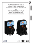
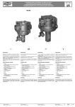
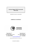
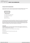
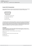
Project/product code: FM581 Description: Digital controlled DC-Motors amplifier Document type: User Manual Reference versions: Hardware FM581 100V 8A FRANCESCHI MARINA S.n.c. 200V 5A ELETTRONICA INDUSTRIALE Via Verga, 5 int.6 20842 Besana in B.za (MB), Italy Tel.0362-802070 - Fax. 0362-802648 e-mail: [email protected] – web: www.franconline.com FM581 Digital controlled DC-Motors amplifier Arosio Lorenzo User Manual FRANCESCHI MARINA S.N.C. 12/10/11 2 FM581 Digital controlled DC-Motors amplifier User Manual 12/10/11 Indice generale FM581.............................................................................................................................................1 Digital controlled DC-Motors amplifier ......................................................................................1 User Manual...............................................................................................................................1 Technical specifications.........................................................................................................4 Dimensions............................................................................................................................5 Connections...........................................................................................................................6 Digital inputs...........................................................................................................................7 LED and digital outputs..........................................................................................................8 Analog inputs.........................................................................................................................9 Jumpers description.............................................................................................................10 Modality of operation ...........................................................................................................11 Alarms..................................................................................................................................14 ModBus protocol..................................................................................................................15 Arosio Lorenzo FRANCESCHI MARINA S.N.C. 3 FM581 Digital controlled DC-Motors amplifier User Manual 12/10/11 Technical specifications Interfaces Power supply Output FM581 size => Nominal current Maximum current Peak current Protection Switching frequency PWM frequency Supply voltage (maximum) Supply voltage (minimum) • • • • • 200V 5A 8 20 28 Supply overvoltage Supply undervoltage Shortcircuit Shortcircuit to ground Power stage overheating KHz KHz 195 Vdc 20 40 Vdc Communication protocol ModBus, RTU mode Supported functions: 03h, 04h, 06h, 10h Slave address default: 1 (www.modbus.org) Digital input ● Disable counter-clockwise rotation ● Disable clockwise rotation ● General inhibit ● Curren limit / alarm (together) ● Drive inhibit / alarm (together) ● +/-10V, main speed or current reference ● Tachometer input, with automatic offset and scale (max. 29V) ● 0-10V, nominal current limitation (abs[+/-10V] ) Control loop mode Current or Current+Speed by main input reference, with variable current limit by an auxiliary reference Controller type Current loop controller: PI Speed loop controller: PID Feedback mode For speed loop Back-EMF without external connection or with DCtachometer. Offset compesation and filtering Automatic calibration of internal current and voltage offsets. Analog input low-pass filtered with configurable filter with the possibility to correct manually the offset. Working temperature Humidity (no condense) Protection class Dimensions from 0.1 to 30 s from -10 to +50 °C from 5 to 95 % IP00 100(h) x 65(l) x 39(p) mm ~0,2 Kg Weight Arosio Lorenzo A A A 100 Acceleration/Deceleration Ramps Environment 16 32 Serial port RS232 19200Kbps,8E1 Analog input Weight Dimensions 5 10 14 Control and configuration interface Digital output (open-drain, 24V 100mA) Control Loop features 100V 8A FRANCESCHI MARINA S.N.C. 4 FM581 Digital controlled DC-Motors amplifier User Manual 12/10/11 Dimensions Arosio Lorenzo FRANCESCHI MARINA S.N.C. 5 FM581 Digital controlled DC-Motors amplifier User Manual 12/10/11 Connections Connections list Connector Description 1 SpeedRef – 2 SpeedRef + 3 Tacho – 4 Tacho + 5 Ref – 6 Ref + 7 Non connected 8 Input1 9 Input2 J1 10 Input3 11 0V 12 Output1 (open-drain, 24V 100mA) 13 -12V 14 +12V 15 Input4 16 Output2 J2 (RS232) M1 (Power) Arosio Lorenzo 1 2 3 4 1 2 3 4 (open-drain, 24V 100mA) Tx Data Rx Data GND GND +V Supply M1 M2 GND Analog input, speed/current main reference (+/-10V) Tachometer input (max. 29V) Analog input, current limit (+/-10V) Clockwise rotation disable Counter-clockwise rotation disable Drive inhibit Common 0V reference for the inputs Digital output: drive inhibit / alarm Negative reference voltage for the analog inputs Positive reference voltage for the analog inputs Not used Digital output: current limit / alarm Communication port RS232: 19200,8E1 Protocol ModBus, RTU mode Slave address default: 1 Main power supply, Positive (max 100V or 200V by size) DC-Motor connection Main power supply, Ground FRANCESCHI MARINA S.N.C. 6 FM581 Digital controlled DC-Motors amplifier User Manual 12/10/11 Digital inputs Four digital inputs are available, three with and assigned function and the fourth not used. Input Description Disable CW Disable clockwise rotation, this command leaves the motor inactive, free, without ramps or braking. Disable CCW Disable counter-clockwise rotation, this command leaves the motor inactive, free, without ramps or braking. Drive inhibit This is a general inhibit signal that disable the drive. The way to stop the motor is defined from the configuration options: freee-wheel, ramp, braking... The configuration allows to setup the active logic state of the inputs. Input activation can be set to activelow (PNP mode) or active-high (NPN mode). The jumper JP3 defines the input level in floating condition, by insertion of a pull-up or a pull-down resistor. JP3 on pin 1-2: NPN mode input, setup to activate with signals that close to 0V. JP3 on pin 2-3 (default): PNP mode input, setup to activate with signals that close to +12V. For a correct operation the active level and the position of JP3 must be coherent with the way the commands operate. Arosio Lorenzo FRANCESCHI MARINA S.N.C. 7 FM581 Digital controlled DC-Motors amplifier User Manual 12/10/11 LED and digital outputs The drive has 3 LED and 2 open-drain ouputs to signal its state. The open-drain outputs are designed for a maximum load of 100mA, 24V. LED meaning: The green LED, LD3, indicates that the power supply is connected and turned on. LD3 (green) Drive disabled: motor is disabled, drive is waiting for enable command. LD2 (red) LD1 (yellow) LD3 (green) Drive enabled: motor is enabled, drive is executing motion commands. LD2 (red) LD1 (yellow) LD3 (green) Drive in current limit condition: motor is still enabled, drive is trying to execute a command but the current is over the nominal value configured. LD2 (red) LD1 (yellow) LD3 (green) LD2 (red) Drive alarm: motor is disabled because of a continued alarm condition. The drive will refuse any enabling request while the alarm is still present. The exact cause of the alarm can be verified using the ModBus. LD1 (yellow) Outputs meaning: Output Description OUT1 Active, close to 0V, when LD1 is on: drive inhibit. OUT2 Active, close to 0V, when LD2 is on: current limit condition. Arosio Lorenzo FRANCESCHI MARINA S.N.C. Together, when LD1 and LD2 are both on: alarm condition. 8 FM581 Digital controlled DC-Motors amplifier User Manual 12/10/11 Analog inputs Reference input (current or speed): From this input the drive receives the main reference setpoint for speed or current. The input signal must be between -10V and +10V. To operate with a single-ended signal place to 0V one of the poles. The drive configuration, from ModBus, allows to correct the offset and apply a low-pass filter to this input. Variable current limit input: It's possible to apply a variable current limit during the operation in speed mode. In such a situation the main reference supplies the setpoint of speed, while this auxiliary input allows to scale the limit of current regarding to the nominal value. The control loop will accelerate the motor until the demanded speed, but always with a current under the value defined instantaneously. The limited current could not be sufficient, in this case the drive maintains active the motor at the maximum allowed speed. The input signal must be between -10V and +10V. To operate with a single-ended signal place to 0V one of the poles. The drive configuration, from ModBus, allows to correct the offset of this input. Attention: the drive uses the absolute value of the input signal to scale the nominal current value: ✗ +10V is the same of 100% of the nominal current, but also -10V. ✗ 0V is the same of 0% of the nominal current. Tachometer input: In speed mode, the feedback can be gained directly from the Back-EMF, or from a tachometer connected exactly to this input. The tachometer supply a DC voltage proportional to the speed of the shaft, in order to obtain a greater precision than the BackEMF feedback. The input signal must be between -29V and +29V. The drive configuration, from ModBus, requires to indicate the voltage/speed coefficient (V/Krpm). The drive executes an automatic scaling of the input signal, based on V/Krpm and the nominal parameters, to optimize the resolution of reading. Attention: if the tachometer output exceeds the range +/-29V, it's necessary to add, in series to both input terminals, a resistance of opportune value. The maximum voltage supplied from the tachometer is given by: Vtachomax =VKrpmtacho∗Krpmmax Note that practically the maximum speed could be over the nominal value, situation in which it is Arosio Lorenzo FRANCESCHI MARINA S.N.C. 9 FM581 Digital controlled DC-Motors amplifier User Manual 12/10/11 however necessary to respect the voltage range. The next expression gives the value of the resistance: Rs= [ VKrpmtacho∗Krpmmax −29,4 ] 29,4 100000 The value of Rs is a parameter of the drive configuration. Jumpers description Jumper # JP1 JP1 + JP2 JP2 ON OFF Test (reserved!) Normal operation Test potenza (reserved!) Reset setup to default JP3 1-2 Input Pull-Up, NPN mode JP3 2-3 Input Pull-Down, PNP mode Attention: function marked as 'Test' are reserved to the factory test procedure, the improper use can seriously damage the drive and/or the motor and cause danger for the operator. Arosio Lorenzo FRANCESCHI MARINA S.N.C. 10 FM581 Digital controlled DC-Motors amplifier User Manual 12/10/11 Modality of operation The drive controls everytime the current into the motor, realizing a current-loop control. When only this type of control is active, we say that it works in 'current mode'. In addition to the current control, the drive can realize a speed-loop control. The feedback can be gained directly from the Back-EMF, or from a tachometer. We call this way of operation 'speed mode'. Into the current loop we have a PI (proportional-integral) regulator, into the speed loop a PID (proportional-integral-derivative) regulator. In order to obtain the optimal operation of the system, it's necessary to proceed to the calibration of the regulators. Current mode: In current mode the drive behaves as a variable current generator. The current that circulates in the motor is proporzional to the reference input signal: a input of 10V corresponds to the nominal current. The involved options are (make reference to the ModBus datamodel table for details): Option Description Default value Alternative values REF Reference source Main analog input RS232 / ModBus INP Commands input source Hardware digital inputs RS232 / ModBus LEV Commands active level High Low ICS Auxiliary current limit input Disabled Enabled RMP Current ramps Disabled Enabled, configurable duration Analog input Low-pass filter Cut at 1KHz Cut at 1KHz, 500Hz, 200Hz or disabled FA0 – FA1 The involved parameters are (make reference to the ModBus datamodel table for details): Name Reg. # Unit Ur 1 V /10 Ic 2 A /10 Ip 3 A /10 Accel 6 s /10 Decel 7 s /10 iPgain 17 Q15 iPgainScale 18 n iIgain 19 Q15 iIgainScale 20 n RefDig 21 Q15 VirtualInput 22 bit Attention: the drive comes with a default calibration of the PI regulator, be careful in modifing this values a little for time. An error could cause dangerous instability. Attention: it's available a software instrument, running on personal computer with RS232 connection, to make easy access to all options and parameters. It contains also some useful functions of validation. Speed mode: In speed mode the drive try to accelerate/decelerate the motor to a speed proportional to the speed setpoint. An analog input setpoint of 10V correspond to the nominal speed. Under the speed regulation the current control is however active: the drive goes in current limit when the torque remains insufficient to reach the setpoint. The limitation of the current has in first place the scope to protect the motor and the drive from the excessive heating, but also to limit the torque developed in acceleration and deceleration. Arosio Lorenzo FRANCESCHI MARINA S.N.C. 11 FM581 Digital controlled DC-Motors amplifier User Manual 12/10/11 The involved options are (make reference to the ModBus datamodel table for details): Option Description Default value Alternative values REF Reference source Main analog input RS232 / ModBus INP Commands input source Hardware digital inputs RS232 / ModBus LEV Commands active level High Low ICS Auxiliary current limit input Disabled Enabled TCF Feedback type Back-EMF Tachometer RMP Speed ramps Disabled Enabled, configurable duration FRR Braking mode No brake / free-wheel Ramp or current limit braking Analog input Low-pass filter Cut at 1KHz Cut at 1KHz, 500Hz, 200Hz or disabled Tachometer alarm Disabled Enabled: open-circuit, short-circuit or reverse connection. FA0 – FA1 TKO The involved parameters are (make reference to the ModBus datamodel table for details): Reg. # Unit Ur Name 1 V /10 Ic 2 A /10 Ip 3 A /10 SpeedRPM 4 rpm RxI 5 Ω x100 Accel 6 s /10 Decel 7 s /10 VKrpm 8 (V/Krpm) /10 Rin 9 Ω x100 sPgain 11 Q15 sPgainScale 12 n sIgain 13 Q15 sIgainScale 14 n sDgain 15 Q15 sDgainScale 16 n iPgain 17 Q15 iPgainScale 18 n iIgain 19 Q15 iIgainScale 20 n RefDig 21 Q15 VirtualInput 22 bit Attention: the drive comes with a default calibration of the PID regulator, be careful in modifing this values a little for time. An error could cause dangerous instability. Attention: it's available a software instrument, running on personal computer with RS232 connection, to make easy access to all options and parameters. It contains also some useful functions of validation. RxI compensation The RxI compensation concurs to correct the voltage fall on the series resistance of the motor, with improved performances using Back-EMF feddback. The series resistance of the motor makes that the voltage applied to the motor is lower. If the resistance is known, this effect is easy to compensate: u mot =uref mot RxI ∗I mot where: umot = voltage to the motor urefmot = reference voltage to the motor Arosio Lorenzo FRANCESCHI MARINA S.N.C. 12 FM581 Digital controlled DC-Motors amplifier User Manual 12/10/11 RxI = RxI parameter value Imot = current to the motor If “RxI” is 0 this function is disabled. Attention: the RxI compensation could cause the control to be unstable, be careful in modifing this value a little for time and test the calibration in every load condition. I2t protection In speed mode, the supplied current can be greater of the nominal value of the motor, the maximum value is fixed from the maximum current parameter. In order to avoid that the motor is overheated because of the greater current, the drive gradually reduces the current until the nomial value: I2t protection. The current limitation respects the following rule: 2 I p−I c ∗t where: Ip = maximum current Ic = nominal current t = maximum time at maximum current (2s) The drive applies the maximum current for the maximum time of 2 seconds. If the current is lower than the maximum, the time admitted for the overload increases. The current is limited gradually until it reaches the nominal value, supplied for a limitless time. Setting up the same value as nominal and maximum current, I2t protection is disabled. Arosio Lorenzo FRANCESCHI MARINA S.N.C. 13 FM581 Digital controlled DC-Motors amplifier User Manual 12/10/11 Alarms In alarm case the drive is disabled and it marks the condition with all the LED turned on. Through the ModBus connection, with the configuration software, it's possible to know in the details the alarm cause. In order to restore the operating condition, first you must remove the alarm cause and therefore to turn-off and turn-on the drive. Alarm Cause Supply voltage too high. Overvoltage Undervoltage Overcurrent Solution Use a lower voltage source. Increase the capacitor value on the The voltage grows bacause of the power supply line. braking action. Use a power supply with “braking function”. Supply voltage too low. Use an higher voltage source. Power supply capability too low. Use a 'stronger' power source. The acceleration requires a big peak Increase the capacitor value on the of current that discharge the dc-bus power supply line. capacitors. Use a smaller motor or a bigger drive. Your motor is a load too big for this (if the inductace of the motor is very drive. low, sometimes it's necessary to add an inductor in series to it). Machanical load too high. Reduce the load. Acceleration/Deceleration ramps too Increase the duration of the ramp. short. Power stage overheating The drive is too small. Use a bigger drive. Inadequate thermal dissipation. Verify the coupling of the heatsink, verify if you need a bigger heatsink. Load too high. Reduce the load. The acceleration requires a big peak of current that discharge the dc-bus Increase the duration of the ramp. capacitors. Power stage shortcircuit Tachometer anomaly Cable shortcircuit Replace the cable Motor shortcircuit Replace the motor Damaged drive Replace the drive Only with tachometer feedback and tachometer alarm enabled. Possible causes: tacho disconnected, tachometer (or cable) shortcircuit, reverse connection. Verify cable. tachometer connection and Verify the drive configuration. Verify that the tachometer is damaged. Attention: when this alarm occurs, the drive switch to Back-EMF feedback mode and disables itself as programmed by configuration (free-wheel, ramp or braking). Arosio Lorenzo FRANCESCHI MARINA S.N.C. 14 FM581 Digital controlled DC-Motors amplifier User Manual 12/10/11 ModBus protocol The RS232 port allows to configure the drive and to control it from remote. The serial communication is based on a reduced implementation of the standard ModBus protocol in RTU mode (www.modbus.org). Only a subset of function is supported: 1. the Rx/Tx buffer is only 50bytes deep, this limits the number of registers for a single transaction, not more than 10. 2. only the following standard functions are supported: Codice Funzione 03h 04h 06h 10h Nome Funzione Read Holding Registers Read Input Registers Write Single Register Write Multiple Register 3. and this user-defined function: Cod.Funzione Nome Request to send a special identification record that contains infor41h mation about hardware and firmware versions. The communication port setup is: Baudrate Byte Parity Stop 19200bps 8bit Even 1bit Attention: it's available a software instrument, running on personal computer with RS232 connection, to make easy access to all options and parameters. It contains also some useful functions of validation. Tabella dei parametri: Name Reg. # Unit Ur 1 V /10 Motor nominal voltage. Ic 2 A /10 Motor nominal current. Equal or smaller than the drive nominal current (8A or 5A). Ip 3 A /10 Maximun current allowed to the motor. Equal or smaller than the drive maximum current (20A or 10A). SpeedRPM 4 rpm Nominal speed,. Used when tachometer feedback is enabled, an analog setpoint of 10V correspond to this speed value. RxI 5 Ω x100 RxI compensation resistance. Used if Back-EMF feedback is selected. Set 0 to exclude RxI compensation function. Accel 6 s /10 Acceleration time, used only if ramps are enabled. Decel 7 s /10 Deceleration time, used only if ramps are enabled. VKrpm 8 (V/Krpm) /10 Speed to voltage coefficient for the tachometer (V/Krpm). This is the nominal transfer gain of the tacho (if you add any resistence indicate the value in reg.#9). Rin 9 Ω x100 Value of the resistence added (if necessary) to the inputs terminals of the tachomenter. ConfigFlags 10 bit-field Option flags: see the specific paragraph that follows. sPgain 11 Q15 sPgainScale 12 n Arosio Lorenzo Description Speed-loop Proportional gain (mantissa, from 0 to +1). Speed-loop Proportional gain scale factor (base 2 exponent, from -8 to +8). FRANCESCHI MARINA S.N.C. 15 FM581 Digital controlled DC-Motors amplifier Name User Manual 12/10/11 Reg. # Unit sIgain 13 Q15 sIgainScale 14 n sDgain 15 Q15 sDgainScale 16 n iPgain 17 Q15 iPgainScale 18 n iIgain 19 Q15 iIgainScale 20 n Current-loop Integral gain scale factor (base 2 exponent, from -8 to +8). Q15 Current or Speed setpoint in 16bit fractional notation. Used when the selected reference source is from ModBus. Values from -1 to +1: 0,75 (24674) is the same of an analog input of 10V. RefDig 21 Description Speed-loop Integral gain (mantissa, from 0 to +1). Speed-loop Integral gain scale factor (base 2 exponent, from -8 to +8). Speed-loop Derivative gain (mantissa, from 0 to +1). Speed-loop Derivative gain scale factor (base 2 exponent, from -8 to +8). Current-loop Proportional gain (mantissa, from 0 to +1). Current-loop Proportional gain scale factor (base 2 exponent, from -8 to +8). Current-loop Integral gain (mantissa, from 0 to +1). VirtualInput 22 bit-field Command inputs, used when the selected commands source is from ModBus. Bit meaning: bit0: disable counter-clockwise rotation bit1: disable clockwise rotation bit2: drive inhibit ScaleAnRef 29 Q15 This parameter allows to scale main analog input (speed/current reference) by a gain factor from -1 to +1. OffsetAnRef 30 Q15 This parameter allows to calibrate to zero the offset of the main analog input (speed/current reference). OffsetAnLim 31 Q15 This parameter allows to calibrate to zero the offset of the auxiliary analog input (variable current limit). The described parameters reside in the RAM of the drive, a modification can be cancelled simply by turn off the drive. Disable the drive before to modify the setup, the configuration will have effect at the next enable command. To save permanently the value of a parameter you must copy that value to the register with address reg.#EEPROM= 100 + reg.#RAM. Example: to save 2000 to the parameter SpeedRPM (reg.# RAM4) I will send 2000 to the register reg.#EPPROM= 100 + 4 = 104. The next table shows a list of readonly parameters, useful during the calibration: Name Reg. # Unit HWLimitV 200 V /10 Absolute maximum allowed voltage. u_dc_busV 205 V /10 Actual DC-Bus voltage (power supply voltage) a_MotorV 207 V /10 Back-EMF voltage i_motorA 208 A /10 Current in the motor prevFault Arosio Lorenzo 209 bit-field Description Previous alarm flags (when bit is 1): b0=Overvoltage b1=Overcurrent b2=Undervoltage b3=Overheating b4=Shortcircuit b5=Tachometer anomaly FRANCESCHI MARINA S.N.C. 16 FM581 Digital controlled DC-Motors amplifier Name Reg. # appFault User Manual 12/10/11 Unit 211 Description Present alarm flags (when bit is set to 1): b0=Overvoltage b1=Overcurrent b2=Undervoltage b3=Overheating b4=Shortcircuit b5=Tachometer anomaly bit-field About Q15 fractional rapresentation Parameters defined as Q15 are fixed-point fractional values with 15 bits after the decimal point, that rapresent numbers from -1,0 to +1,0. In order to convert a number from decimal notation to the integer value for the Q15 variable you have to multiply by 215=32768: Q15= dec 32768 dec=Q15∗32768 There are many Q15 parameters that require only positive values, like PI and PID gains. Configuration flags: The parameter “ConfigFlags” (reg.#10) contains an array of flags defining the options of the drive. It follows a detailed description of every flag: ConfigFlags [default 0000h] 15 14 13 12 11 10 9 8 7 6 5 4 3 2 1 0 X X X X FA1 FA0 MOC TKO NAC FRR RMP TCF ICS LEV INP REF Option Description REF The speed reference can be supplied through the main analog input, connected to J1 pin 1 and 2, or from serial port with ModBus using register “RegDig”. 0 => reference from analog input 1 => reference from ModBus INP The commands inputs can be supplied from the hardware inputs, connected to J1, or from serial port with ModBus using register “VirtualInput”. 0 => hardware inputs 1 => commands from ModBus LEV By default the input are configured as active-high, this option allows to change the active level: 0 => active-high inputs 1 => active-low inputs Attention to the position of JP3 for the insertion of pull-up or pull-down on the input. ICS By default the nominal and peak motor currents are defined by registers “Ic” (reg.#2) and “Ip” (reg.#3). This option enables the auxiliary analog input, connected to J1 pin 5 and 6, in order to introduce a variable current limit. In such a case the drive ignores the peak current “Ip” because the motor current will be always limited to a fraction of “Ic” (nominal current), scaled through the analog input where +/10V=100% and 0V=0%. 0 => “Ic” + “Ip” without variable current limit 1 => “Ic” + with variable current limit TCF In speed mode it's possible to select the Back-EMF feedback or the tachometer feedback (connected to J1 pin 3 and 4). 0 => Back-EMF feedback 1 => tachometer feedback Arosio Lorenzo FRANCESCHI MARINA S.N.C. 17 FM581 Digital controlled DC-Motors amplifier User Manual 12/10/11 Option Description RMP Speed mode control and current mode control follow istantaneously every variation of the setpoint. This option introduce the insertion of increment and decrement ramps between the setpoint and the reference of the control loop. In current mode ramps are of current, in speed mode are of speed; in booth cases the registers “Accel” and “Decel” contains the duration time of the ramp, starting from 0 up to 100% (viceversa for deceleration). 0 => ramps disabled 1 => ramps enabled FRR At the general inhibit signal the drive can stop the motor in several ways, selected from this option and the RMP. 0 => no brake, free-wheel stop 1 => ramp (RMP enabled) or braking with current limit for a maximum of 2 seconds of time (RMP disabled). NAC At the startup, the drive executes a procedure of automatic calibration of the analog inputs of current and voltage of the motor. If this happens while the shaft is completely stopped there is no problem, but if the there is the possibility that the shaft is moving, it's necessary to disable the auto-calibration, exactly with this option. 0 => analog input auto-calibration enabled 1 => analog input auto-calibration disabled TKO In speed mode with tachometer feedback, this option enables and disabled the alarm for a tacho anomaly. Tachometer alarm identifies the following cases: tacho disconnected, tachometer (or cable) shortcircuit, reverse connection. 0 => alarm disabled 1 => alarm enabled MOC Select the modality of operation, current or speed: 0 => speed mode 1 => current mode FA1 FA0 Frequenza di taglio 0 0 1KHz 0 1 500Hz 1 0 200Hz 1 1 disabled This two bits select the cut frequency of the filter applied to the main analog input, or disable the filter. ______ Arosio Lorenzo FRANCESCHI MARINA S.N.C. 18