1
1.
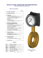
These threaded and wafer style flowmeters measure flow rate by sensing the
pressure differential created across the flow nozzle which is machined into the
body of the flowmeter. A pair of matched, opposed bellows sense the differential
pressure and drive a mechanical linkage to indicate flow rate directly on the dial.
(When fitted with a blind transmitter or digital display readout, the bellows and
mechanical linkage are replaced with a solid state differential pressure sensor).
Principle
of
Operation
2.
Installation
Planning
and Site
Selection
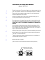
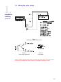
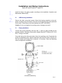
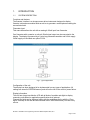
Select a site which is convenient for viewing and which provides service access to
the front and rear of the flowmeter. Note that the dial can be ordered in any
orientation at 90 degree increments and can be easily re-oriented in the field. See
Changing
!
the Dial Orientation "
in the installation section. The site selected should
provide at least 10 pipe diameters of straight meter size pipe between the flow
meter inlet and any upstream fitting such as elbow, tee or valves. There are no
special requirements for the downstream connections to the meter.
Note that the flow meters are calibrated based on schedule 40 pipe connections.
Tubing and hoses do not have the same ID as pipe and should be transitioned to
pipe at least 10 pipe diameter upstream of the flowmeter to achieve rated
accuracy.
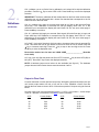
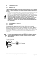
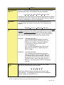
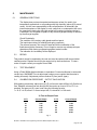
Installation Conditions
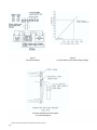
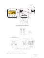
Figure 2
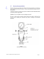
Avoid placing the flow meter where it will be subjected to water hammer and
mount the flowmeter rigidly to minimize shock or vibration.
Flow meters installed outdoors or exposed to splashing liquids should be ordered
with a gasketed case.
Protect from freezing liquids.
Page 2