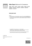
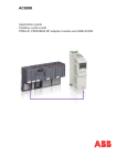
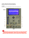
1
ACS850
Quick Start-up Guide
Standard Control Program
English . . . . . . . . . . . . . . . 3
3AUA0000045498 REV A
Effective: 3.4.2009
© 2009 ABB Oy.
All rights reserved.
ACS850 drive manuals
DRIVE HARDWARE MANUAL*
ACS850-04 Drive Modules (1.1 to 45 kW) Hardware Manual – 3AUA0000045496 (English)
ACS850-04 Drive Modules (55 to 160 kW, 75 to 200 hp) Hardware Manual – 3AUA0000045487 (English)
ACS850-04 Drive Modules (200 to 500 kW, 250 to 600 hp) Hardware Manual – 3AUA0000026234 (English)
DRIVE FIRMWARE MANUALS
ACS850 Standard Control Program Firmware Manual – 3AUA0000045497 (English).
OPTION MANUALS
ACS850 Control Panel User’s Guide – 3AUA0000050277 (English)
FIO-01 Digital I/O Extension User’s Manual* – 3AFE68784921 (English)
FIO-11 Analog I/O Extension User’s Manual* – 3AFE68784930 (English)
FIO-21 Analog I/O Extension User’s Manual* – 3AUA0000031061 (English)
FEN-01 TTL Encoder Interface User’s Manual* – 3AFE68784603 (English)
FEN-11 Absolute Encoder Interface User’s Manual* – 3AFE68784841 (English)
FEN-21 Resolver Interface User’s Manual* – 3AFE68784859 (English)
FEN-31 HTL Encoder Interface User’s Manual* – 3AUA0000031044 (English)
*A multilingual quick installation guide is included with the delivery.
Quick Start-up Guide for ACS850 with Standard Control Program 3
Quick Start-up Guide for ACS850 with Standard
Control Program
About this guide
This guide contains the basic procedure that needs to be followed to start up an
ACS850 drive (with Standard Control Program). During the procedure, the drive is set
up using the ACS850 Control Panel.
Note: Only the functions of the Control Panel needed during the procedure are
described in the guide. For further information, refer to ACS850 Control Panel User’s
Guide (3AUA0000050277 [English]).
Safety instructions
WARNING! All electrical installation and maintenance work on the drive
should be carried out by qualified electricians only.
Never work on the drive, the braking chopper circuit, the motor cable or the motor
when input power is applied to the drive. Always ensure by measuring that no voltage
is actually present.
4 Quick Start-up Guide for ACS850 with Standard Control Program
Start-up procedure
Safety
The start-up may only be carried out by a qualified electrician.
The safety instructions must be followed during the start-up procedure. See the
safety instructions on the first pages of the appropriate hardware manual.
Check the installation. See the installation checklist in the appropriate hardware
manual.
Check that the starting of the motor does not cause any danger.
De-couple the driven machine if
• there is a risk of damage in case of an incorrect direction of rotation, or
• a normal ID run is required during the drive start-up, when the load torque is higher
than 20% or the machinery is not able to withstand the nominal torque transient
during the ID run.
Power-up, control panel basics
Connect the control panel to the drive using an
appropriate Category 5E cable.
Power up the drive. After a few moments, the panel
shows the Output mode (right).
Note: The Output mode display will alternate with
“Alarm 2021 NO MOTOR DATA” until an assistant is
launched later in the procedure.
Switch to local control to ensure that external control
is disabled by pressing the LOC
REM key on the control
panel. Local control is indicated by the text “LOC” on
the top row on the display.
The two boxes on the bottom row of the display
indicate the function of the two soft keys
and
. The contents of the boxes depend on the
visible menu choices.
Press
(MENU) to access the Main menu.
Within any menu, the desired selection is
highlighted. Press the
and
keys to
make a new choice; activate by pressing
(ENTER).
The Main menu is the starting point for the
procedures described below.
REM
DIR
LOC
DIR
LOC
0.00rpm
0. 00
0. 00
0.0
Hz
A
%
MENU
0.00rpm
0. 00
0. 00
0.0
Hz
A
%
MENU
MAIN MENU
1
PARAMETERS
ASSISTANTS
CHANGED PAR
EXIT
ENTER
Adjusting parameter values
Notes:
• At any point, press
(CANCEL or EXIT) to return to the previous level.
• By default, not all parameters are visible. Set parameter 16.15 Menu set sel to Load
long to make all parameters visible.
Quick Start-up Guide for ACS850 with Standard Control Program 5
To adjust a parameter within an assistant:
• Use the
and
keys to adjust the setting. Press SAVE to accept the
setting shown and to proceed to the next parameter.
To adjust a parameter at any other time:
• In the Main menu, highlight PARAMETERS and press
(ENTER).
• Use
and
to browse the list of parameter groups. Highlight the desired
group and press
(SEL) to display the parameters within that group.
• Highlight a parameter and press
(EDIT) to adjust the setting.
• Use
and
to adjust the setting. Press SAVE to accept the setting
shown. Press EXIT twice to return to the Main menu.
Notes for more complicated edits:
• With parameters that define a digital source, the setting Const can be used to fix the
value to constant 1 (C.TRUE) or 0 (C.FALSE).
• With parameters that define an analog or digital source, the setting Pointer can be
used to freely choose any parameter value (analog) or a specific bit of a packed
boolean parameter (digital) as the source:
• With an analog source, the parameter group
and parameter index are specified. After
selecting the group, press NEXT to move to the
index setting.
The text below the cursor reflects the current
setting.
After setting the index, press SAVE to accept
the value. Press CANCEL at any point to
discard any changes and to return to the
parameter list.
LOC
• With a digital source, the parameter group,
parameter index, and bit number are specified.
After setting an item, press NEXT to move to
the next.
LOC
The text below the cursor reflects the current
setting.
After the bit number is set, press SAVE to
accept the value. Press CANCEL at any point
to discard any changes and to return to the
parameter list.
PAR EDIT
1501 AO1 src
P.01.06
0106 Motor torque
CANCEL
SAVE
PAR EDIT
1002 Ext1 start in1
P.02.01.00
0201 DI status
CANCEL
NEXT
Changing the language
By default, the language of the text shown is English. If desired, the language can be
changed as follows.
In the Main menu, make sure PARAMETERS is
highlighted, and press ENTER.
LOC
MAIN MENU
1
PARAMETERS
ASSISTANTS
CHANGED PAR
EXIT
ENTER
6 Quick Start-up Guide for ACS850 with Standard Control Program
Navigate to parameter group 99 Start-up data and
press SEL. Note that the list will wrap around in
either direction between groups 99 and 01 – it is
quicker to press
for group 99.
Make sure parameter “9901 Language” is
highlighted and press EDIT.
Select the desired language and press SAVE.
Press EXIT twice to return to the Main menu.
LOC
PAR GROUPS
99
99 Start-up data
01 Actual values
02 I/O values
03 Control values
04 Appl values
SEL
EXIT
LOC
PARAMETERS
9901 Language
English
9904 Motor type
9905 Motor ctrl mode
9906 Mot nom current
EXIT
EDIT
LOC
PAR EDIT
9901 Language
Deutsch
[0407 hex]
CANCEL
SAVE
Firmware assistants
The start-up procedures described below make use of firmware assistants. These are
routines that guide the user through the essential parameter settings.
1 – Application macro selection
In the Main menu, highlight ASSISTANTS and press
ENTER.
Highlight Firmware assistants and press SEL.
Highlight Application Macro and press OK.
LOC
MAIN MENU
1
PARAMETERS
ASSISTANTS
CHANGED PAR
EXIT
ENTER
LOC
ASSISTANTS
1
Firmware assistants
Application assistant
EXIT
SEL
LOC
CHOICE
Select assistant
Application Macro
Motor Set-up
EXIT
OK
Quick Start-up Guide for ACS850 with Standard Control Program 7
Application macros are pre-defined parameter
settings that can be used as a basis for user
applications. The following macros are available:
• Factory (for speed control applications where a
simple start/stop interface is required)
• Hand/Auto (for speed control applications where
two external control devices are used)
Parameter defaults for the macro
are applied.
• PID control (for process control applications
such as closed-loop pressure, level or flow control
systems)
• Torque control (for torque and/or speed control
of motor)
• Sequential control (for speed control
applications in which multiple constant speeds
and acceleration/deceleration ramps are needed
and are sequenced).
More information on the macros is available in the
Firmware Manual.
Highlight one of the macros and press OK.
After the text “Done OK” appears on the control panel, press OK to complete the
firmware assistant.
2 – Motor set-up
Ensure you have the motor nameplate and encoder data (if needed) at hand.
In the Main menu, highlight ASSISTANTS and press
ENTER.
Highlight Firmware assistants and press SEL.
Highlight Motor Set-up and press OK.
The assistant will guide you through the motor setup.
LOC
MAIN MENU
PARAMETERS
ASSISTANTS
CHANGED PAR
EXIT
ENTER
LOC
ASSISTANTS
1
Firmware assistants
Application assistant
EXIT
SEL
LOC
CHOICE
Select assistant
Application Macro
Motor Set-up
EXIT
Select the motor type, AM (asynchronous squirrel
cage AC motor) or PMSM (permanent magnet
synchronous motor).
1
99.04 Motor type
OK
8 Quick Start-up Guide for ACS850 with Standard Control Program
Select the motor control mode. DTC is suitable for
most cases.
Scalar mode is recommended if
99.05 Motor ctrl mode
• the nominal current of the motor is less than 1/6
of the nominal current of the drive,
• the drive is used for test purposes with no motor
connected, or
• the drive controls multiple motors and the number
of motors connected is variable.
Enter the motor data from the motor nameplate.
Asynchronous motor nameplate example:
ABB Motors
3
motor
V
690 Y
400 D
660 Y
380 D
415 D
440 D
Cat. no
M2AA 200 MLA 4
IEC 200 M/L 55
No
Ins.cl. F
IP 55
Hz
kW
r/min
A
cos
IA/IN t E/s
30
1475 32.5 0.83
50
56
50
0.83
1475
30
50
0.83
1470
34
30
30
0.83
1470
59
50
1475
50
0.83
54
30
35 1770
0.83
59
60
3GAA 202 001 - ADA
6312/C3
6210/C3
Note: Set the motor data to
exactly the same value as on the
motor nameplate. For example, if
the motor nominal speed is 1470
rpm on the nameplate, setting the
value of parameter 99.09 Mot
nom speed to 1500 rpm results in
incorrect operation of the drive.
If D (delta) data is chosen, then
connect the motor in delta.
If Y (star) data is selected, then
connect the motor in star.
180
IEC 34-1
Permanent magnet motor nameplate example:
ABB Motors
3 ~ motor
M2BJ 280SMB 10 B3
S1 SPEC INSUL.
JK-21640-1
No 3424522
Ins.cl. F
IP 55
V
Hz
kW
r/min
A
cos M IA/IN
400 D
50
55
600
103
0.97
Prod. code
6316/C3
t
E/s
2GBJ285220-ADA405445477
6316/C3
630kg
IEC 34-1
• motor nominal current
Allowed range: approximately 1/6 × I2n … 2 × I2n of
the drive (0…2 × I2nd if parameter 99.05 Motor ctrl
mode = Scalar).
99.06 Mot nom current
Quick Start-up Guide for ACS850 with Standard Control Program 9
• motor nominal voltage
99.07 Mot nom voltage
Allowed range: 1/6 × UN … 2 × UN of the drive. (UN
refers to the highest voltage in each nominal voltage
range).
With permanent magnet motors, the nominal
voltage is the BackEMF voltage (at motor nominal
speed). If the voltage is given as voltage per rpm,
e.g. 60 V per 1000 rpm, the voltage for 3000 rpm
nominal speed is 3 × 60 V = 180 V.
Note that the nominal voltage is not equal to the
equivalent DC motor voltage (E.D.C.M.) value given
by some motor manufacturers. The nominal voltage
can be calculated by dividing the E.D.C.M. voltage
by 1.7 (= square root of 3).
• motor nominal frequency
99.08 Mot nom freq
With permanent magnet motor: If the frequency is
not given on the motor nameplate, it has to be
calculated using the following formula:
f = n × p / 60
where p = number of pole pairs, n = motor nominal
speed.
• motor nominal speed
99.09 Mot nom speed
• motor nominal power
99.10 Mot nom power
The following motor data parameters can be set to improve control accuracy. If not
known, set the values to 0.
• motor nominal cosϕ (not applicable for permanent 99.11 Mot nom cosfii
magnet motors)
• motor nominal shaft torque
99.12 Mot nom torque
The following parameters define operation limits to protect the driven equipment.
• maximum speed
20.01 Maximum speed
This value should be higher than 55% of the motor
nominal speed defined earlier.
• minimum speed
This value should be less than or equal to 0 rpm.
20.02 Minimum speed
• maximum current
This value should be equal to or higher than the
motor nominal current defined earlier.
20.05 Maximum current
• maximum torque
20.07 Maximum torque1
This value should be at least 100% of motor nominal
torque defined earlier.
• minimum torque
20.08 Minimum torque1
10 Quick Start-up Guide for ACS850 with Standard Control Program
The question “Do you want to perform id-run now?” is displayed. The ID run
(identification run) will identify the characteristics of the motor for optimum control.
If you do not wish to perform the ID run at this point, select No to complete the Motor
Set-up firmware assistant. Proceed to section 3 – Start/Stop configuration.
If you wish to perform the ID run, continue with the following steps BEFORE selecting
Yes.
WARNING! With Normal or Reduced ID run the motor will run at up to
approximately 50…100% of the nominal speed during the ID run. ENSURE
THAT IT IS SAFE TO RUN THE MOTOR BEFORE PERFORMING THE ID
RUN!
Check the direction of rotation of the motor. During
the run (Normal or Reduced), the motor will rotate in
the forward direction.
When drive output phases
U2, V2 and W2 are connected to the corresponding motor terminals:
forward
direction
reverse
direction
Ensure the Safe Torque Off and emergency stop
circuits (if present) are closed.
Select Yes and press OK.
Select the ID run method.
The ID run will be performed at the next start of the
drive.
NORMAL ID run should be selected whenever
possible.
Note: The driven machinery must be de-coupled
from the motor with Normal ID run:
• if the load torque is higher than 20%, or
• if the machinery is not able to withstand the
nominal torque transient during the ID run.
The REDUCED ID run should be selected instead of
the Normal ID run if the mechanical losses are
higher than 20%, i.e. the motor cannot be
de-coupled from the driven equipment, or full flux is
required to keep the motor brake open (conical
motor).
99.13 Idrun mode
Quick Start-up Guide for ACS850 with Standard Control Program 11
The STANDSTILL ID run should be selected only if
the Normal or Reduced ID run is not possible due to
the restrictions caused by the connected mechanics
(e.g. with lift or crane applications).
Notes:
• The motor shaft must NOT be locked and the load
torque must be < 20% during Normal or Reduced
ID run. With permanent magnet motor this
restriction also applies when Standstill ID run is
selected.
• Mechanical brake is not opened by the logic for
the ID run.
• The ID run cannot be performed if parameter
99.05 Motor ctrl mode = Scalar.
Start the motor (by pressing the START button) to
activate the ID run.
ID run is indicated by alarm ID-RUN on the panel
display.
Alarm: ID-RUN
The 7-segment display on the drive will flash the
alarm code A-2008 (ID-RUN) while the ID run is in
progress. After the ID run, the display will return to
the “drive stopped” state.
After the text “Done OK” appears on the control panel, press OK to complete the
firmware assistant.
3 – Start/Stop configuration
In the Main menu, highlight ASSISTANTS and press
ENTER.
Highlight Firmware assistants and press SEL.
Highlight Start/Stop Control and press OK.
The following parameters will be set.
Note: Depending on the selections you make, the
routine may skip some of the parameters listed
below.
LOC
MAIN MENU
1
PARAMETERS
ASSISTANTS
CHANGED PAR
EXIT
ENTER
LOC
ASSISTANTS
1
Firmware assistants
Application assistant
EXIT
SEL
LOC
CHOICE
Select assistant
Motor Set-upMotor
Start/Stop Control
EXIT
OK
12 Quick Start-up Guide for ACS850 with Standard Control Program
Select the start/stop function and signal sources for
external control location 1 (EXT1). First, program
parameter 10.01 (start function), then 10.02 and
10.03 to choose the sources of the start signal.
10.01 Ext1 start func
10.02 Ext1 start in1
10.03 Ext1 start in2
The choices for parameter 10.01 are:
In1: The signal defined in parameter 10.02 is the
source for the start signal (0 = Stop, 1 = Start).
3-wire: Start/Stop commands are determined on the
basis of the two sources selected by parameters
10.02 and 10.03.
State of source 1
(via par. 10.02)
0 -> 1
Any
Any
State of source 2
(via par. 10.03)
1
1 -> 0
0
Command
Start
Stop
Stop
In1F In2R: The signal defined in parameter 10.02
starts the drive in the forward direction, and the
signal defined in 10.03 will start the drive in reverse.
In1St In2Dir: The signal defined in parameter 10.01
will start the drive (0 = Stop, 1 = Start). The signal
defined in 10.03 will change the motor direction
(0 = forward, 1 = reverse).
Select the start/stop function and signal sources for
external control location 2 (EXT2).
The selections are as with EXT1 above.
10.04 Ext2 start func
10.05 Ext2 start in1
10.06 Ext2 start in2
Define the signal source to switch between external
control locations EXT1 and EXT2 (0 = EXT1, 1 =
EXT2).
12.01 Ext1/Ext2 sel
Select the motor start function.
11.01 Start mode
Automatic is the best all-round setting that also
enables flying start (starting when the motor is
rotating).
Fast involves pre-magnetization of the motor and
should be selected if a high break-away torque is
required.
Const time should be selected if a constant premagnetization time is required. The time is set by
parameter 11.02 DC-magn time.
Select the stop mode.
Coast: The power to the motor is cut off. The motor
is left to coast to a stop.
Ramp: The motor is stopped by decelerating along
the active deceleration ramp (to be defined later).
11.03 Stop mode
Quick Start-up Guide for ACS850 with Standard Control Program 13
Select the source of the run enable signal.
10.11 Run enable
If the signal is switched off, the drive will not start, or
coasts to stop if running. 1 = Run enable signal on.
Select the source of the emergency stop OFF3
signal.
10.13 Em stop off3
If the signal is removed (in other words, changes to
0), the drive will stop along the emergency stop
ramp (defined by parameter 22.12 Em stop time).
After the text “Done OK” appears on the control panel, press OK to complete the
firmware assistant.
4 – Reference selection
In the Main menu, highlight ASSISTANTS and press
ENTER.
LOC
MAIN MENU
1
PARAMETERS
ASSISTANTS
CHANGED PAR
Highlight Firmware assistants and press SEL.
EXIT
ENTER
LOC
ASSISTANTS
1
Firmware assistants
Application assistant
Highlight Reference select and press OK.
The following parameters will be set.
SEL
EXIT
LOC
CHOICE
Select assistant
Start/Stop Control
Reference select
Note: Depending on the selections you make, the
routine may skip some of the parameters listed
below.
Select the control mode for external control
locations EXT1 and EXT2.
Speed: Speed control.
Torque: Torque control.
Min, Max, Add: Torque reference and speed
controller output are compared and the
mathematical function is applied (smaller, greater,
addition).
Depending on the selections, the speed or torque
reference source (or both) is defined next.
EXIT
12.03 Ext1 ctrl mode
12.05 Ext2 ctrl mode
OK
14 Quick Start-up Guide for ACS850 with Standard Control Program
Speed reference set-up
Choose the number of constant speeds (if any) to use.
If you select any constant speeds, you are asked if the start direction should affect the
constant speed direction.
No: The sign of the constant speed directly determines the running direction when the
constant speed is activated.
Yes: The sign of the constant speed is multiplied by the value of the Direction signal to
determine the running direction when the constant speed is activated.
You are now asked if each constant speed selector should activate one constant speed.
No: Constant speeds 1…7 are activated by the sources selected by parameters 26.02,
26.03 and 26.04 as follows:
Source defined by Source defined by Source defined by
par. 26.02
par. 26.03
par. 26.04
0
0
0
1
0
0
0
1
0
1
1
0
0
0
1
1
0
1
0
1
1
1
1
1
Constant speed active
None
Constant speed 1
Constant speed 2
Constant speed 3
Constant speed 4
Constant speed 5
Constant speed 6
Constant speed 7
Yes: Constant speeds 1…3 are activated by the sources selected by parameters 26.02,
26.03 and 26.04 respectively.
Set the constant speed selector sources.
26.02 Const speed sel1
26.03 Const speed sel2
26.04 Const speed sel3
Enter the constant speeds.
26.06 Const speed1…
Select the source of the speed reference signal.
21.01 Speed ref1 sel
21.09 SpeedRef min abs
Define the absolute minimum limit for the speed
reference. This limit applies for both the positive and
negative ranges.
Quick Start-up Guide for ACS850 with Standard Control Program 15
Define the speed scaling used for the acceleration/
deceleration times. Define the acceleration/
deceleration times.
The diagram below shows the effect of parameter
19.01 Speed scaling on the acceleration/
deceleration times.
19.01 Speed scaling
22.02 Acc time1
22.04 Acc time2
22.03 Dec time1
22.05 Dec time2
Speed
19.01
Acc.
Dec.
22.02 or
22.04
22.03 or
22.05
0
Time
Note: Acceleration/deceleration times may be
automatically extended by the existing torque limits.
Select the source to switch between acceleration/
deceleration ramp pairs 1 and 2.
22.01 Acc/Dec sel
0 = Acceleration time 1/Deceleration time 1 are in
force, 1 = Acceleration time 2/Deceleration time 2
are in force.
Torque reference set-up
Select the source of the torque reference signal.
24.01 Torq ref1 sel
Define the maximum and minimum torque
references.
24.03 Maximum torq ref
24.04 Minimum torq ref
Define the times for the torque reference to increase 24.06 Torq ramp up
24.07 Torq ramp down
from zero to nominal motor torque (ramp up) and
vice versa (ramp down).
16 Quick Start-up Guide for ACS850 with Standard Control Program
Analog input AI1/AI2 set-up (if either is selected as speed or torque reference source)
Define the filter time constant for the analog input.
%
13.01 AI1 filt time or
13.06 AI2 filt time
Unfiltered signal
100
63
Filtered signal
t
T
O = I × (1 - e-t/T)
I = filter input (step)
O = filter output
t = time
T = filter time constant
Define the maximum and minimum values for the
analog input.
13.02 AI1 max or
13.07 AI2 max
13.03 AI1 min or
13.08 AI2 min
Define the scaled values that correspond to the
maximum and minimum values defined at the
previous step. This is useful if full speed is required
at lower analog input values.
13.04 AI1 max scale or
13.09 AI2 max scale
13.05 AI1 min scale or
13.10 AI2 min scale
AI (scaled)
13.04/13.09
AI (mA/V)
13.03/13.08
13.02/13.07
13.05/13.10
After the text “Done OK” appears on the control panel, press OK to complete the
firmware assistant and the start-up procedure.
Further information
Product and service inquiries
Address any inquiries about the product to your local ABB representative, quoting the
type designation and serial number of the unit in question. A listing of ABB sales,
support and service contacts can be found by navigating to www.abb.com/drives and
selecting Sales, Support and Service network.
Product training
For information on ABB product training, navigate to www.abb.com/drives and select
Training courses.
Providing feedback on ABB Drives manuals
Your comments on our manuals are welcome. Go to www.abb.com/drives and select
Document Library – Manuals feedback form (LV AC drives).
Document library on the Internet
You can find manuals and other product documents in PDF format on the Internet. Go
to www.abb.com/drives and select Document Library. You can browse the library or
enter selection criteria, for example a document code, in the search field.
3AUA0000045498 REV A / EN
EFFECTIVE: 3.4.2009
ABB Oy
AC Drives
P.O. Box 184
FI-00381 HELSINKI
FINLAND
Telephone +358 10 22 11
Fax
+358 10 22 22681
Internet
http://www.abb.com
ABB Inc.
Automation Technologies
Drives & Motors
16250 West Glendale Drive
New Berlin, WI 53151 USA
Telephone 262 785-3200
800-HELP-365
Fax
262 780-5135
ABB Beijing Drive Systems Co. Ltd.
No. 1, Block D, A-10 Jiuxianqiao Beilu
Chaoyang District
Beijing, P.R. China, 100015
Telephone +86 10 5821 7788
Fax
+86 10 5821 7618
Internet
http://www.abb.com